Loading ...
Loading ...
Loading ...
60
MULTI F / MULTI F MAX Outdoor Unit Installation Manual
Due to our policy of continuous product innovation, some specifications may change without notification.
©LG Electronics U.S.A., Inc., Englewood Cliffs, NJ. All rights reserved. “LG” is a registered trademark of LG Corp.
• All power (line voltage) wiring and communication cable installation must be performed by trained service providers working in accordance
with all local, state, and National Electrical Code (NEC) / UL / ETL federal regulations related to electrical equipment and wiring, and follow-
ing the manufacturer product diagrams, requirements, and instructions in this manual. Electric shock can cause physical injury or death.
• Be sure that main power to the unit is completely off before proceeding. Follow all safety and warning information outlined at the beginning
of this manual. Failure to do so will cause electric shock and bodily injury.
• Install a main shutoff switch or circuit breaker that interrupts all power sources simultaneously (circuit breaker must be resistant to elec-
tromagnetic currents). Be sure that the circuit breaker or some other emergency power cutoff device is in place before any power wiring is
done to the system. Failure to do so will cause bodily injury or death.
•
Never touch any power lines or live cables before all power is cutoff to the system. To do so will cause bodily injury or death.
• Power wiring and communication cable sizes must comply with all applicable federal, state, and local codes. Undersized wiring will lead to
unacceptable voltage at the unit and will cause a fire, which will cause bodily injury or death.
• Properly ground the outdoor unit, indoor units, and branch distribution units. Ground wiring must always be installed by a trained technician.
Ground wiring is required to prevent accidental electrical shock during current leakage, which will cause bodily injury or death.
• Verify that the circuit breaker is set to OFF before installing the wiring system. Electric shock can cause physical injury or death.
• Install appropriately sized breakers / fuses / overcurrent protection switches and wiring in accordance with local, state, and NEC regulations
related to electrical equipment and wiring, and following the instructions in this manual. Generated overcurrent will include some amount of
direct current. Using an oversized breaker or fuse will result in electric shock, physical injury or death.
•
Do not connect ground wire to refrigerant, gas, sewage, or water piping; to lightning rods; to telephone ground wiring; or to the building
plumbing system. Failure to properly provide a NEC-approved earth ground can result in electric shock, fire, physical injury or death.
• Consider ambient conditions (temperature, direct sunlight, inclement weather, etc.) when selecting, installing, and connecting the power wiring.
• Properly ground the outdoor unit, indoor units, and branch distribution units. Ground wiring must always be installed by a trained technician.
Improperly grounded wire can cause communication problems from electrical noise, and motor current leakage.
• Install appropriately sized breakers / fuses / overcurrent protection switches and wiring in accordance with local, state, and NEC regulations
related to electrical equipment and wiring, and following the instructions in this manual. Generated overcurrent will include some amount of
direct current. Using an oversized breaker or fuse will result in equipment malfunction and property damage.
•
Do not connect ground wire to refrigerant, gas, or water piping; to lightning rods; to telephone ground wiring; or to the building plumbing
system. Failure to properly provide a NEC-approved earth ground can result in property damage and equipment malfunction.
•
Do not operate the air conditioning system until the refrigerant piping installation is complete. Operating the system before refrigerant
piping is finalized will damage the compressor.
*HQHUDO,QIRUPDWLRQ
ELECTRICAL
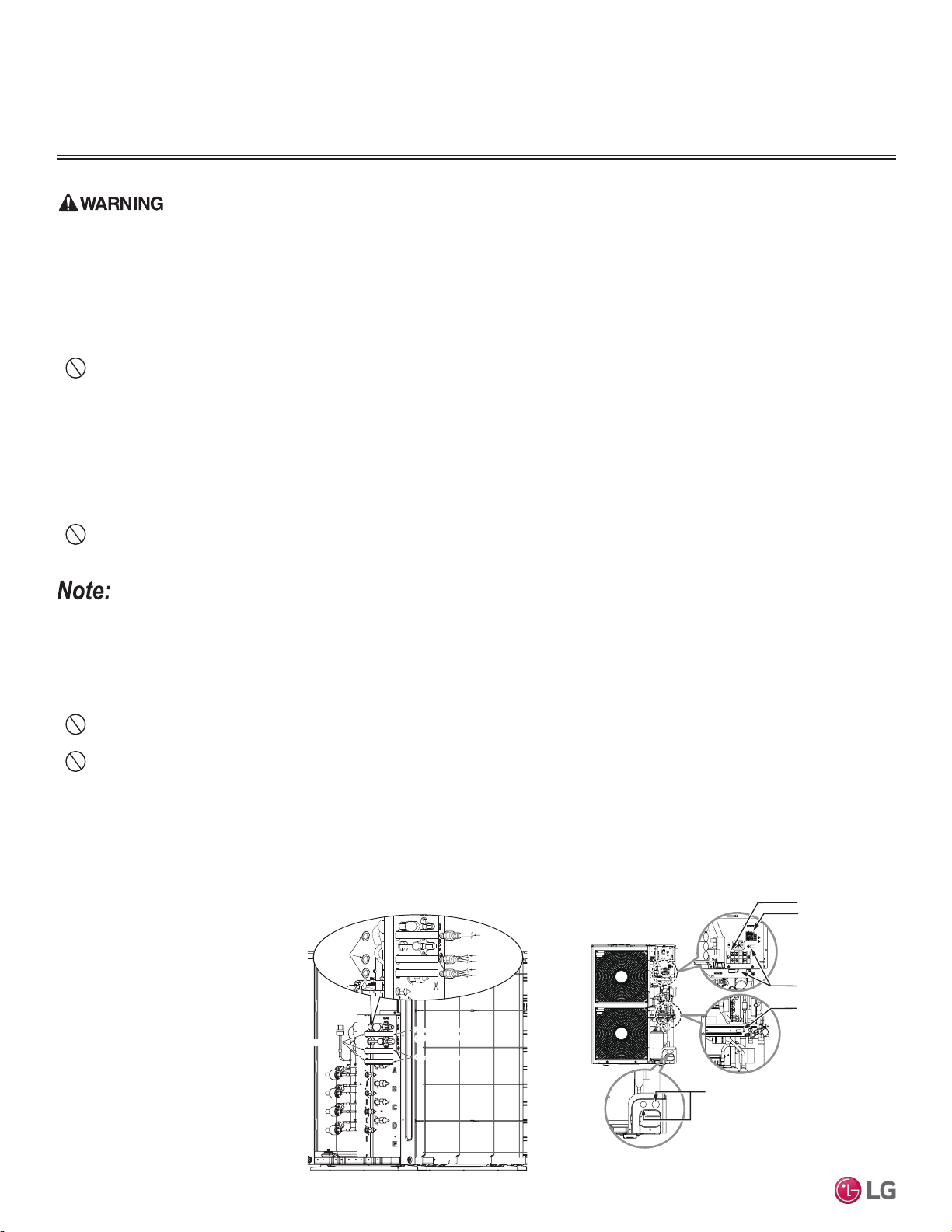
Figure 67: Power Wiring and Communication /
Connection (Power) Cable Paths (LMU18~36CHV;
LMU480, 540HV Example).
1. Detach the outdoor unit panel
by loosening the screws.
2. Remove the control cover (if
applicable) by loosening the
screws.
3. When all connections are
complete, re-attach the
cover control to its original
position using the screws,
then re-attach the outdoor
unit panel.
Power Wiring Terminal
Communication / Connection
(Power) Cable Terminal (To
the Indoor Units / Branch
Distribution Units)
Cable Clamp
Cable Clamp
* Make sure rubber bushings are
properly installed in the knock-out holes
after connecting the main power wiring.
/RFDWLRQ$FFHVVLQJWKH3RZHU:LULQJDQG&RPPXQLFDWLRQV&DEOH
Connections
Figure 68: Location of the Power Wiring and Commu-
nication Cable Terminals LMU600HV).
Power supply cabl
(1Ø, 208/230V)
Power Supply Cable
(1Ø, 208/230V)
Connecting cabl
Connecting Cable
Lock nut
(Field Supplied)
Indoor Unit A
Conduit
(Field Supplied)
Indoor Unit B
Indoor Unit C
Indoor Unit D
Conduit
Hole
Loading ...
Loading ...
Loading ...