Loading ...
Loading ...
Loading ...
SECTION 6- ADJUSTMENTS & REPAIRS
6.13 CUTTING BLADE SERVICE
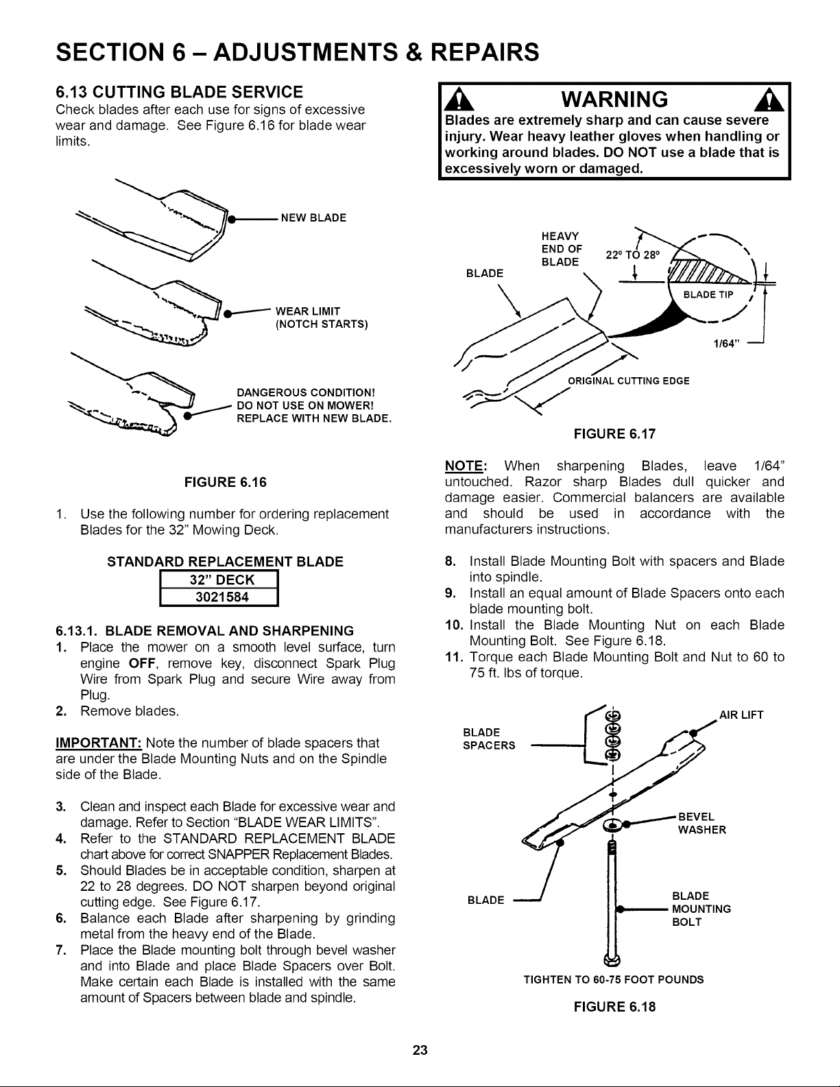
Check blades after each use for signs of excessive
wear and damage. See Figure 6.16 for blade wear
limits.
q_--------- NEW BLADE
WEAR LIMIT
(NOTCH STARTS)
DANGEROUS CONDITION7
DO NOT USE ON MOWER7
REPLACE WITH NEW BLADE.
FIGURE 6.16
1. Use the following number for ordering replacement
Blades for the 32" Mowing Deck.
STANDARD REPLACEMENT BLADE
I I
3021584
6.13.1. BLADE REMOVAL AND SHARPENING
1. Place the mower on a smooth level surface, turn
engine OFF, remove key, disconnect Spark Plug
Wire from Spark Plug and secure Wire away from
Plug.
2. Remove blades.
IMPORTANT: Note the number of blade spacers that
are under the Blade Mounting Nuts and on the Spindle
side of the Blade.
3. Clean and inspect each Blade for excessive wear and
damage. Refer to Section "BLADE WEAR LIMITS".
4. Refer to the STANDARD REPLACEMENT BLADE
chart above for correct SNAPPER Replacement Blades.
5. Should Blades be in acceptable condition, sharpen at
22 to 28 degrees. DO NOT sharpen beyond original
cutting edge. See Figure 6.17.
6. Balance each Blade after sharpening by grinding
metal from the heavy end of the Blade.
7. Place the Blade mounting bolt through bevel washer
and into Blade and place Blade Spacers over Bolt.
Make certain each Blade is installed with the same
amount of Spacers between blade and spindle.
,Ji WARNING
Blades are extremely sharp and can cause severe
injury. Wear heavy leather gloves when handling or
working around blades. DO NOT use a blade that is
excessively worn or damaged.
BLADE
HEAVY
END OF
BLADE
22 ° TO 28 °
\
ORIGINAL CUTTING EDGE
FIGURE 6.17
NOTE: When sharpening Blades, leave 1/64"
untouched. Razor sharp Blades dull quicker and
damage easier. Commercial balancers are available
and should be used in accordance with the
manufacturers instructions.
8. Install Blade Mounting Bolt with spacers and Blade
into spindle.
9. Install an equal amount of Blade Spacers onto each
blade mounting bolt.
10. Install the Blade Mounting Nut on each Blade
Mounting Bolt. See Figure 6.18.
11. Torque each Blade Mounting Bolt and Nut to 60 to
75 ft. Ibs of torque.
_"¢_'__ AIR LIFT
L$
I
÷
BEVEL
R
BLADE '-"-/ BLADE
MOUNTING
BOLT
TIGHTEN TO 60-75 FOOT POUNDS
FIGURE 6.18
23
Loading ...
Loading ...
Loading ...