Loading ...
Loading ...
Loading ...
SECTION 3- OPERATING INSTRUCTIONS
3.2 PRE-START CHECK LIST
Make the following checks and perform the services as
required before each start-up:
1. If required, make cutting height adjustments. Refer
to Section "CUTTING HEIGHT ADJUSTMENT".
2. Check tires and add air as needed to bring
pressure to 25 psi in front and 12-15 psi in rear
tires.
3. Check Guards, Deflector, and Belt Covers to make
sure all are in place and secure.
4. Check Condition of Blade Deck Belt. If damaged,
replace before operating machine. Refer to Section
"DECK BELT ADJUSTMENT & REPLACEMENT".
5. Clean Interior and Exterior Surfaces of cutting deck
and clean Engine of any accumulation of dirt,
grass, oil, etc. Keep Engine air intake screens and
cooling fins clear at all times.
6. Check Engine Oil and add oil as needed to bring
level up to (but not over) the FULL mark. (Refer to
Engine manual for oil specifications).
7. Add Fuel to tank after pushing the Mower outside
where fumes can be dissipated. Make sure Fuel
Tank Cap is tightened after refueling. (Refer to
Engine manual for fuel specifications).
NOTE: DO NOT add fuel while engine is running or hot.
Use fresh, clean, lead-free gasoline. DO NOT use
gasoline that has been stored for long periods. Leaded
gasoline or gasohol is NOT recommended.
3.3 STARTING ENGINE
1. Turn Fuel Shut-Off Valve ON. See Figure 3.9.
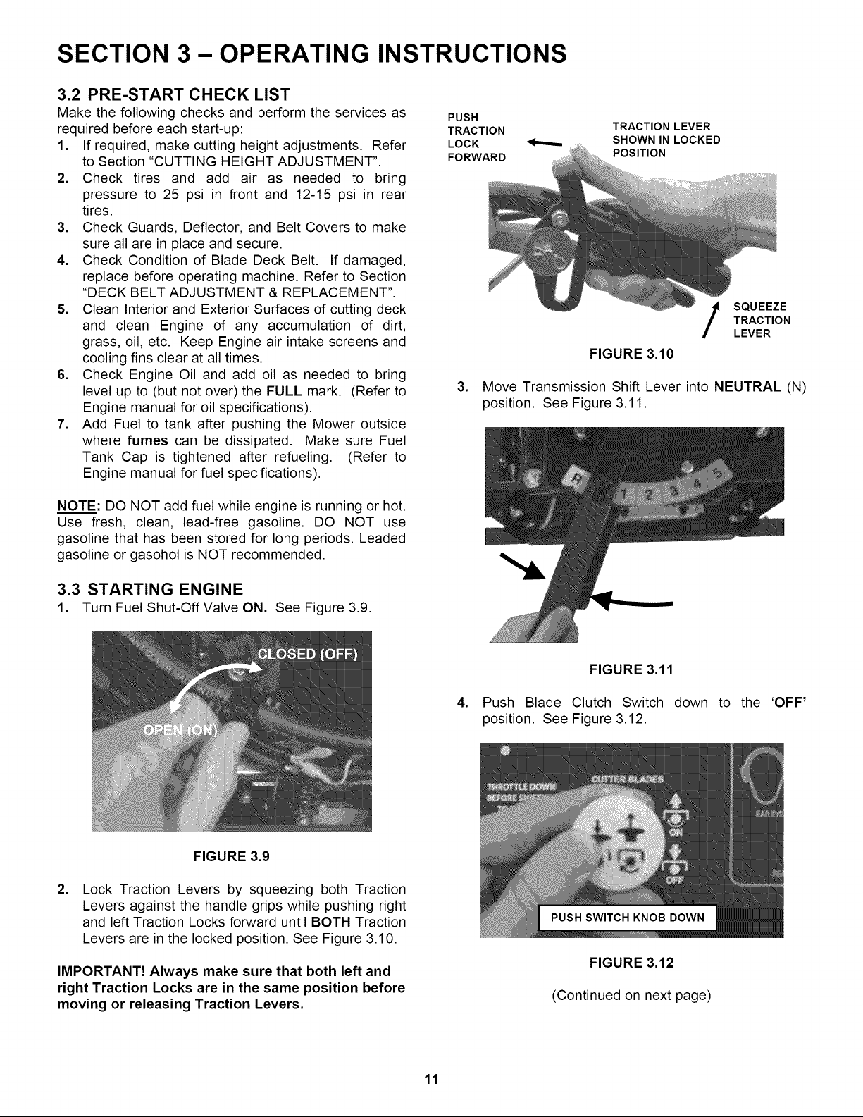
PUSH
TRACTION
LOCK
FORWARD
TRACTION LEVER
SHOWN IN LOCKED
POSITION
.
FIGURE 3.10
SQU EEZE
TRACTION
LEVER
Move Transmission Shift Lever into NEUTRAL (N)
position. See Figure 3.11.
.
FIGURE 3.11
Push Blade Clutch Switch
position. See Figure 3.12.
down to the 'OFF'
FIGURE 3.9
.
Lock Traction Levers by squeezing both Traction
Levers against the handle grips while pushing right
and left Traction Locks forward until BOTH Traction
Levers are in the locked position. See Figure 3.10.
IMPORTANT! Always make sure that both left and
right Traction Locks are in the same position before
moving or releasing Traction Levers.
FIGURE 3.12
(Continued on next page)
11
Loading ...
Loading ...
Loading ...