Loading ...
Loading ...
Loading ...
SECTION 6- ADJUSTMENTS & REPAIRS
6.1 LOWER TRACTION ROD ADJUSTMENT
If mower does not stop firmly when Traction Levers are
squeezed, or if mower veers to one side when Traction
Levers are squeezed, one or both lower traction rods
should be adjusted as follows:
1. Operate mower on level terrain with Transmission
Shift Lever in No. 1 position. Determine which side
requires adjustment.
2. Stop engine, remove the key from switch and
disconnect spark plug wire from spark plug.
Secure wire away from plug.
3. Turn nut on lower traction rod clockwise to increase
tension. See Figure 6.1.
FIGURE 6.1
,
Replace spark plug wire onto spark plug. Start
engine and operate mower with transmission in the
No. 1 position to check for proper adjustment. If
further adjustment is required, follow all steps
above.
6.2 UPPER TRACTION ROD ADJUSTMENT
If one or both Traction Belts do not fully declutch when
traction levers are squeezed against handle grips,
adjust upper traction rods as follows:
1. Move the machine to a smooth, level surface and
turn the engine OFF. Release the traction locks.
See Figure 6.2.
2. Remove the key from the switch, remove the spark
plug wire from the spark plug and secure it away
from the plug.
3. Remove pin and washer from top of rod, and pull
rod end out from traction lock and traction lever.
4. Turn rod clockwise into fitting 1-2 turns. Replace
rod through traction lever and traction lock, and
replace washer and pin.
5. Replace spark plug wire, start machine and check
operation.
6. Repeat steps 1-5 as necessary.
18
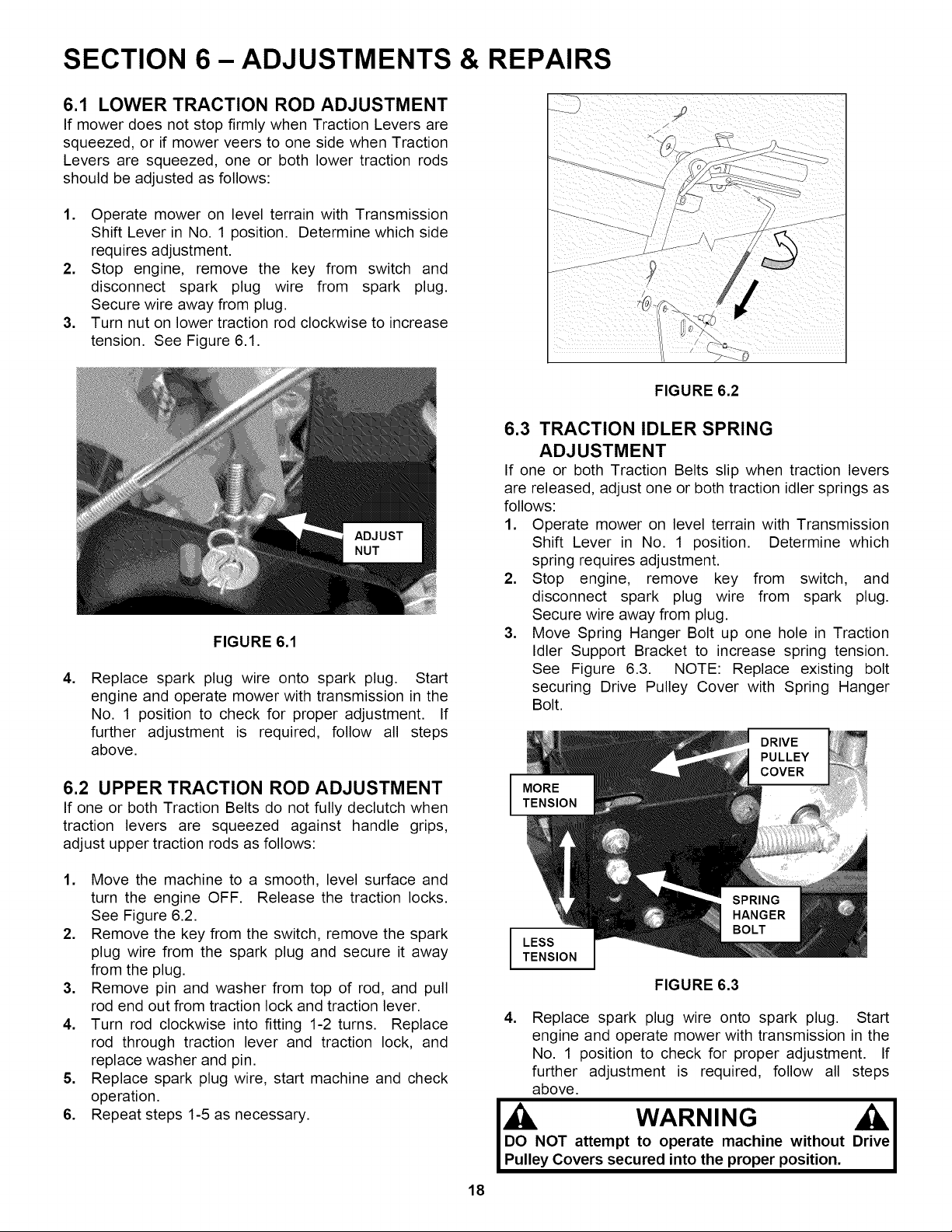
FIGURE 6.2
6.3 TRACTION IDLER SPRING
ADJUSTMENT
If one or both Traction Belts slip when traction levers
are released, adjust one or both traction idler springs as
follows:
1. Operate mower on level terrain with Transmission
Shift Lever in No. 1 position. Determine which
spring requires adjustment.
2. Stop engine, remove key from switch, and
disconnect spark plug wire from spark plug.
Secure wire away from plug.
3. Move Spring Hanger Bolt up one hole in Traction
Idler Support Bracket to increase spring tension.
See Figure 6.3. NOTE: Replace existing bolt
securing Drive Pulley Cover with Spring Hanger
Bolt.
DRIVE
PULLEY
COVER
I
LESS
TENSION
FIGURE 6.3
4. Replace spark plug wire onto spark plug. Start
engine and operate mower with transmission in the
No. 1 position to check for proper adjustment. If
further adjustment is required, follow all steps
above.
j , WARNING Ori_ veI
DO NOT attempt to operate machine without "
Pulley Covers secured into the proper position,
Loading ...
Loading ...
Loading ...