
Safety Instructions and Operator's Manual for
PRO SERIES
WA LK BEHIND
MOWER
SERIES 1
MODEL
SGV13321KW
MODEL NUMBER EXPLANATION
MODEL DESIGNATION
MODEL TYPE
ENGINE HP *
I s IGV1131321 1 I KWI
' I I I '
ENGINE TYPE
SERIES DESIGNATION
DECK SIZE
S - Snapper
GV- Model Desiqnation
I 13-13EnqineHP
32- 32" Cuttinq Deck
I 1 - Series Designation
KW- Kawasaki Enqine
Thank you for buying a SNAPPER Product! Before operating your PRO SERIES WALK BEHIND, read this manual
carefully and pay particular attention to the "IMPORTANT SAFETY INSTRUCTIONS" on Pages 2 - 4. Remember that all
power equipment can be dangerous if used improperly. Also keep in mind that SAFETY requires careful use in
accordance with the operating instructions and common sense!
* Actual sustained equipment horsepower will likely be lower due to operating limitations and environmental factors.
___mmmm
._NAPPER, McDonough,GA., 30253 U.S.A.
COPYRIGHT © 2005
SNAPPER - A Division of Simplicity Manufacturing, Inc.
ALL RIGHTS RESERVED
MANUAL No. 7-8176 (I.R. 1/24/05)

IMPORTANT SAFETY INSTRUCTIONS
WARNING: This powerful cutting machine is capable of amputating hands and feet and can throw objects that
can cause injury and damage! Failure to comply with the following SAFETY instructions could result in serious
injury or death to the operator or other persons. The owner of the machine must understand these instructions
and must allow only persons who understand these instructions to operate machine. Each person operating
the machine must be of sound mind and body and must not be under the influence of any substance, which
might impair vision, dexterity or judgment. If you have any questions pertaining to your machine which your
dealer cannot answer to your satisfaction, call or write the Customer Service Department at SNAPPER,
McDonough, Georgia 30253. Phone: (1-800-935-2967).
PROTECTION FOR CHILDREN
Tragic accidents can occur if the operator is not alert
to the presence of children. Children are often
attracted to the machine and the mowing activity.
Never assume that children will remain where you last
saw them.
1. KEEP children out of the mowing area and under
the watchful care of a responsible adult.
2. DO NOT allow children in yard when machine is
operated (even with the blades OFF).
3. DO NOT allow children or others to ride on
machine, attachments, or towed equipment (even
with the blades OFF). They may fall and be
seriously injured.
4. DO NOT allow pre-teenage children to operate or
service the machine. Local regulations may
restrict the age of the operator.
5. ALLOW only adults or responsible teenagers with
mature judgment under close adult supervision to
operate machine.
6. DO NOT operate blades in reverse. STOP
BLADES. LOOK and SEE behind and down for
children, pets and hazards before and while
backing.
7. USE EXTRA CARE when approaching blind
corners, shrubs, trees, or other objects that may
obscure vision.
SLOPE OPERATION
1. Slopes are a major factor related to slip and fall
accidents, which can result in severe injury. All
slopes require extra caution and slow speed. If
you feel uneasy on a slope, DO NOT mow it.
2. Mow across slopes, never up and down. Exercise
extreme CAUTION when changing directions on
slopes. Practice operation of machine on slopes
with blades off.
3. Use extra care with grass catchers or other
attachments: these affect the handling and the
stability of the machine.
4. DO NOT use tow behind attachments on slopes.
5. AVOID uphill starts.
6. Turf conditions can affect the machine's stability.
DO NOT operate machine under any condition
where traction, steering or stability is doubtful.
7. Chose a low enough ground speed setting so that
you will not have to stop or shift on a slope. Tires
may lose traction on slopes even though the
brakes are functioning properly.
SLOPE OPERATION
(Continued From Previous Column)
8. Always keep the machine in gear when going down
slopes. DO NOT shift to neutral (or actuate the hydro
roll release) and coast down hill.
PREPARATION
1. Read, understand
and follow instructions and
warnings in this manual and on the machine, engine,
and attachments. Know the controls and the proper
use of the machine before starting. If the operators or
mechanics cannot read English, it is the owner's
responsibility to explain this material to them.
2. Only mature, responsible persons shall operate the
machine and only after proper instruction. The owner
is responsible for training the operators. Further, the
owner/operator can prevent and/or is responsible for
accidents or injuries occurring to themselves, other
people or property.
3. Data indicates that operators age 60 and above, are
involved in a large percentage of mower-related
injuries. These operators should evaluate their ability
to operate the mower safely enough to protect
themselves and others from serious injury.
4. Handle fuel with extra care. Fuels are flammable and
vapors are explosive. Use only an approved fuel
container. DO NOT remove fuel cap or add fuel with
engine running. Add fuel outdoors only with engine
stopped and cool. Clean spilled fuel from machine. DO
NOT smoke.
5. Practice operation of machine with BLADES OFF to
learn controls and develop skills.
6. Check the area to be mowed and remove all objects
such as toys, wire, rocks, limbs and other objects that
could cause injury if thrown by blade or interfere with
mowing.
7. Evaluate the terrain to determine what accessories and
attachments are needed to properly and safely perform
the job. Only use accessories and attachments
approved by SNAPPER.
8. Keep people and pets out of mowing area.
Immediately, STOP blades, STOP engine, and Stop
machine if anyone enters the area.
9. DO NOT operate machine unless all shields, deflectors,
switches, blade controls and other safety devices are
in place and functioning properly.
10. Make sure all safety decals are clearly legible. Replace
if damaged.

IMPORTANT SAFETY INSTRUCTIONS
PREPARATION
(Continued From Previous Page)
11. Protect yourself when mowing and wear appropriate
clothing including safety glasses, long pants, ear
protection, hardhat and substantial footwear with
good traction. Long hair, loose clothing or jewelry
may get tangled in moving parts.
12. Know how to STOP blades and engine quickly in
preparation for emergencies.
13. Use extra care when loading or unloading the
machine into a trailer or truck.
14. Check grass catcher components frequently for
signs of wear or deterioration and replace as needed
to prevent injury from thrown objects going through
weak or worn spots.
SAFE HANDLING OF GASOLINE
To avoid personal injury or property damage, use
extreme care in handling gasoline. Gasoline is extremely
flammable and the vapors are explosive
1. Extinguish all cigarettes, cigars, pipes and other
sources of ignition.
2. Use only an approved fuel container.
3. DO NOT remove fuel cap or add fuel with the engine
running. Allow the engine to cool before refueling.
4. DO NOT refuel the machine indoors.
5. DO NOT store the machine or fuel container inside
where there is an open flame, spark or pilot light such
as on a water heater or other appliances.
6. DO NOT fill fuel containers inside a vehicle or on a
truck or trailer bed with a plastic liner. Always place
the containers on the ground away from the vehicle
before filling.
7. Remove gas-powered equipment from the vehicle or
trailer and refuel it on the ground. If this is not
possible, then refuel equipment using a portable
container, rather than a gasoline dispenser nozzle.
8. DO NOT start gas powered equipment in enclosed
vehicles or trailers.
9. Keep the nozzle in contact with the rim of the fuel
tank or container opening at all times until fueling is
complete. DO NOT use a nozzle lock-open device
10. If fuel is spilled on clothing, change clothing
immediately.
11. DO NOT overfill a fuel tank. Replace fuel cap and
tighten securely.
OPERATION
1. DO NOT put hands or feet near or under rotating
parts. Keep clear of the discharge area while the
engine is running.
2. BEFORE STARTING ENGINE, blades must be OFF
and Traction Levers LOCKED in the Traction Lock
position.
OPERATION
(Continued From Previous Column)
3. Stop Blades when crossing gravel drive, walks, and
under any conditions where thrown objects might be
a hazard.
4. DO NOT raise deck with the blades running.
5. Mow only in daylight or good artificial light.
6. USE EXTRA CARE when approaching blind corners,
shrubs, trees or other objects that may obscure
vision.
7. DO NOT operate the machine while under the
influence of alcohol or drugs.
8. After striking a foreign object or if the mower vibrates
abnormally, STOP the blades and engine. Remove the
key. Disconnect and secure the spark plug wire.
Inspect the mower for any damage and repair the
damage.
9. DO NOT operate machine near drop offs, ditches,
embankments, washouts culverts, fences and
protruding objects. STAY ALERT for holes and other
hidden hazards. Tall grass can hide obstacles.
10. DO NOT operate machine on wet grass. Always be
sure of your footing while operating machine,
especially while backing up. Keep a firm grip on the
handle. Walk: never run. Slipping and falling could
cause injury.
11. DO NOT leave the machine with the engine running.
STOP BLADES, STOP ENGINE and REMOVE KEY
before leaving the operator position for any reason.
10. Before cleaning, repairing, or inspecting make
certain blades, engine and all moving parts have
STOPPED. Remove key and secure spark plug wire
away from spark plug key to prevent accidental
starting.
12. STOP MACHINE on level ground, engage parking
brake (if equipped) and make sure engine and blades
have stopped before leaving the operator's position
for any reason including removing grass catcher or
unclogging mower to prevent injury to hands or feet.
13. Blades must be OFF except when cutting grass. Set
blades in highest position when mowing over rough
ground.
14. Keep hands and feet away from rotating blades
underneath deck.
15. DO NOT operate machine without entire grass
catcher or guards in place. DO NOT point discharge
at people, passing cars, windows or doors.
16. Slow down before turning.
17. Watch out for traffic when near or crossing roadways.
18. Move motion control levers SLOWLY to maintain
control during speed and directional changes.
19. DO NOT operate engine in enclosed areas. Engine
exhaust gases contain carbon monoxide, a deadly
poison.

IMPORTANT SAFETY INSTRUCTIONS
MAINTENANCE
1. Shut off fuel while storing or transporting. DO
NOT store machine or fuel container inside where
fumes may reach an open flame, spark or pilot
light such as in a water heater, furnace, clothes
dryer or other gas appliance. Allow engine to cool
before storing machine in an enclosure. Store fuel
container out of the reach of children in a well
ventilated, unoccupied building.
2. Clean grass and debris from engine, mufflers,
drives and cutting units to help prevent fires.
Clean up fuel, oil and excess grease.
3. When draining fuel tank, drain fuel into an
approved container outdoors and away from open
flame.
4. Check brakes frequently (if equipped); adjust,
repair or replace as needed.
5. Keep all bolts, nuts and screws properly tight.
Check that all cotter pins are in proper position.
6. Always provide adequate ventilation when
running engine. Exhaust gases contain carbon
monoxide, an odorless and deadly poison
7. Disconnect battery before performing
maintenance or service. Cranking engine could
cause injury. Disconnect negative (black) cable
from battery first and positive (red) last.
Reconnect positive first and negative last. Charge
battery in an open well ventilated area, free from
spark and flames. Unplug charger before
connecting or disconnecting from battery. Wear
protective clothing and insulated gloves.
8. Park machine on level ground. DO NOT work
under machine without safety blocks.
9. Service engine and clean, adjust or repair only
when engine and blades are stopped. Remove
key. Remove spark plug wire(s) from spark plug(s)
and secure wire(s) away from spark plug(s).
10. DO NOT change engine governor speed settings
or overspeed engine. DO NOT make adjustments
with the engine running.
11. Lubricate machine at intervals specified in manual
to prevent controls from binding.
12. Mower blades are sharp and can cut. Wrap the
blades or wear heavy leather gloves and use
CAUTION when handling them. DO NOT
straighten or weld blades, only replace them.
13. DO NOT test for spark by grounding spark plug
next to spark plug hole; spark plug could ignite
gas exiting engine.
14. Carefully release pressure from components with
stored energy.
15. Have machine serviced by an authorized
SNAPPER dealer at least once a year and have the
dealer install any new safety devices. DO NOT
allow untrained personnel to service the machine.
16. Use only genuine SNAPPER replacement parts to
assure that original standards are maintained.

TABLE OF CONTENTS
IMPORTANT SAFETY INSTRUCTIONS .................................................................................. 2-4
TABLE OF CONTENTS ............................................................................................................... 5
SECTION 1 - FAMILIARIZATION ............................................................................................ 6-7
SECTION 2- DECAL IDENTIFICATION .................................................................................. 7-8
SECTION 3- OPERATING INSTRUCTIONS ........................................................................ 9-14
Before Operating ............................................................................................................ 9
Controls & Their Functions ...................................................................................... 9-10
Pre-Start Checklist ....................................................................................................... 11
Starting Engine ....................................................................................................... 11-12
Machine Movement ................................................................................................. 12-14
Cutting Blade Operation .............................................................................................. 14
Stopping Machine ........................................................................................................ 14
Mowing and Turning on Hillsides .............................................................................. 14
SECTION 4 - TROUBLESHOOTING ................................................................................... 15-16
Engine Troubleshooting .............................................................................................. 15
Mower Troubleshooting ......................................................................................... 15-16
Transmission Troubleshooting .................................................................................. 16
SECTION 5 - MAINTENANCE .................................................................................................. 17
General Maintenance Schedule .................................................................................. 17
Safety Interlock System Checks ................................................................................. 17
SECTION 6 - ADJUSTMENTS & REPAIRS ........................................................................ 18-23
Lower Traction Rod Adjustment ................................................................................ 18
Upper Traction Rod Adjustment ................................................................................ 18
Traction Idler Spring Adjustment ............................................................................... 18
Handle Height Adjustment .......................................................................................... 19
Transmission Shift Indicator Adjustment ................................................................. 19
Cutting Height Adjustment .................................................................................... 19-20
Deck Belt Adjustment & Replacement ....................................................................... 20
Transmission Belt Adjustment & Replacement ........................................................ 21
Traction Belt Replacement .................................................................................... 21-22
Replacement Parts ....................................................................................................... 22
Transmission Parts & Service .................................................................................... 22
Cutting Blade Service: Removal, Sharpening, Balancing & Replacement ............ 23
SECTION 7 - ELECTRICAL ...................................................................................................... 24
WARRANTY AND PRODUCT REGISTRATION .................................................................. 25-26
PRIMARY MAINTENANCE ................................................................................................... 27-30

SECTION 1 - FAMILIARIZATION
IMPORTANT
The figures and illustrations in this manual
are provided for reference only and may differ
from your specific model. Contact your
Snapper dealer if you have questions.
FUEL TANK
STARTER ROPE
AIR FILTER
DISCHARGE
DEFLECTOR
DECK COVER
DECK HEIGHT
ADJUSTMENT
SPACERS
FRONT CASTER
ASSEMBLY (2)
FUEL
CAP .....
CUTTING DECK
DASHBOARD
SEEFIGURE1.2
........COVER
RETAINING
STRAP (2)
OPERATOR'S
PRESENCE
CONTROL(OPC)
(L&R)
%
TRACTION
LOCK
(L&R)
TRACTION
LEVER
(L&R)
TRANSMISSION SHIFT
LEVER
REAR TIRE
FIGURE
1.1 INTRODUCTION
This manual has been prepared for the operator's of the
SNAPPER PRO SERIES WALK BEHIND MOWER. Its
purpose, aside from recommending standard operating
procedures and routine service requirements, is to
promote SAFETY through the use of accepted operating
practices. Read, Understand and Follow the IMPORTANT
SAFETY INSTRUCTIONS on Pages 2 thru 4 of this
manual and All SAFETY messages on the PRO SERIES
WALK BEHIND MOWER and its attachments before
operating. SNAPPER recommends returning the
MACHINE to an authorized SNAPPER dealer annually for
inspection and addition of any new devices which might
upgrade the safety of the mower.
1.1
1.2 NOMENCLATURE
It is recommended that all operator's of this equipment
become thoroughly familiar with the controls,
components, and operation of this machine before
operating. Specific details involving the engine are
found in the separate engine owner's manual. Study
these manuals before operating and keep both handy for
future reference. For the nearest SNAPPER dealer in
your area, check the yellow pages under the heading
LAWN MOWERS. For engine parts and service, look for
the engine manufacturer's dealers under the heading,
ENGINES - gasoline.

SECTION 1 - FAMILIARIZATION
ENGINE SPEED
CONTROL/ BLADE CLUTCH
LEFT HAND CHOKE CONTROL SWITCH
TRACTION LOCK
LEFT HAND
OPERATOR'S
PRESENCE
{OPc)CON TRO L
KEY SWITCH
RIGHT HAND
TRACTION LOCK
RIGHT HAND
OPERATOR'S
PRESENCE
..... CONTROL
(OPC)
LEFT
HANDLE
GRIP
RIGHT
HANDLE
GRIP
LEFT HAND
TRACTION LEVER
RIGHT HAND
TRACTION LEVER
REVERSE
LOCKOUT TRANSMISSION
LEVER SHIFT LEVER
CONTROL LOCATIONS
FIGURE 1.2
SECTION 2- DECAL IDENTIFICATION
DASHBOARD OVERLAY

SECTION 2- DECAL IDENTIFICATION
HEARING PROTECTION
CAUTION! OPEN BELT DRIVE
TRANSMISSION SHIFT INDICATOR
DANGER! ROTATING BLADES
IMPORTANT SAFETY AND OPERATING INSTRUCTIONS
SECTION 3- OPERATING INSTRUCTIONS
WARNING
DO NOT allow operation of the machine by
untrained personnel.
IMPORTANT! BEFORE OPERATING:
Be thoroughly familiar with all controls and how to use
them before operating the machine. Know beforehand
how to STOP machine motion, mower blades and
engine in preparation for possible emergencies.
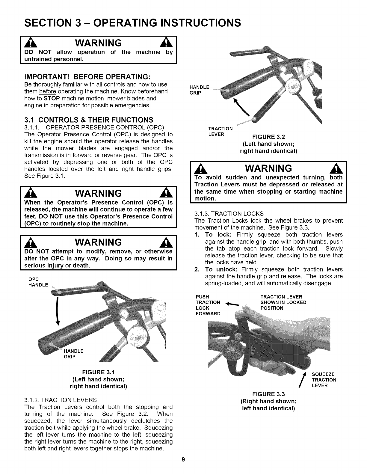
3.1 CONTROLS & THEIR FUNCTIONS
3.1.1. OPERATOR PRESENCE CONTROL (OPC)
The Operator Presence Control (OPC)is designed to
kill the engine should the operator release the handles
while the mower blades are engaged and/or the
transmission is in forward or reverse gear. The OPC is
activated by depressing one or both of the OPC
handles located over the left and right handle grips.
See Figure 3.1.
WARNING
When the Operator's Presence Control (OPC) is
released, the machine will continue to operate a few
feet. DO NOT use this Operator's Presence Control
(OPC) to routinely stop the machine.
WARNING
DO NOT attempt to modify, remove, or otherwise
alterthe OPC in any way. Doing so may resultin
serious injuryor death.
OPC
HANDLE
HANDLE
GRIP
TRACTION
LEVER
FIGURE 3.2
(Left hand shown;
right hand identical)
WARNING
To avoid sudden and unexpected turning, both
TractionLevers must be depressed or releasedat
the same time when stopping or startingmachine
motion.
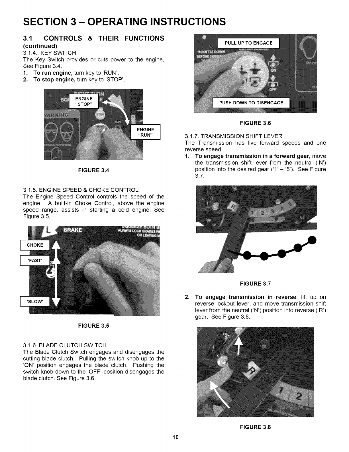
3.1.3. TRACTION LOCKS
The Traction Locks lock the wheel brakes to prevent
movement of the machine. See Figure 3.3.
1. To lock: Firmly squeeze both traction levers
against the handle grip, and with both thumbs, push
the tab atop each traction lock forward. Slowly
release the traction lever, checking to be sure that
the locks have held.
2. To unlock: Firmly squeeze both traction levers
against the handle grip and release. The locks are
spring-loaded, and will automatically disengage.
PUSH TRACTION LEVER
TRACTION _ SHOWN IN LOCKED
LOCK POSITION
FORWARD
HANDLE
GRIP
FIGURE 3.1
(Left hand shown;
right hand identical)
3.1.2. TRACTION LEVERS
The Traction Levers control both the stopping and
turning of the machine. See Figure 3.2. When
squeezed, the lever simultaneously declutches the
traction belt while applying the wheel brake. Squeezing
the left lever turns the machine to the left, squeezing
the right lever turns the machine to the right, squeezing
both left and right levers together stops the machine.
9
FIGURE 3.3
(Right hand shown;
left hand identical)
SQU EEZE
TRACTION
LEVER
SECTION 3- OPERATING INSTRUCTIONS
3.1 CONTROLS & THEIR FUNCTIONS
(continued)
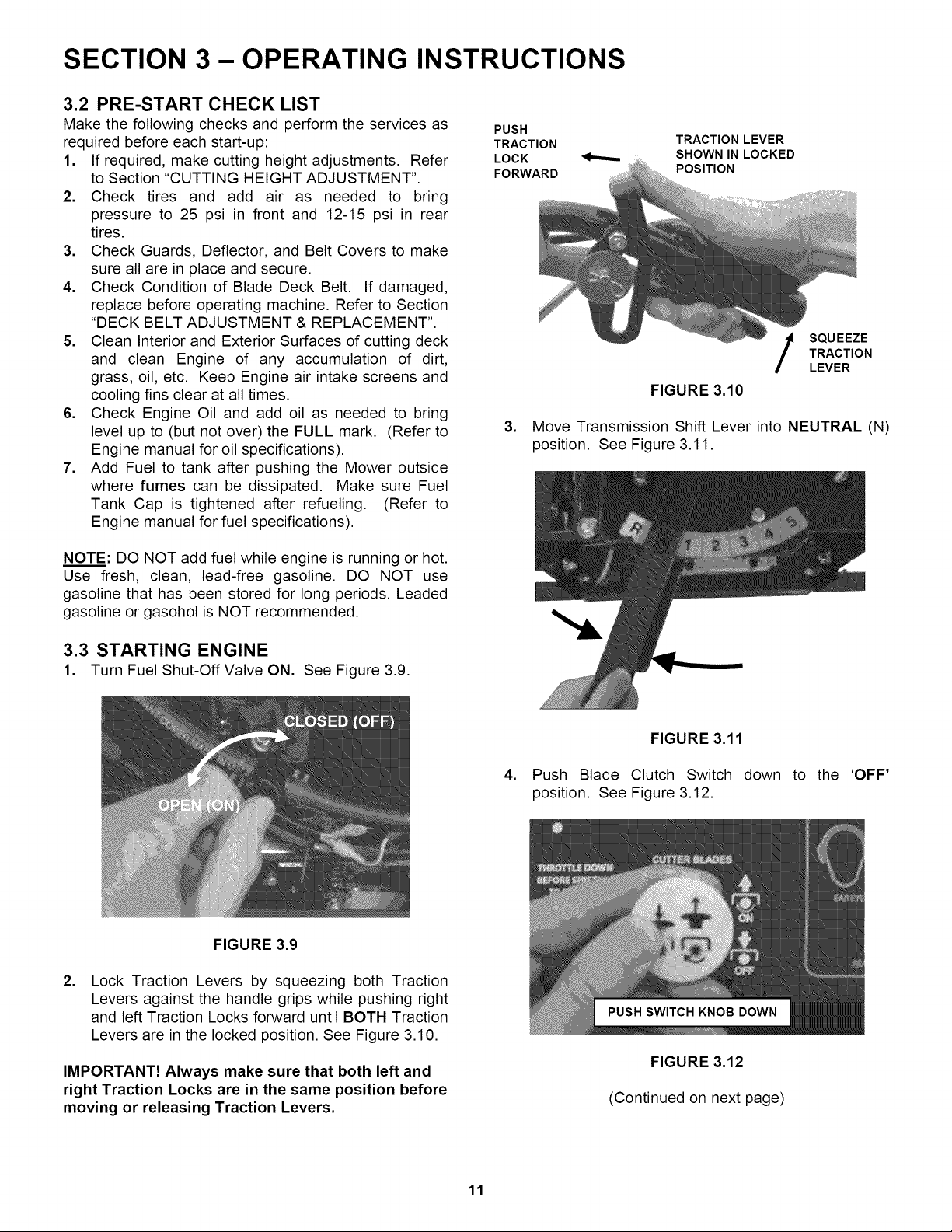
3.1.4. KEY SWITCH
The Key Switch provides or cuts power to the engine.
See Figure 3.4.
1. To run engine, turn key to 'RUN'.
2. To stop engine, turn key to 'STOP'.
FIGURE 3.4
3.1.5. ENGINE SPEED & CHOKE CONTROL
The Engine Speed Control controls the speed of the
engine. A built-in Choke Control, above the engine
speed range, assists in starting a cold engine. See
Figure 3.5.
FIGURE 3.6
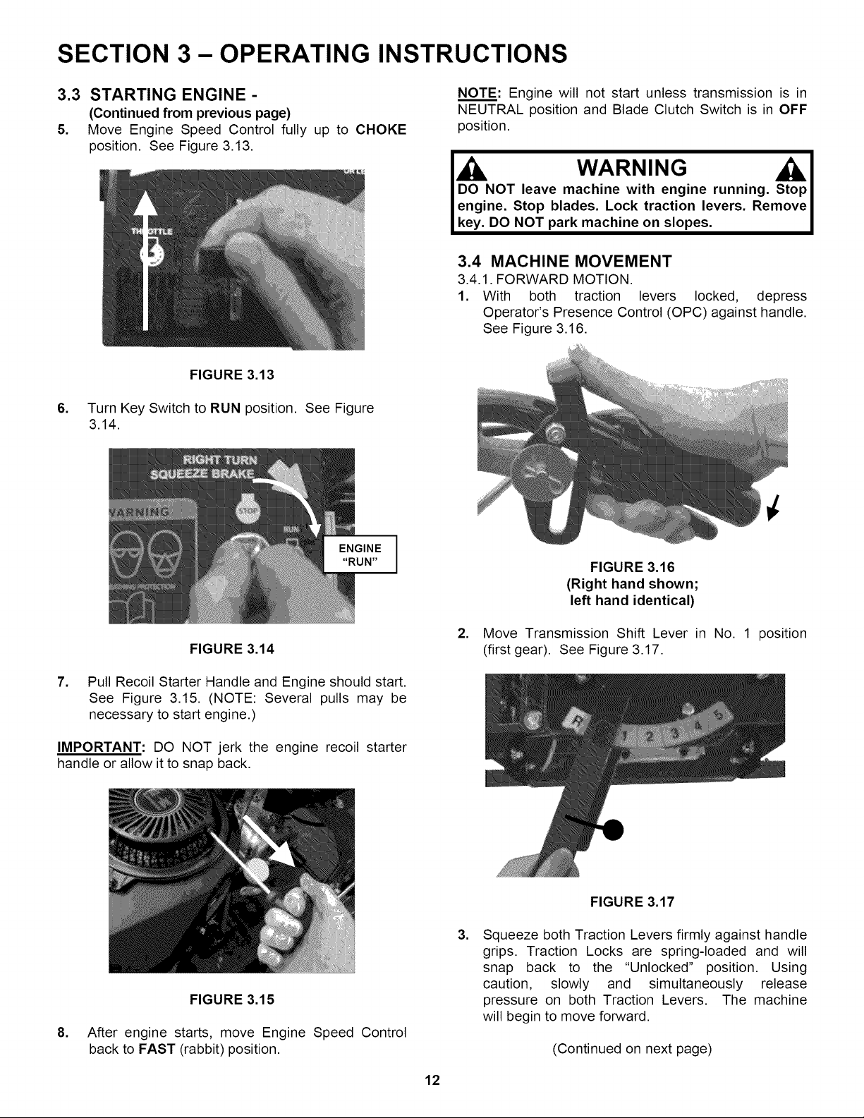
3.1.7. TRANSMISSION SHIFT LEVER
The Transmission has five forward speeds and one
reverse speed.
1. To engage transmission in a forward gear, move
the transmission shift lever from the neutral ('N')
position into the desired gear ('1' - '5'). See Figure
3.7.
FIGURE 3.5
,
FIGURE 3.7
To engage transmission in reverse, lift up on
reverse lockout lever, and move transmission shift
lever from the neutral ('N') position into reverse ('R')
gear. See Figure 3.8.
3.1.6. BLADE CLUTCH SWITCH
The Blade Clutch Switch engages and disengages the
cutting blade clutch. Pulling the switch knob up to the
'ON' position engages the blade clutch. Pushing the
switch knob down to the 'OFF' position disengages the
blade clutch. See Figure 3.6.
10
FIGURE 3.8
SECTION 3- OPERATING INSTRUCTIONS
3.2 PRE-START CHECK LIST
Make the following checks and perform the services as
required before each start-up:
1. If required, make cutting height adjustments. Refer
to Section "CUTTING HEIGHT ADJUSTMENT".
2. Check tires and add air as needed to bring
pressure to 25 psi in front and 12-15 psi in rear
tires.
3. Check Guards, Deflector, and Belt Covers to make
sure all are in place and secure.
4. Check Condition of Blade Deck Belt. If damaged,
replace before operating machine. Refer to Section
"DECK BELT ADJUSTMENT & REPLACEMENT".
5. Clean Interior and Exterior Surfaces of cutting deck
and clean Engine of any accumulation of dirt,
grass, oil, etc. Keep Engine air intake screens and
cooling fins clear at all times.
6. Check Engine Oil and add oil as needed to bring
level up to (but not over) the FULL mark. (Refer to
Engine manual for oil specifications).
7. Add Fuel to tank after pushing the Mower outside
where fumes can be dissipated. Make sure Fuel
Tank Cap is tightened after refueling. (Refer to
Engine manual for fuel specifications).
NOTE: DO NOT add fuel while engine is running or hot.
Use fresh, clean, lead-free gasoline. DO NOT use
gasoline that has been stored for long periods. Leaded
gasoline or gasohol is NOT recommended.
3.3 STARTING ENGINE
1. Turn Fuel Shut-Off Valve ON. See Figure 3.9.
PUSH
TRACTION
LOCK
FORWARD
TRACTION LEVER
SHOWN IN LOCKED
POSITION
.
FIGURE 3.10
SQU EEZE
TRACTION
LEVER
Move Transmission Shift Lever into NEUTRAL (N)
position. See Figure 3.11.
.
FIGURE 3.11
Push Blade Clutch Switch
position. See Figure 3.12.
down to the 'OFF'
FIGURE 3.9
.
Lock Traction Levers by squeezing both Traction
Levers against the handle grips while pushing right
and left Traction Locks forward until BOTH Traction
Levers are in the locked position. See Figure 3.10.
IMPORTANT! Always make sure that both left and
right Traction Locks are in the same position before
moving or releasing Traction Levers.
FIGURE 3.12
(Continued on next page)
11
SECTION 3- OPERATING INSTRUCTIONS
3.3 STARTING ENGINE -
(Continued from previous page)
5. Move Engine Speed Control fully up to CHOKE
position. See Figure 3.13.
NOTE: Engine will not start unless transmission is in
NEUTRAL position and Blade Clutch Switch is in OFF
position.
WARNING ILI
DO NOT leave machine with engine running. Stop I
engine. Stop blades. Lock traction levers. Remove I
key. DO NOT park machine on slopes. I
3.4 MACHINE MOVEMENT
3.4.1. FORWARD MOTION.
1. With both traction levers locked, depress
Operator's Presence Control (OPC) against handle.
See Figure 3.16.
.
FIGURE 3.13
Turn Key Switch to RUN position. See Figure
3.14.
FIGURE 3.14
7. Pull Recoil Starter Handle and Engine should start.
See Figure 3.15. (NOTE: Several pulls may be
necessary to start engine.)
IMPORTANT: DO NOT jerk the engine recoil starter
handle or allow it to snap back.
.
FIGURE 3.16
(Right hand shown;
left hand identical)
Move Transmission Shift Lever in No. 1 position
(first gear). See Figure 3.17.
.
FIGURE 3.15
After engine starts, move Engine Speed Control
back to FAST (rabbit) position.
12
FIGURE 3.17
.
Squeeze both Traction Levers firmly against handle
grips. Traction Locks are spring-loaded and will
snap back to the "Unlocked" position. Using
caution, slowly and simultaneously release
pressure on both Traction Levers. The machine
will begin to move forward.
(Continued on next page)
SECTION 3- OPERATING INSTRUCTIONS
3.4 MACHINE MOVEMENT -
(Continued from previous page)
NOTE: Releasing the Operator's Presence Control
(OPC) while Transmission is in GEAR and/or Blades
are ON will ground the Ignition Circuit and cause the
Engine to STOP, allowing the Machine to travel only a
few feet before coming to a complete STOP.
During initial training time with machine, it is
advised that the operator(s) practice all mower
movements while operating the mower with the
transmission shift lever in no. 1 (first gear) travel
speed position and blade clutch switch in off
position! DO NOT make sharp turns at high speeds!
IMPORTANT: Always STOP machine movement and
lock traction levers before changing to a different
ground speed. Transmission damage could result if
ground speed is changed when machine is moving.
3.4.2. TURNING AND BRAKING.
:)IL WARNING
Machine should always be in forward motion before
attempting a turn. DO NOT attempt a turn from a
stopped position.
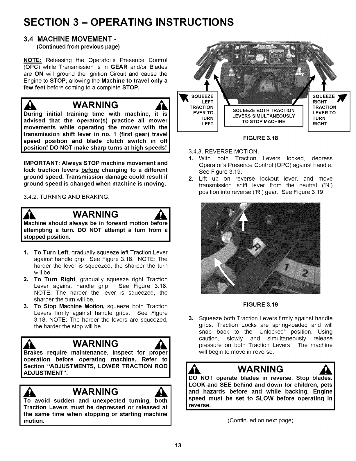
1. To Turn Left, gradually squeeze left Traction Lever
against handle grip. See Figure 3.18. NOTE: The
harder the lever is squeezed, the sharper the turn
will be.
2. To Turn Right, gradually squeeze right Traction
Lever against handle grip. See Figure 3.18.
NOTE: The harder the lever is squeezed, the
sharper the turn will be.
3. To Stop Machine Motion, squeeze both Traction
Levers firmly against handle grips. See Figure
3.18. NOTE: The harder the levers are squeezed,
the harder the stop will be.
Brakes require maintenance. Inspect for proper
operation before operating machine. Refer to
Section "ADJUSTMENTS, LOWER TRACTION ROD
ADJUSTMENT".
WARNING
To avoid sudden and unexpected turning, both
Traction Levers must be depressed or released at
the same time when stopping or starting machine
motion.
_ SQUEEZE SQUEEZE _'
LEFT RIGHT
TRACTION TRACTION
LEVER TO SQUEEZE BOTH TRACTION LEVER TO
TURN LEVERS SIMULTANEOUSLY TURN
LEFT TO STOP MACHINE RIGHT
FIGURE 3.18
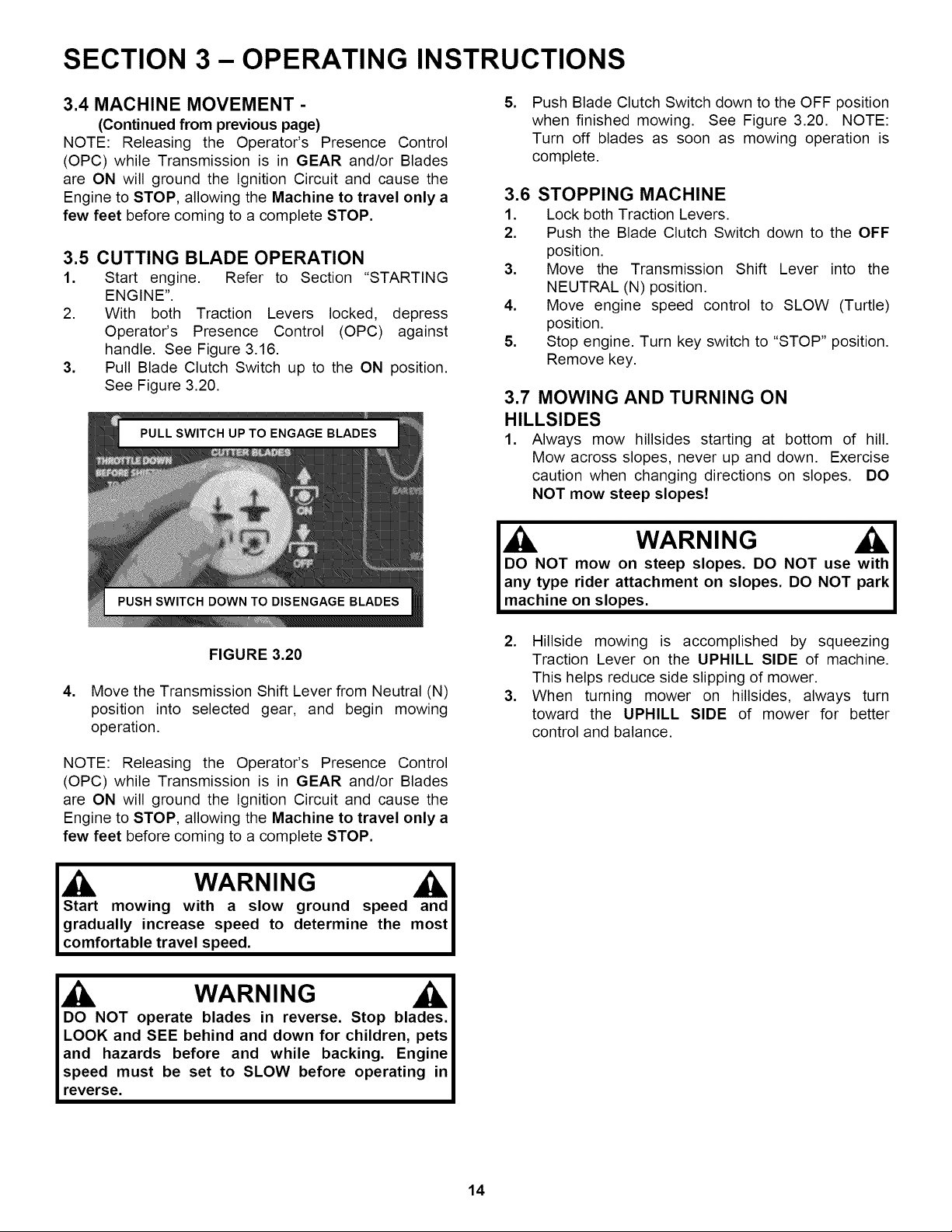
3.4.3. REVERSE MOTION.
1. With both Traction Levers locked, depress
Operator's Presence Control (OPC) against handle.
See Figure 3.19.
2. Lift up on reverse lockout lever, and move
transmission shift lever from the neutral ('N')
position into reverse ('R') gear. See Figure 3.19.
FIGURE 3.19
.
Squeeze both Traction Levers firmly against handle
grips. Traction Locks are spring-loaded and will
snap back to the "Unlocked" position. Using
caution, slowly and simultaneously release
pressure on both Traction Levers. The machine
will begin to move in reverse.
I DO NOT operate blades in reverse. Stop blades. I
LOOK and SEE behind and down for children, pets I
and hazards before and while backing. Engine I
speed must be set to SLOW before operating inI
reverse. I
(Continued on next page)
13
SECTION 3- OPERATING INSTRUCTIONS
3.4 MACHINE MOVEMENT -
(Continued from previous page)
NOTE: Releasing the Operator's Presence Control
(OPC) while Transmission is in GEAR and/or Blades
are ON will ground the Ignition Circuit and cause the
Engine to STOP, allowing the Machine to travel only a
few feet before coming to a complete STOP.
3.5 CUTTING BLADE OPERATION
1. Start engine. Refer to Section "STARTING
ENGINE".
2. With both Traction Levers locked, depress
Operator's Presence Control (OPC) against
handle. See Figure 3.16.
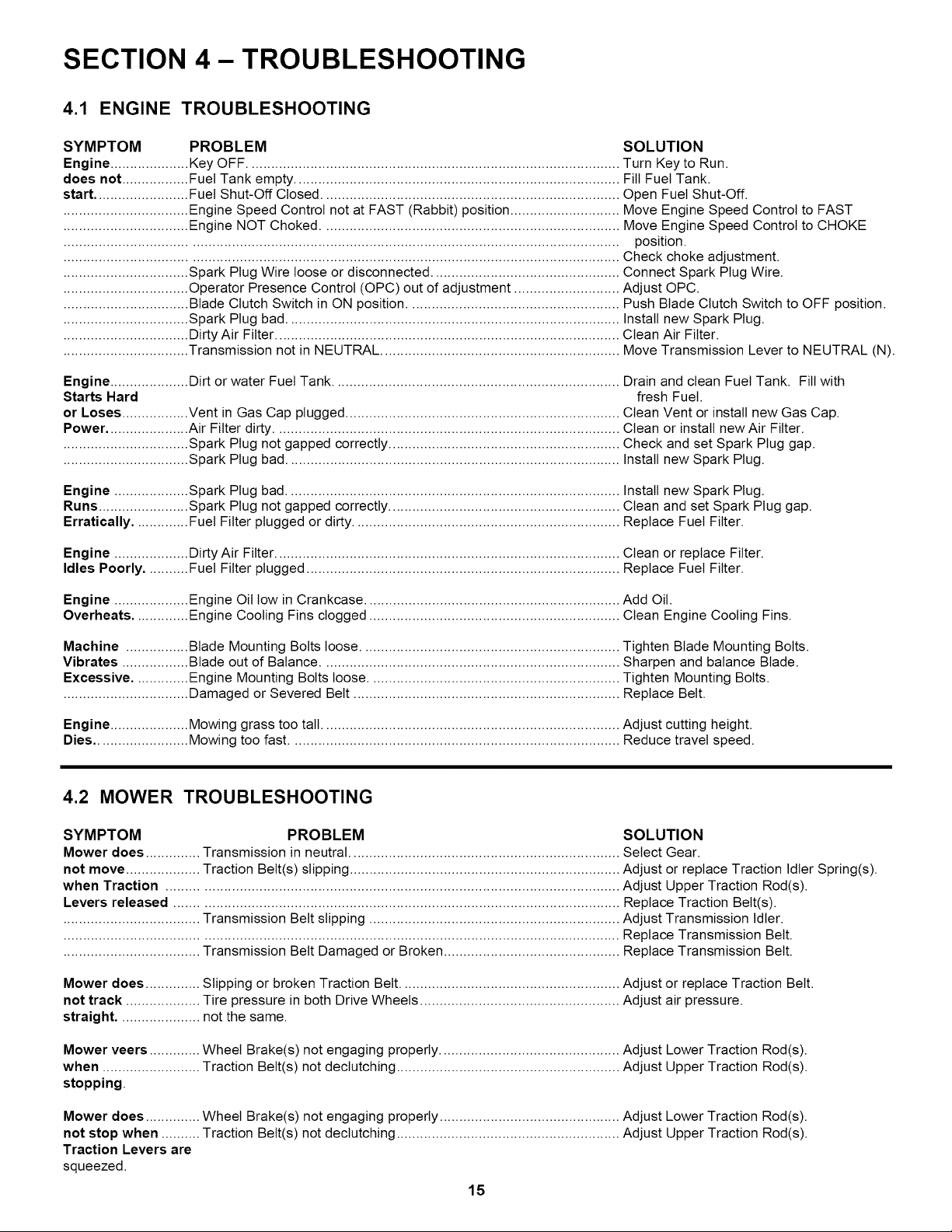
3. Pull Blade Clutch Switch up to the ON position.
See Figure 3.20.
FIGURE 3.20
4. Move the Transmission Shift Lever from Neutral (N)
position into selected gear, and begin mowing
operation.
NOTE: Releasing the Operator's Presence Control
(OPC) while Transmission is in GEAR and/or Blades
are ON will ground the Ignition Circuit and cause the
Engine to STOP, allowing the Machine to travel only a
few feet before coming to a complete STOP.
.
Push Blade Clutch Switch down to the OFF position
when finished mowing. See Figure 3.20. NOTE:
Turn off blades as soon as mowing operation is
complete.
3.6 STOPPING MACHINE
1. Lock both Traction Levers.
2. Push the Blade Clutch Switch down to the OFF
position.
3. Move the Transmission Shift Lever into the
NEUTRAL (N) position.
4. Move engine speed control to SLOW (Turtle)
position.
5. Stop engine. Turn key switch to "STOP" position.
Remove key.
3.7 MOWING AND TURNING ON
HILLSIDES
1. Always mow hillsides starting at bottom of hill.
Mow across slopes, never up and down. Exercise
caution when changing directions on slopes. DO
NOT mow steep slopes!
DO NOT mow on steep slopes. DO NOT use "
any type rider attachment on slopes. DO NOT
machine on slopes.
2. Hillside mowing is accomplished by squeezing
Traction Lever on the UPHILL SIDE of machine.
This helps reduce side slipping of mower.
3. When turning mower on hillsides, always turn
toward the UPHILL SIDE of mower for better
control and balance.
WARNING
Start mowing with a slow ground speed and
gradually increase speed to determine the most
comfortabletravelspeed.
DO NOT operate blades in reverse. Stop blades.
LOOK and SEE behind and down for children, pets
and hazards before and while backing. Engine
speed must be set to SLOW before operating in
reverse.
14
SECTION 4- TROUBLESHOOTING
4.1 ENGINE TROUBLESHOOTING
SYMPTOM PROBLEM SOLUTION
Engine .................... Key OFF ............................................................................................... Turn Key to Run.
does not ................. Fuel Tank empty ................................................................................... Fill Fuel Tank.
start ........................ Fuel Shut-Off Closed ............................................................................ Open Fuel Shut-Off.
................................ Engine Speed Control not at FAST (Rabbit) position ............................ Move Engine Speed Control to FAST
................................ Engine NOT Choked ............................................................................ Move Engine Speed Control to CHOKE
............................................................................................................................................. position.
............................................................................................................................................. Check choke adjustment.
................................ Spark Plug Wire loose or disconnected ................................................ Connect Spark Plug Wire.
................................ Operator Presence Control (OPC) out of adjustment ........................... Adjust OPC.
................................ Blade Clutch Switch in ON position ...................................................... Push Blade Clutch Switch to OFF position.
................................ Spark Plug bad ..................................................................................... Install new Spark Plug.
................................ Dirty Air Filter ........................................................................................ Clean Air Filter.
................................ Transmission not in NEUTRAL ............................................................. Move Transmission Lever to NEUTRAL (N).
Engine .................... Dirt or water Fuel Tank ......................................................................... Drain and clean Fuel Tank. Fill with
Starts Hard fresh Fuel.
or Loses ................. Vent in Gas Cap plugged ...................................................................... Clean Vent or install new Gas Cap.
Power ..................... Air Filter dirty ........................................................................................ Clean or install new Air Filter.
................................ Spark Plug not gapped correctly ........................................................... Check and set Spark Plug gap.
................................ Spark Plug bad ..................................................................................... Install new Spark Plug.
Engine ................... Spark Plug bad ..................................................................................... Install new Spark Plug.
Runs ....................... Spark Plug not gapped correctly ........................................................... Clean and set Spark Plug gap.
Erratically .............. Fuel Filter plugged or dirty .................................................................... Replace Fuel Filter.
Engine ................... Dirty Air Filter ........................................................................................ Clean or replace Filter.
Idles Poorly ........... Fuel Filter plugged ................................................................................ Replace Fuel Filter.
Engine ................... Engine Oil tow in Crankcase ................................................................. Add Oil.
Overheats .............. Engine Cooling Fins clogged ................................................................ Clean Engine Cooling Fins.
Machine ................ Blade Mounting Bolts loose .................................................................. Tighten Blade Mounting Bolts.
Vibrates ................. Blade out of Balance ............................................................................ Sharpen and balance Blade.
Excessive .............. Engine Mounting Bolts loose ................................................................ Tighten Mounting Bolts.
................................ Damaged or Severed Belt .................................................................... Replace Belt.
Engine .................... Mowing grass too tall ............................................................................ Adjust cutting height.
Dies ........................ Mowing too fast .................................................................................... Reduce travel speed.
4.2 MOWER TROUBLESHOOTING
SYMPTOM PROBLEM SOLUTION
Mower does .............. Transmission in neutral ..................................................................... Select Gear.
not move ................... Traction Belt(s) slipping ..................................................................... Adjust or replace Traction Idler Spring(s).
when Traction ................................................................................................................... Adjust Upper Traction Rod(s).
Levers released ................................................................................................................. Replace Traction Belt(s).
................................... Transmission Belt slipping ................................................................ Adjust Transmission Idler.
............................................................................................................................................. Replace Transmission Belt.
................................... Transmission Belt Damaged or Broken ............................................. Replace Transmission Belt.
Mower does .............. Slipping or broken Traction Belt ........................................................ Adjust or replace Traction Belt.
not track ................... Tire pressure in both Drive Wheels ................................................... Adjust air pressure.
straight ..................... not the same.
Mower veers ............. Wheel Brake(s) not engaging properly .............................................. Adjust Lower Traction Rod(s).
when ......................... Traction Belt(s) not declutching ......................................................... Adjust Upper Traction Rod(s).
stopping.
Mower does .............. Wheel Brake(s) not engaging properly .............................................. Adjust Lower Traction Rod(s).
not stop when .......... Traction Belt(s) not declutching ......................................................... Adjust Upper Traction Rod(s).
Traction Levers are
squeezed.
15
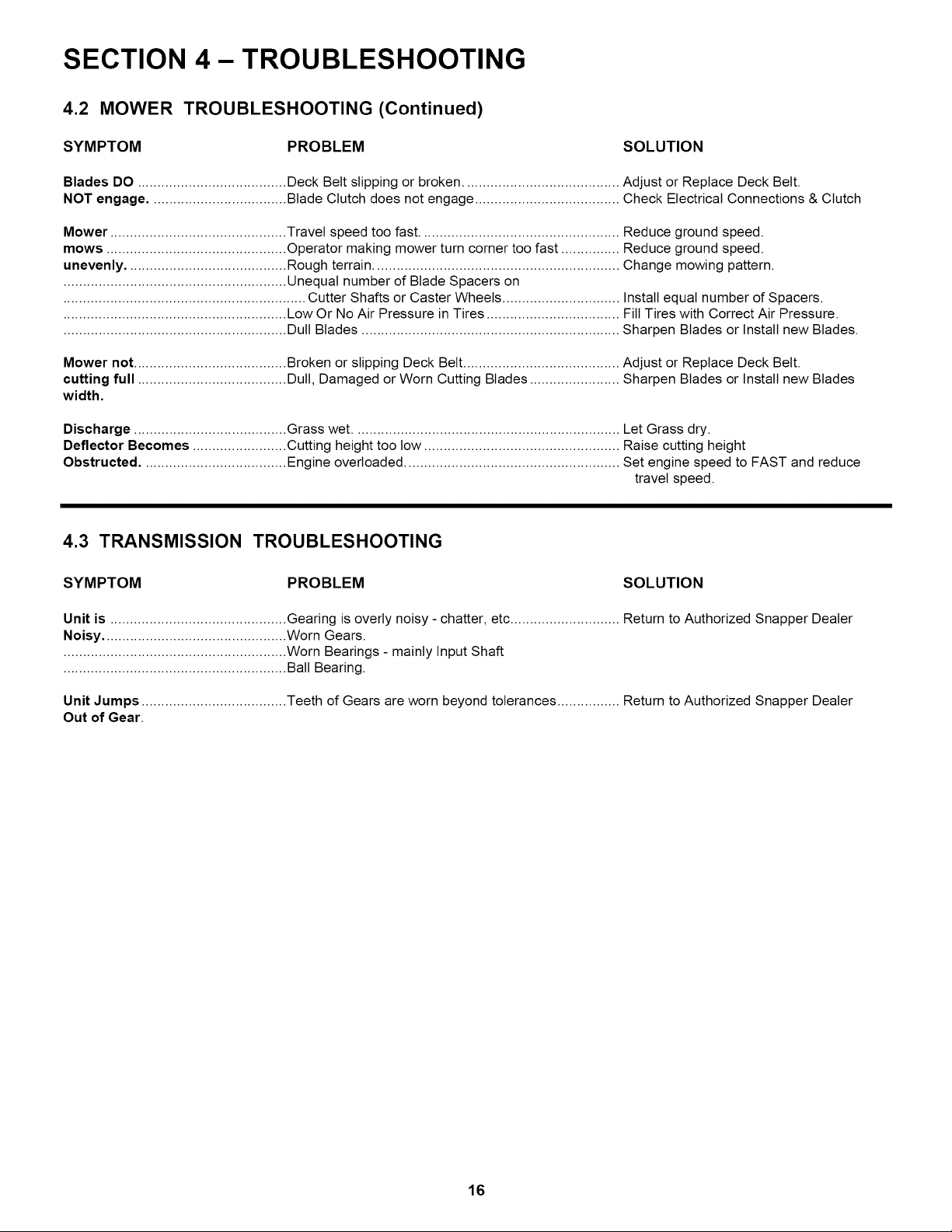
SECTION 4- TROUBLESHOOTING
4.2 MOWER TROUBLESHOOTING (Continued)
SYMPTOM PROBLEM SOLUTION
Blades DO ...................................... Deck Belt slipping or broken ........................................ Adjust or Replace Deck Belt.
NOT engage ................................... Blade Clutch does not engage ..................................... Check Electrical Connections & Clutch
Mower ............................................. Travel speed too fast ................................................... Reduce ground speed.
mows .............................................. Operator making mower turn corner too fast ............... Reduce ground speed.
unevenly ......................................... Rough terrain ............................................................... Change mowing pattern.
......................................................... Unequal number of Blade Spacers on
.............................................................. Cutter Shafts or Caster Wheels .............................. Install equal number of Spacers.
......................................................... Low Or No Air Pressure in Tires .................................. Fill Tires with Correct Air Pressure.
......................................................... Dull Blades .................................................................. Sharpen Blades or Install new Blades.
Mower not ....................................... Broken or slipping Deck Belt ........................................ Adjust or Replace Deck Belt.
cutting full ...................................... Dull, Damaged or Worn Cutting Blades ....................... Sharpen Blades or Install new Blades
width.
Discharge ....................................... Grass wet .................................................................... Let Grass dry.
Deflector Becomes ........................ Cutting height too tow .................................................. Raise cutting height
Obstructed ..................................... Engine overloaded ....................................................... Set engine speed to FAST and reduce
travel speed.
4.3 TRANSMISSION TROUBLESHOOTING
SYMPTOM PROBLEM SOLUTION
Unit is ............................................. Gearing is overly noisy - chatter, etc ............................ Return to Authorized Snapper Dealer
Noisy ............................................... Worn Gears.
......................................................... Worn Bearings - mainly Input Shaft
......................................................... Ball Bearing.
Unit Jumps ..................................... Teeth of Gears are worn beyond tolerances ................ Return to Authorized Snapper Dealer
Out of Gear.
16

SECTION 5 - MAINTENANCE
5.1 GENERAL MAINTENANCE SCHEDULE
HOURS PROCEDURE COMMENTS
BREAK-IN ....................................... Check all Grease Points and add if necessary.
......................................................... Check all Fasteners for proper tightness.
......................................................... Change Engine Oil and Filter at 5 hours ...................... (See Engine Manual)
DAILY .............................................. Check Engine Oil ......................................................... Change Oil if extreme dusty conditions.
......................................................... Clean Air Filter ............................................................. More often if needed.
......................................................... Clean Air Intake Screen ............................................... More often if needed.
......................................................... Remove Debris from under Belt Cover ........................ More often if needed.
......................................................... Sharpen Cutting Blades ............................................... Tighten to 60-75 Ft.-Lbs.
......................................................... Grease Cutting Blade Spindle Bearings ...................... Use Chevron SRI Grease or equal.
............................................................................................................................................. (NLGI No. 2)
......................................................... Inspect Interlock Switch for Damage ........................... Replace if Needed.
......................................................... Inspect Belts for Wear or Damage ............................... Replace if Needed.
......................................................... Inspect brakes ............................................................. Adjust for proper steering / stopping.
WEEKLY ......................................... Check Tire Pressure .................................................... Add or Adjust as required.
......................................................... Check Safety Interlock System .................................... Inspect OPC Switch for proper Operation.
......................................................... Inspect Traction Lock for Wear .................................... Replace if Worn.
......................................................... Change Engine Oil and Filter ....................................... More often if needed.
......................................................... Replace Air Filter ......................................................... More often if needed.
......................................................... Inspect Fuel Filter ........................................................ Replace with SNAPPER P.N. 1-4359.
......................................................... Lube Traction Levers ................................................... One Shot General Purpose Grease.
......................................................... Grease Caster Wheel Bearings ................................... General Purpose Grease.
......................................................... Grease Caster Support Arms ...................................... General Purpose Grease.
......................................................... Grease Drive Wheels .................................................. General Purpose Grease.
......................................................... Grease Wheel Brake Arms (below lower traction rods)
............................................................................................................................................. General Purpose Grease.
......................................................... Grease Traction Idlers & Pulleys ................................. General Purpose Grease.
MONTHLY ....................................... Clean and Adjust Spark Plugs ..................................... (See Engine Manual)
......................................................... Lube Controls and Linkages ........................................ Use Medium Duty Oil.
5.2 SAFETY INTERLOCK SYSTEM CHECK
This machine is equipped with an electrical safety
interlock system that is provided for the safety of the
operator and others. All safety devices must be in place
and functioning properly before operating the machine.
Perform the following interlock system checks
periodically during the operating season. Contact your
authorized Snapper dealer if you have questions.
WARNING
DO NOT operate machine ifany safety interlock or
safety device is not in place and functioning
properly. DO NOT attempt to defeat, modify or
remove any safety device.
.
Place right and left Traction Levers in the Traction
Locked position. Move Transmission Shift Lever in
Neutral ('N'). Push the Blade Clutch Switch down to
the "Off' position. Refer to Section "Starting and
Operation". Start engine.
2. Depress right and left Operator's Presence
Controls against handle. DO NOT move the
Traction Levers to the "Unlocked" position.
3. Pull Blade Clutch Switch up to the "On" position.
Release right and left Operator's Presence
Controls. The engine and blades must begin to
stop. Depress both Operator's Presence Controls
before engine and blades come to a complete stop.
4. Push Blade Clutch Switch down to the "Off"
position.
5. Move Transmission Shift Lever to first gear ('1').
Release right and left Operator's Presence
Controls. The engine must begin to stop. Depress
both Operator's Presence Controls before engine
comes to a complete stop.
6. Return Transmission Shift Lever to Neutral 'N'
position.
7. Turn Key Switch to "Stop" position. Engine must
die.
17
SECTION 6- ADJUSTMENTS & REPAIRS
6.1 LOWER TRACTION ROD ADJUSTMENT
If mower does not stop firmly when Traction Levers are
squeezed, or if mower veers to one side when Traction
Levers are squeezed, one or both lower traction rods
should be adjusted as follows:
1. Operate mower on level terrain with Transmission
Shift Lever in No. 1 position. Determine which side
requires adjustment.
2. Stop engine, remove the key from switch and
disconnect spark plug wire from spark plug.
Secure wire away from plug.
3. Turn nut on lower traction rod clockwise to increase
tension. See Figure 6.1.
FIGURE 6.1
,
Replace spark plug wire onto spark plug. Start
engine and operate mower with transmission in the
No. 1 position to check for proper adjustment. If
further adjustment is required, follow all steps
above.
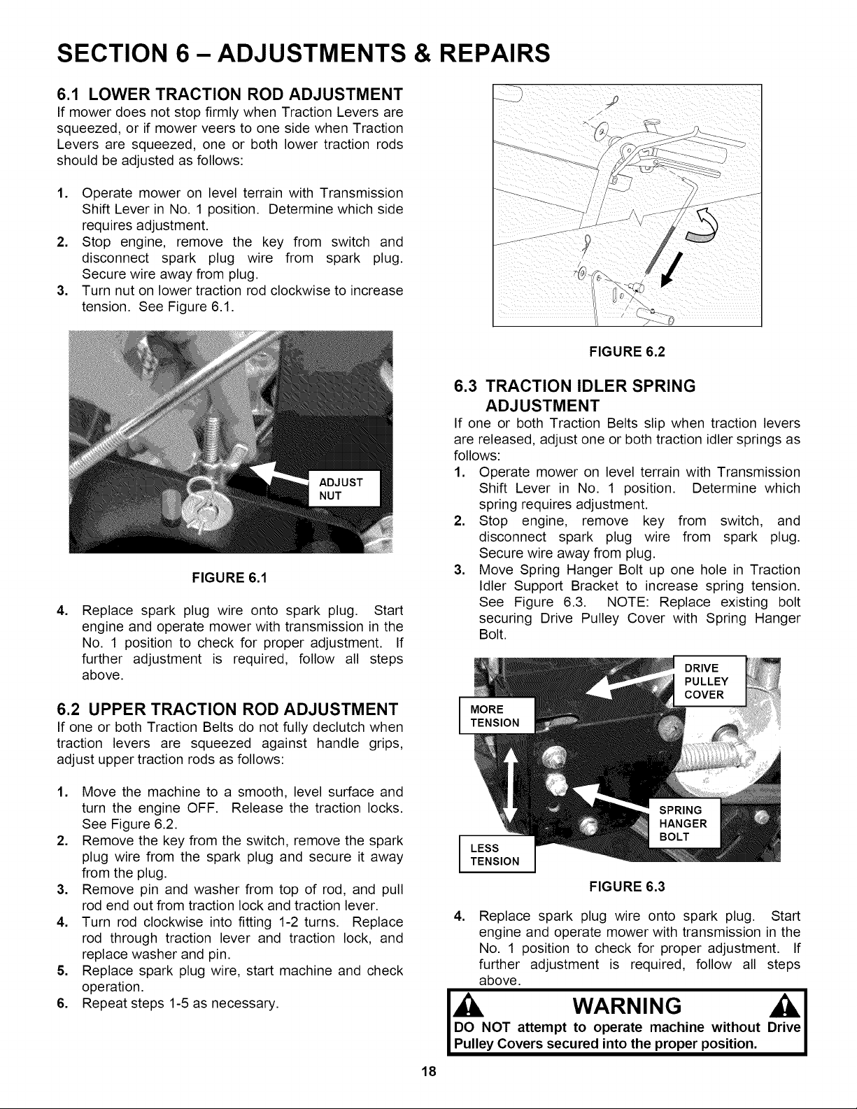
6.2 UPPER TRACTION ROD ADJUSTMENT
If one or both Traction Belts do not fully declutch when
traction levers are squeezed against handle grips,
adjust upper traction rods as follows:
1. Move the machine to a smooth, level surface and
turn the engine OFF. Release the traction locks.
See Figure 6.2.
2. Remove the key from the switch, remove the spark
plug wire from the spark plug and secure it away
from the plug.
3. Remove pin and washer from top of rod, and pull
rod end out from traction lock and traction lever.
4. Turn rod clockwise into fitting 1-2 turns. Replace
rod through traction lever and traction lock, and
replace washer and pin.
5. Replace spark plug wire, start machine and check
operation.
6. Repeat steps 1-5 as necessary.
18
FIGURE 6.2
6.3 TRACTION IDLER SPRING
ADJUSTMENT
If one or both Traction Belts slip when traction levers
are released, adjust one or both traction idler springs as
follows:
1. Operate mower on level terrain with Transmission
Shift Lever in No. 1 position. Determine which
spring requires adjustment.
2. Stop engine, remove key from switch, and
disconnect spark plug wire from spark plug.
Secure wire away from plug.
3. Move Spring Hanger Bolt up one hole in Traction
Idler Support Bracket to increase spring tension.
See Figure 6.3. NOTE: Replace existing bolt
securing Drive Pulley Cover with Spring Hanger
Bolt.
DRIVE
PULLEY
COVER
I
LESS
TENSION
FIGURE 6.3
4. Replace spark plug wire onto spark plug. Start
engine and operate mower with transmission in the
No. 1 position to check for proper adjustment. If
further adjustment is required, follow all steps
above.
j , WARNING Ori_ veI
DO NOT attempt to operate machine without "
Pulley Covers secured into the proper position,

SECTION 6- ADJUSTMENTS & REPAIRS
6.4 HANDLE HEIGHT ADJUSTMENT
The operator handle can be adjusted for operator
comfort as follows:
1. Loosen the two bolts on either side of
assembly. See Figure 6.4.
2. Raise or lower handle to desired height.
3. Retighten bolts securely.
handle
NOTE: After adjusting handle height, upper traction rods
may need to be adjusted.
LOOSEN
BOLTS
FIGURE 6.4
6.5 TRANSMISSION SHIFT INDICATOR
ADJUSTMENT
6.6 CUTTING HEIGHT ADJUSTMENT
The mower has two methods of adjusting cutting height:
1. Moving position of CUTTING BLADE on cutting
blade spindle shaft.
2. Moving position of CUTTING DECK.
6.6.1. CU-I-I-INGBLADE ADJUSTMENT
Each cutting blade assembly is equipped with six 1/4"
spacers - four below the blade spindle, and two above. To
change cutting height of Blades, move the Spacers from
under the Spindle Housing to above the Spindle Housing
Pulley. Each Spacer moved above the Spindle Housing
Pulley will provide an additional 1/4" of cutting height. DO
NOT put any Spacers below Blade. See Figures 6.6 and
6.7.
HEIGHT r,/_.j _/ AIR LIFT
;DJUSTRIN G I__
BLADE _ BLADNEI NG
BOLT
1. Loosen hardware securing Transmission Shift
Indicator Plate to machine. See Figure 6.5.
2. Move the Transmission Shift Lever to the neutral (N)
position.
3. Adjust the indicator plate until the 'N' is clearly
aligned clearly under the hole in the shift lever.
Then move the shift lever throughout the speed
range, making sure that all other gears are visible.
4. Tighten indicator hardware.
LOOSEN
HARDWARE
FIGURE 6.5
TIGHTEN TO 60-75 FOOT POUNDS
FIGURE 6.6
NOTE: Changing cutting height of blades does not
change the cutting deck ground clearance. If an
undesirable cutting pattern results, then cutting height
adjustment must be made by adjusting rear axle and
caster wheels.
Install Blades (Air Lift Up) with retaining hardware as
shown below and tighten to 60 to 75 ft.-Ibs. See Figure 6.7.
SPINDLE SPACERS
HOUSING _,_.__ ON TOP
PULLEY ,_,,,_ll,_ r"_.
,'"'"_ l; _ SPoIuNDILN_
BLADE I [ SPACERS ON
/ / BOTTOM
• ,;...........; ,! ,,, J_...,..._
FIGURE 6.7
19
SECTION 6- ADJUSTMENTS & REPAIRS
WARNING
DO NOT attempt any maintenance, adjustments or
service with the engine running. Stop engine. Stop
blades. Lock Traction Levers. Remove key.
Disconnect spark plug wires from spark plugs and
secure wires away from spark plugs. Engine and
components are HOT. Avoid serious burns,allow all
partsto cool beforeworking on machine.
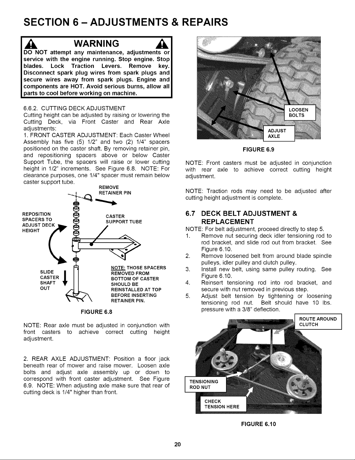
6.6.2. CUTTING DECK ADJUSTMENT
Cutting height can be adjusted by raising or lowering the
Cutting Deck, via Front Caster and Rear Axle
adjustments:
1. FRONT CASTER ADJUSTMENT: Each Caster Wheel
Assembly has five (5) 1/2" and two (2) 1/4" spacers
positioned on the caster shaft. By removing retainer pin,
and repositioning spacers above or below Caster
Support Tube, the spacers will raise or lower cutting
height in 1/2" increments. See Figure 6.8. NOTE: For
clearance purposes, one 1/4" spacer must remain below
caster support tube.
REMOVE
RETAINER PIN
ADJUST
AXLE
FIGURE 6.9
NOTE: Front casters must be adjusted in conjunction
with rear axle to achieve correct cutting height
adjustment.
NOTE: Traction rods may need to be adjusted after
cutting height adjustment is complete.
REPOSITION
SPACERS TO
CASTER
SUPPORT TUBE
NOTE: THOSE SPACERS
REMOVED FROM
BOTTOM OF CASTER
SHOULD BE
REINSTALLED AT TOP
BEFORE INSERTING
RETAINER PIN.
FIGURE 6.8
NOTE: Rear axle must be adjusted in conjunction with
front casters to achieve correct cutting height
adjustment.
6.7 DECK BELT ADJUSTMENT &
REPLACEMENT
NOTE: For belt adjustment, proceed directly to step 5.
1. Remove nut securing deck idler tensioning rod to
rod bracket, and slide rod out from bracket. See
Figure 6.10.
2. Remove loosened belt from around blade spindle
pulleys, idler pulley and clutch pulley.
3. Install new belt, using same pulley routing. See
Figure 6.10.
4. Reinsert tensioning rod into rod bracket, and
secure with nut removed in previous step.
5. Adjust belt tension by tightening or loosening
tensioning rod nut. Belt should have 10 Ibs.
pressure with a 3/8" deflection.
ROUTE AROUND
CLUTCH
2. REAR AXLE ADJUSTMENT: Position a floor jack
beneath rear of mower and raise mower. Loosen axle
bolts and adjust axle assembly up or down to
correspond with front caster adjustment. See Figure
6.9. NOTE: When adjusting axle make sure that rear of
cutting deck is 1/4" higher than front.
FIGURE 6.10
20
SECTION 6- ADJUSTMENTS & REPAIRS
WARNING
DO NOT attempt any maintenance, adjustments or
servicewith the engine running.Stop engine. Stop
blades. Lock Traction Levers. Remove key.
Disconnect spark plug wires from spark plugs and
secure wires away from spark plugs. Engine and
components are HOT. Avoid serious burns, allow
allpartsto cool beforeworking on machine.
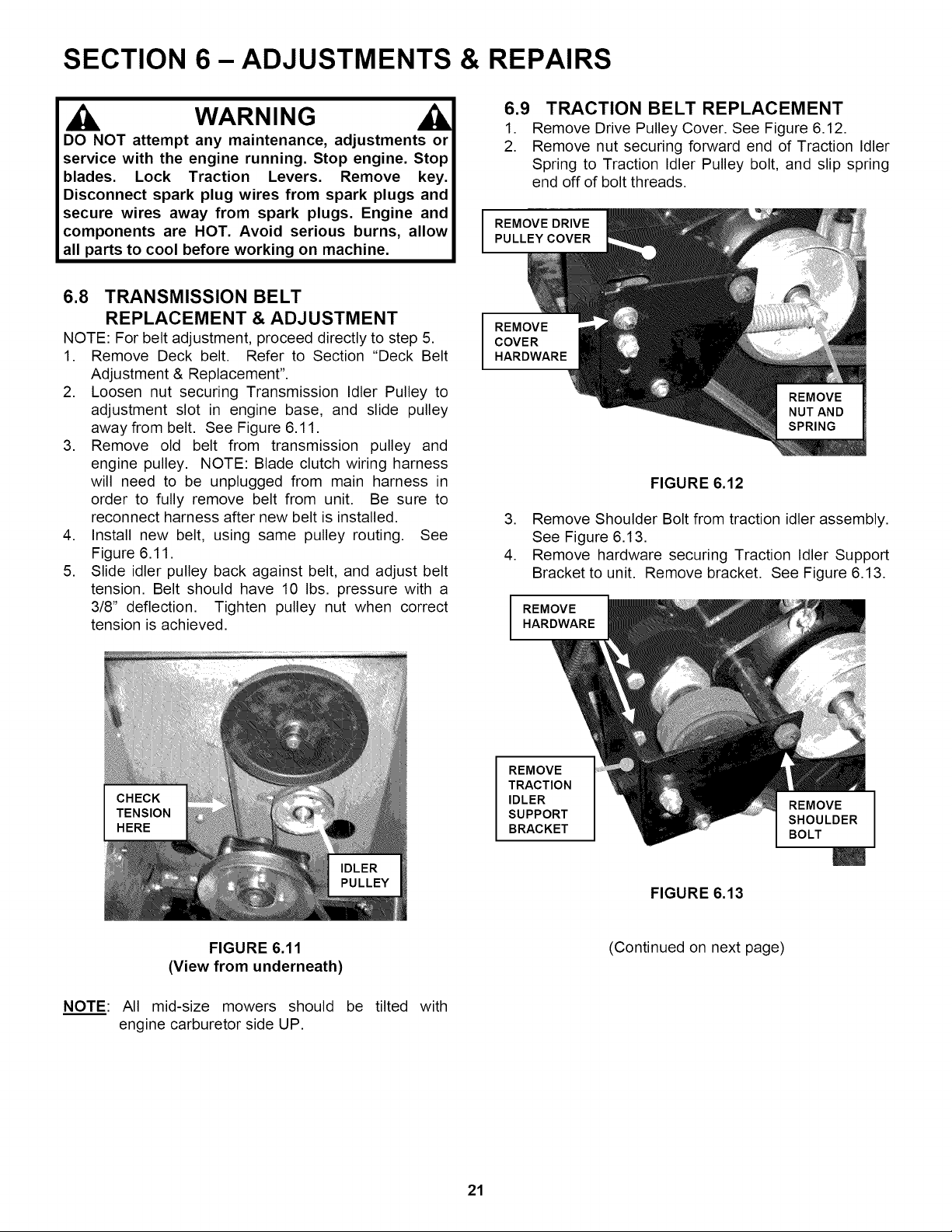
6.9 TRACTION BELT REPLACEMENT
1. Remove Drive Pulley Cover. See Figure 6.12.
2. Remove nut securing forward end of Traction Idler
Spring to Traction Idler Pulley bolt, and slip spring
end off of bolt threads.
REMOVE DRIVE
PULLEY COVER
6.8 TRANSMISSION BELT
REPLACEMENT & ADJUSTMENT
NOTE: For belt adjustment, proceed directly to step 5.
1. Remove Deck belt. Refer to Section "Deck Belt
Adjustment & Replacement".
2. Loosen nut securing Transmission Idler Pulley to
adjustment slot in engine base, and slide pulley
away from belt. See Figure 6.11.
3. Remove old belt from transmission pulley and
engine pulley. NOTE: Blade clutch wiring harness
will need to be unplugged from main harness in
order to fully remove belt from unit. Be sure to
reconnect harness after new belt is installed.
4. Install new belt, using same pulley routing. See
Figure 6.11.
5. Slide idler pulley back against belt, and adjust belt
tension. Belt should have 10 Ibs. pressure with a
3/8" deflection. Tighten pulley nut when correct
tension is achieved.
REMOVE
COVER
HARDWARE
FIGURE 6.12
3. Remove Shoulder Bolt from traction idler assembly.
See Figure 6.13.
4. Remove hardware securing Traction Idler Support
Bracket to unit. Remove bracket. See Figure 6.13.
I
REMOVE
HARDWARE
REMOVE
TRACTION
IDLER
SUPPORT
BRACKET
FIGURE 6.13
FIGURE 6.11
(View from underneath)
NOTE: All mid-size mowers should be tilted with
engine carburetor side UP.
(Continued on next page)
21
BOLT
SECTION 6- ADJUSTMENTS & REPAIRS
WARNING
DO NOT attempt any maintenance, adjustments or
servicewith the engine running.Stop engine. Stop
blades. Lock Traction Levers. Remove key.
Disconnect spark plug wires from spark plugs and
secure wires away from spark plugs. Engine and
components are HOT. Avoid serious burns, allow
allpartsto cool beforeworking on machine.
t
I RAISE
1/4- 1/2"
I
6.9 TRACTION BELT REPLACEMENT
(Continued)
5. Slide old wheel drive belt off pulleys. See Figure
6.14. NOTE: Drop belt down around wheel, and
roll mower over belt.
6. Replace belt, and reassemble removed
components in reverse order. Torque all hardware
(except nut securing spring to Traction Idler Pulley
bolt) to 20-30 ft-lbs. NOTE: Do not tighten Spring
Hanger hardware until Traction Idler Shoulder Bolt
has been replaced and tightened.
REMOVE BELT
FROM PULLEYS
LOOSEN SET
SCREW
FIGURE 6.15
6.11 REPLACEMENT PARTS
To retain the quality of your mower, use Genuine
SNAPPER Replacement Parts only! Contact your local
SNAPPER dealer for parts and service assistance. For
the correct part or information for your mower, always
mention Model and Serial Number of Power Unit and
Mower Attachment. We recommend returning your
mower to an authorized SNAPPER Dealer on a yearly
basis for inspection and addition of any new devices
which might upgrade the performance and safety of
your mower. For the nearest SNAPPER Dealer, check
the Yellow Pages under the heading LAWN MOWERS.
For Engine Parts and Service, look for the Engine
Manufacturer's Dealers under the heading ENGINES-
Gasoline. For transmission parts and service, look for
Tecumseh Engines & Transmission under Engines-
Gasoline.
FIGURE 6.14
NOTE: For belt adjustment, refer to Section "Traction
Idler Spring Adjustment".
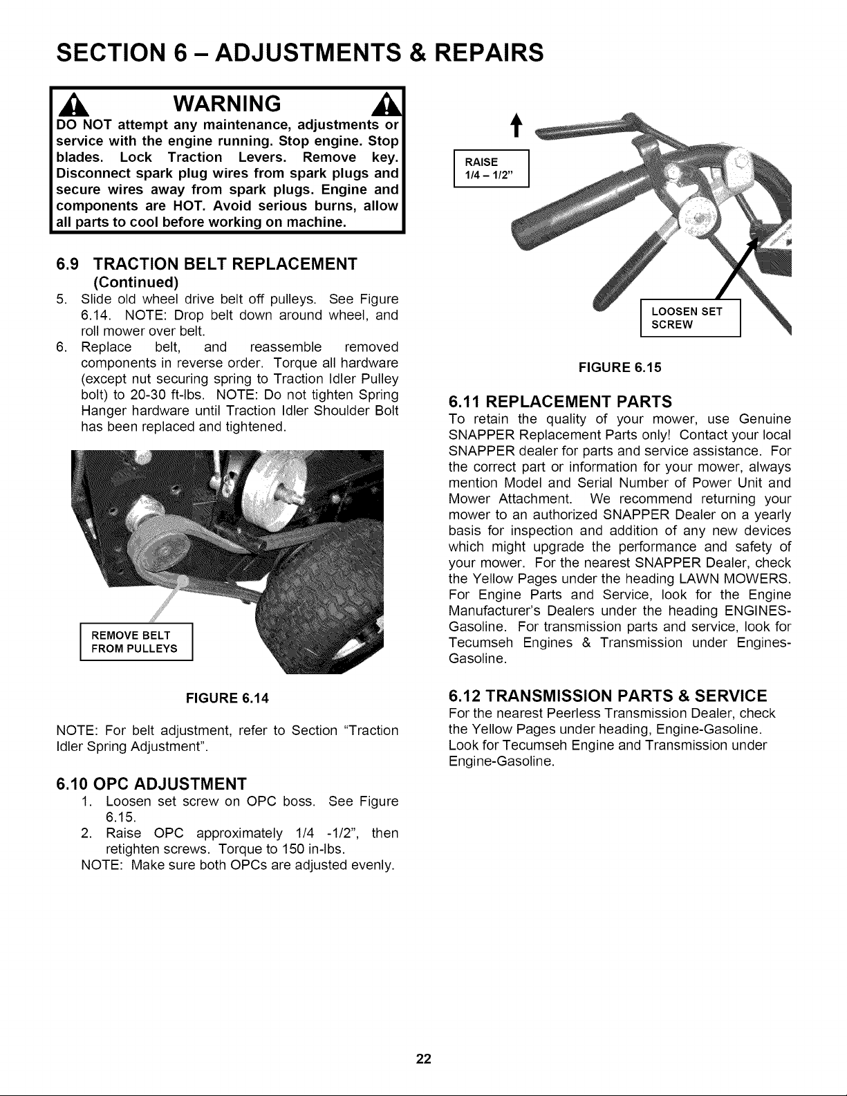
6.10 OPC ADJUSTMENT
1. Loosen set screw on OPC boss. See Figure
6.15.
2. Raise OPC approximately 1/4 -1/2", then
retighten screws. Torque to 150 in-lbs.
NOTE: Make sure both OPCs are adjusted evenly.
6.12 TRANSMISSION PARTS & SERVICE
For the nearest Peerless Transmission Dealer, check
the Yellow Pages under heading, Engine-Gasoline.
Look for Tecumseh Engine and Transmission under
Engine-Gasoline.
22
SECTION 6- ADJUSTMENTS & REPAIRS
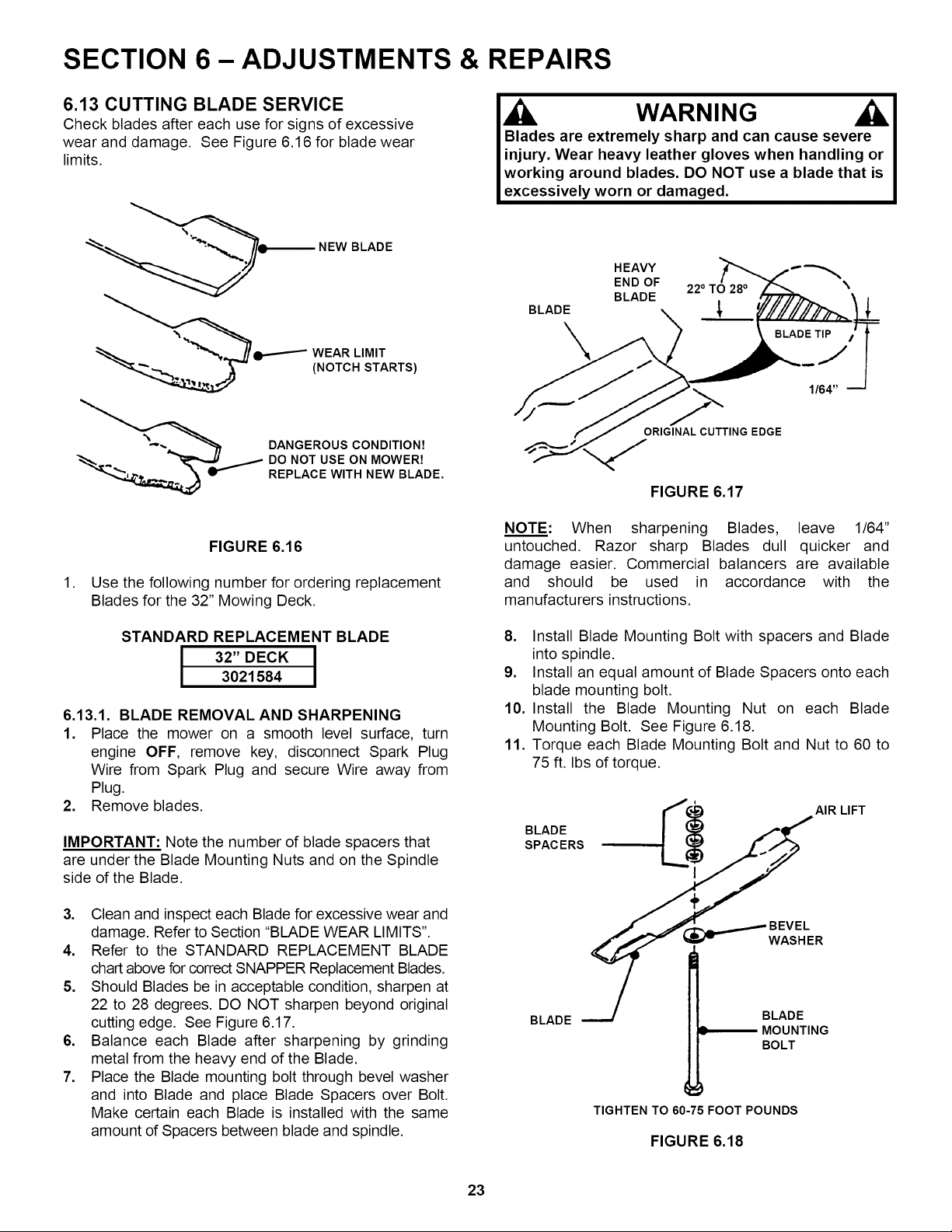
6.13 CUTTING BLADE SERVICE
Check blades after each use for signs of excessive
wear and damage. See Figure 6.16 for blade wear
limits.
q_--------- NEW BLADE
WEAR LIMIT
(NOTCH STARTS)
DANGEROUS CONDITION7
DO NOT USE ON MOWER7
REPLACE WITH NEW BLADE.
FIGURE 6.16
1. Use the following number for ordering replacement
Blades for the 32" Mowing Deck.
STANDARD REPLACEMENT BLADE
I I
3021584
6.13.1. BLADE REMOVAL AND SHARPENING
1. Place the mower on a smooth level surface, turn
engine OFF, remove key, disconnect Spark Plug
Wire from Spark Plug and secure Wire away from
Plug.
2. Remove blades.
IMPORTANT: Note the number of blade spacers that
are under the Blade Mounting Nuts and on the Spindle
side of the Blade.
3. Clean and inspect each Blade for excessive wear and
damage. Refer to Section "BLADE WEAR LIMITS".
4. Refer to the STANDARD REPLACEMENT BLADE
chart above for correct SNAPPER Replacement Blades.
5. Should Blades be in acceptable condition, sharpen at
22 to 28 degrees. DO NOT sharpen beyond original
cutting edge. See Figure 6.17.
6. Balance each Blade after sharpening by grinding
metal from the heavy end of the Blade.
7. Place the Blade mounting bolt through bevel washer
and into Blade and place Blade Spacers over Bolt.
Make certain each Blade is installed with the same
amount of Spacers between blade and spindle.
,Ji WARNING
Blades are extremely sharp and can cause severe
injury. Wear heavy leather gloves when handling or
working around blades. DO NOT use a blade that is
excessively worn or damaged.
BLADE
HEAVY
END OF
BLADE
22 ° TO 28 °
\
ORIGINAL CUTTING EDGE
FIGURE 6.17
NOTE: When sharpening Blades, leave 1/64"
untouched. Razor sharp Blades dull quicker and
damage easier. Commercial balancers are available
and should be used in accordance with the
manufacturers instructions.
8. Install Blade Mounting Bolt with spacers and Blade
into spindle.
9. Install an equal amount of Blade Spacers onto each
blade mounting bolt.
10. Install the Blade Mounting Nut on each Blade
Mounting Bolt. See Figure 6.18.
11. Torque each Blade Mounting Bolt and Nut to 60 to
75 ft. Ibs of torque.
_"¢_'__ AIR LIFT
L$
I
÷
BEVEL
R
BLADE '-"-/ BLADE
MOUNTING
BOLT
TIGHTEN TO 60-75 FOOT POUNDS
FIGURE 6.18
23
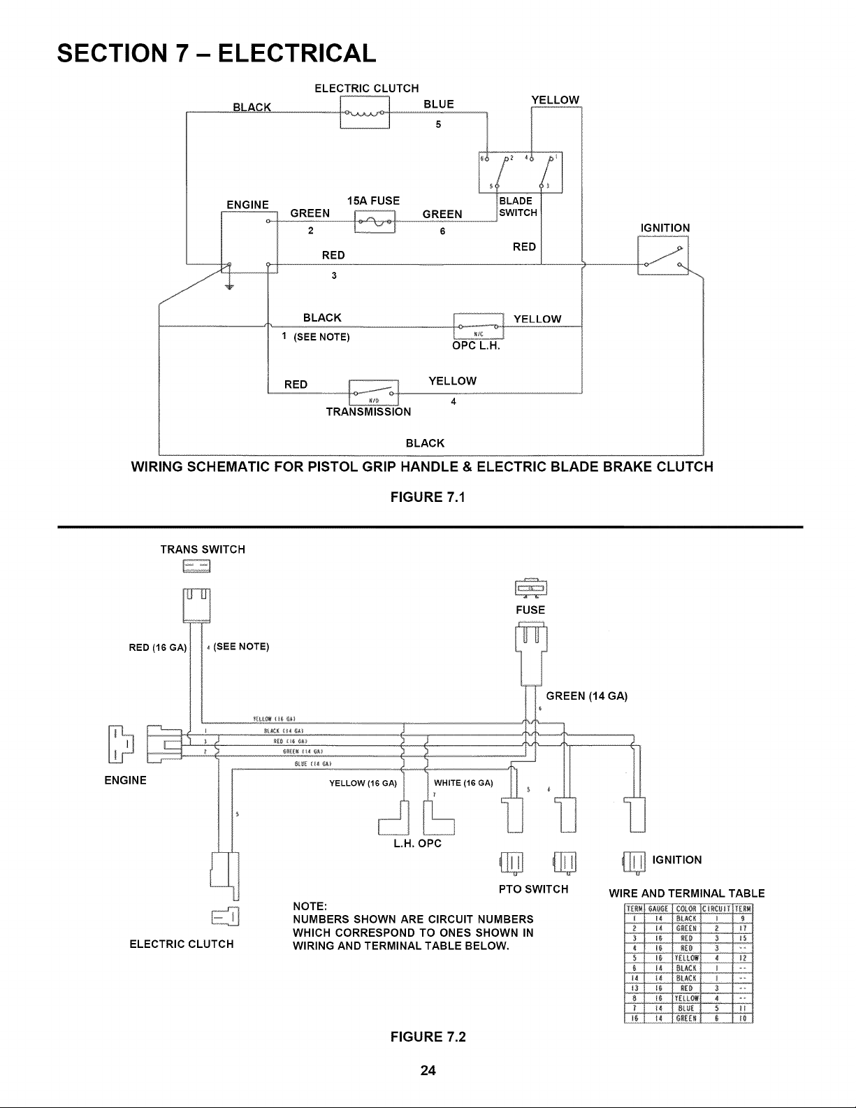
SECTION 7 - ELECTRICAL
BLACK
ELECTRIC CLUTCH
BLUE
5
YELLOW
ENGINE
15A FUSE
GREEN GREEN
2 6
RED
RED
BLACK
1 (SEE NOTE)
OPC L.H.
YELLOW
RED YELLOW
4
TRANSMISSION
IGNITION
BLACK
WIRING SCHEMATIC FOR PISTOL GRIP HANDLE & ELECTRIC BLADE BRAKE CLUTCH
FIGURE 7.1
TRANS SWITCH
RED (16 GA
ENGINE
--T-J
, (SEE NOTE)
ELECTRIC CLUTCH
YELLOW (1
L.H. OPC
FUSE
REEN (14 GA)
_ IGNITION
PTO SWITCH
NOTE:
NUMBERS SHOWN ARE CIRCUIT NUMBERS
WHICH CORRESPOND TO ONES SHOWN IN
WIRING AND TERMINAL TABLE BELOW.
WIRE AND TERMINAL TABLE
14 BHJ[ 5 M
FIGURE 7.2
24
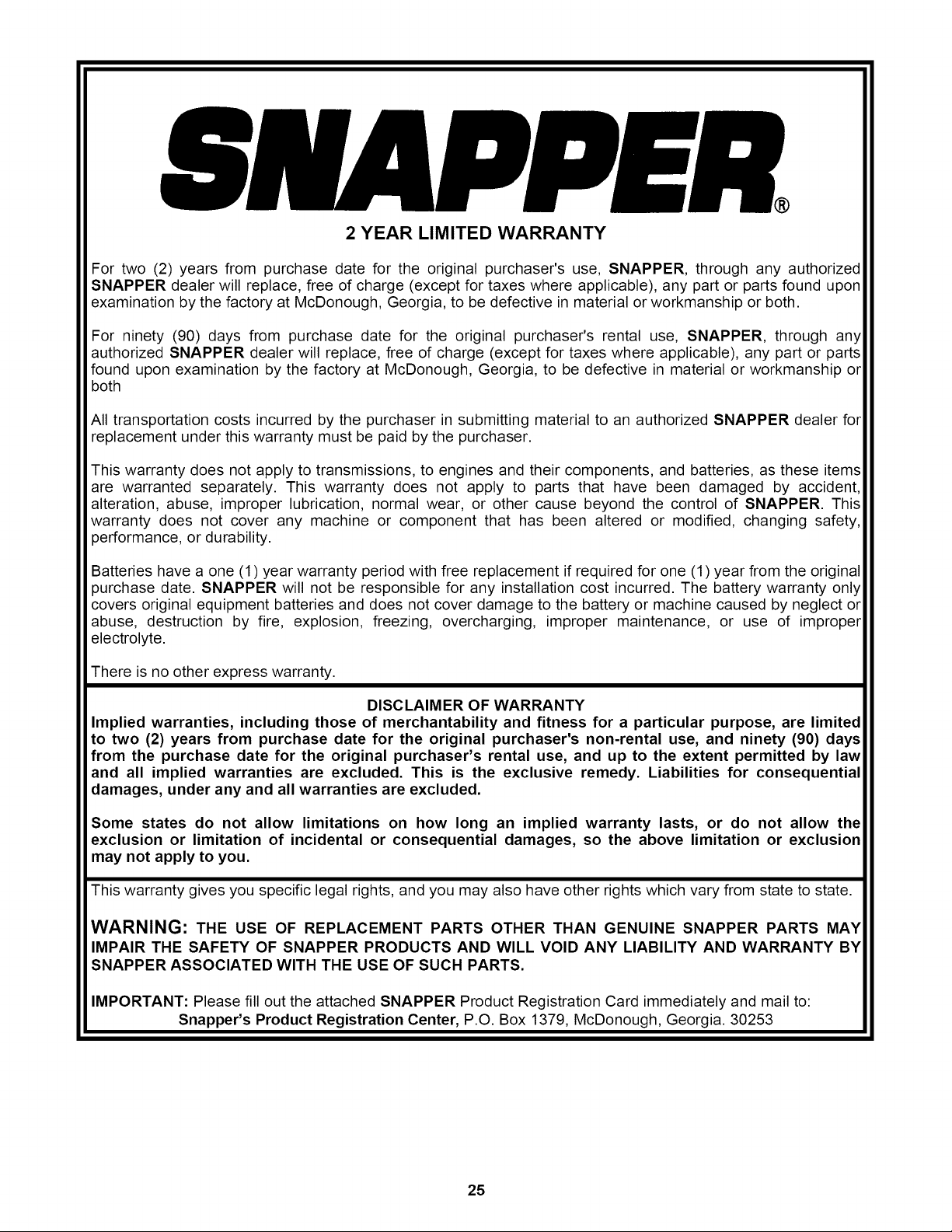
2 YEAR LIMITED WARRANTY
For two (2) years from purchase date for the original purchaser's use, SNAPPER, through any authorized
SNAPPER dealer will replace, free of charge (except for taxes where applicable), any part or parts found upon
examination by the factory at McDonough, Georgia, to be defective in material or workmanship or both.
For ninety (90) days from purchase date for the original purchaser's rental use, SNAPPER, through any
authorized SNAPPER dealer will replace, free of charge (except for taxes where applicable), any part or parts
found upon examination by the factory at McDonough, Georgia, to be defective in material or workmanship or
both
All transportation costs incurred by the purchaser in submitting material to an authorized SNAPPER dealer for
replacement under this warranty must be paid by the purchaser.
This warranty does not apply to transmissions, to engines and their components, and batteries, as these items
are warranted separately. This warranty does not apply to parts that have been damaged by accident,
alteration, abuse, improper lubrication, normal wear, or other cause beyond the control of SNAPPER. This
warranty does not cover any machine or component that has been altered or modified, changing safety,
performance, or durability.
Batteries have a one (1) year warranty period with free replacement if required for one (1) year from the original
purchase date. SNAPPER will not be responsible for any installation cost incurred. The battery warranty only
covers original equipment batteries and does not cover damage to the battery or machine caused by neglect or
abuse, destruction by fire, explosion, freezing, overcharging, improper maintenance, or use of improper
electrolyte.
There is no other express warranty.
DISCLAIMER OF WARRANTY
Implied warranties, including those of merchantability and fitness for a particular purpose, are limited
to two (2) years from purchase date for the original purchaser's non-rental use, and ninety (90) days
from the purchase date for the original purchaser's rental use, and up to the extent permitted by law
and all implied warranties are excluded. This is the exclusive remedy. Liabilities for consequential
damages, under any and all warranties are excluded.
Some states do not allow limitations on how long an implied warranty lasts, or do not allow the
exclusion or limitation of incidental or consequential damages, so the above limitation or exclusion
may not apply to you.
This warranty gives you specific legal rights, and you may also have other rights which vary from state to state.
WARNING: THE USE OF REPLACEMENT PARTS OTHER THAN GENUINE SNAPPER PARTS MAY
IMPAIR THE SAFETY OF SNAPPER PRODUCTS AND WILL VOID ANY LIABILITY AND WARRANTY BY
SNAPPER ASSOCIATED WITH THE USE OF SUCH PARTS.
IMPORTANT: Please fill out the attached SNAPPER Product Registration Card immediately and mail to:
Snapper's Product Registration Center, P.O. Box 1379, McDonough, Georgia. 30253
25

SNAPPER PRODUCT REGISTRATION FORM
IMPORTANT: KEEP THIS INFORMATION FOR YOUR PERSONAL RECORDS
(Complete the following information on your Snapper purchase)
Model Number
Serial Number
Date of Purchase
Retailer
Retailer's Phone Number
It is very important that you register your purchase with Snapper to ensure
warranty coverage. Please mail your product registration card to:
Snapper at P.O. Box 1379, McDonough, Georgia 30253.
Or you may register on line at www.snapper.com.
You can contact us at our web site or if you would like to speak with a Customer
Service Representative. Call us at the Snapper Customer Relations Center. For
faster service please have your Serial Number and Model Number available.
Call the Snapper Customer Relations Center at 1-800-935-2967.
26

PRIMARY MAINTENANCE
®
vs.DIRT I
an
illustration of
how dirt can
ge your
engine & how
reasonable
maintenance
can protect it!
Snapper uses the best avail-
able engines and components
in their products in order to
provide long, satisfactory
service. However, proper
care is essential In
prolonging engine life. Dirt
Is your engine's enemy
number 11
The engine on your Snapper
product spends Its entire life
operating close to the ground at
high speed creating a virtual
storm of dust and dirtl
27

PRIMARY MAINTENANCE
gulp about 12
gallons of air for
every gallon of
used. Because of
its working environ-
ment, the air avaUable
to your Snapper engine Is "
heavily saturated with air-
borne dirt particles.
__Knowing that dirt will
quickly ruin an engine,
", manufacturers equip their
engines with extremely
efficient air cleaners to
filter out the harmful dirt.
As the dirt parUcles are stopped,
they build up and begin to clog
the outside of the filter. This
reduces the amount of air
available to the engine and causes
an over-rich fuel mixture which re-
suits In the following adverse
effects:
An Improperly serviced, dirt
clogged air cleaner will:
1. Increase fuel consumption
2. cause power loss
3. result In hard starting
4. create smoke from unburned
fuel
5. produce carbon build-up
Internally
6. foul spark plug electrodes
7. score cylinder walls
8. burn valves
g. wear out the engine pre-
maturely
10. COST YOU MONEY!
Damage caused by a poorly serviced air
cleaner is not covered under the engine
warranties. So, save yourself unnecessary
expenses and undue aggravation by keeping
the afr cleaner properly serviced at the Intervals
specified In the engine owner's manual.
It doesn't take long to service an air cleaner.
Follow the specific instructions In the engine
owner's manual for the type filter used. Pre-
vent dirt from falling Into the carburetor Intake
when servicing your air cleaner• Make sure
components are Installed In correct sequence
after servicing to prevent unfiltered air from
entering the engine. Some servicing hints on
several common types are:
28
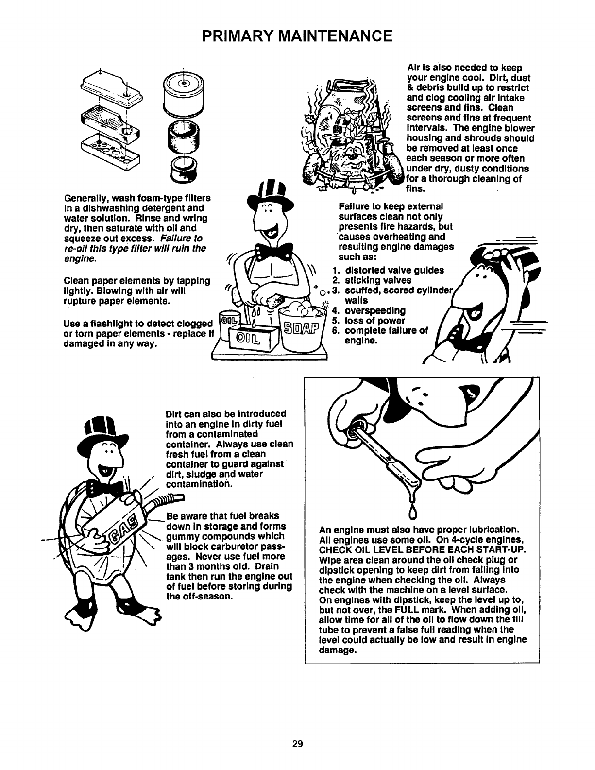
PRIMARY MAINTENANCE
Generally, wash foam-type filters
In a dishwashlng detergent and
water solution. Rinse and wring
dry, then saturate with oil and
squeeze out excess. Failure to
re-oil this type filter will ruin the
engine.
Clean paper elements by tapping
lightly. Blowing with air will
rupture paper elements.
Use a flashlight to detect clogged
or torn paper elements - replace If
damaged in any way.
Air is also needed to keep
your engine cool. Dirt, dust
& debris build up to restrict
and clog cooling air Intake
screens and fins. Clean
screens and fins at frequent
Intervals. The engine blower
housing and shrouds should
be removed at least once
each season or more often
l under dry, dusty conditions
for a thorough cleaning of
fins.
Failure to keep external
surfaces clean not only
presents fire hazards, but
causes overheating and
resulting engine damages
such as:
1. distorted valve guides
2. sticking valves
t ° o. 3. scuffed, scored
,,,. walls
4. overspeedlng
5. loss of power
6. complete failure of
engine.
Dirt can also be introduced
into an engine In dirty fuel
from a contaminated
container. Always use clean
fresh fuel from a clean
container to guard against
dirt, sludge and water
contamination.
Be aware that fuel breaks
down in storage and forms
gummy compounds which
will block carburetor pass-
ages. Never use fuel more
than 3 months old. Drain
tank then run the engine out
of fuel before storing during
the off-season.
An engine must also have proper lubrication.
All engines use some oil. On 4-cycle engines,
CHECK OIL LEVEL BEFORE EACH START-UP.
Wipe area clean around the oll check plug or
dipstick opening to keep dirt from falling Into
the engine when checking the oil. Always
check with the machine on a level surface.
On engines with dipstick, keep the level up to,
but not over, the FULL mark. When adding oil,
allow time for all of the oll to flow down the fill
tube to prevent a false full reading when the
level could actually be low and result In engine
damage.
29
PRIMARY MAINTENANCE
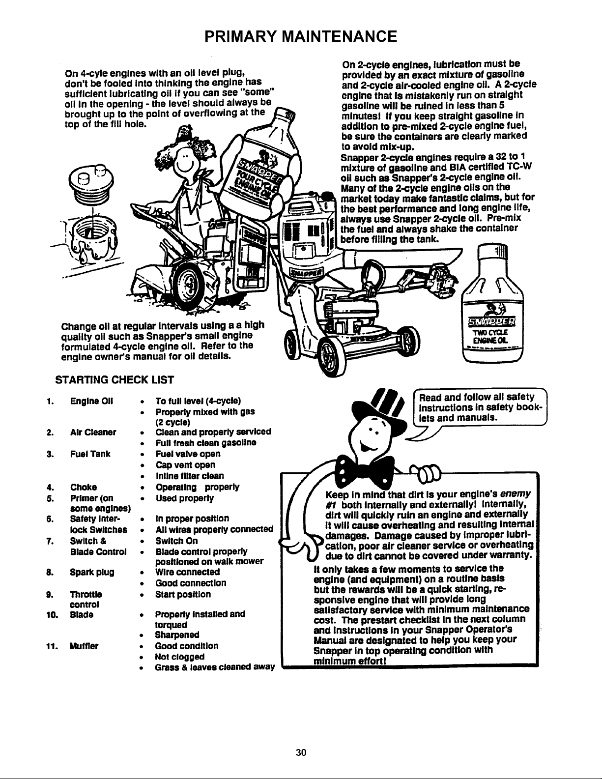
On 4-cyle engines with an oil level plug,
don't be fooled into thinking the engine has
sufficient lubricating oil if you can see "some"
oil in the opening - the level should always be
brought up to the point of overflowing at the
top of the fill hole.
I
On 2-cycle engines, lubrication must be
provided by an exact mixture of gasoline
and 2-cycle air-cooled engine oil A 2-cycle
engine that Is mistakenly run on straight
gasoline will be ruined in less than 5
mlnutesl If you keep straight gasoline in
addition to pre-mixed 2-cycle engine fuel,
be sure the containers are clearly marked
to avoid mix-up.
Snapper 2-cycle engines require a 32 to 1
mixture of gasoline and BIA certified TC-W
oil such as Snapper's 2-cycle engine o11.
Many of the 2-cycle engine oils on the
market today make fantastic claims, but for
the best performance and long engine life,
always use Snapper 2-cycle oil Pre-mix
the fuel and always shake the container
before filling the tank.
Change oil at regular Intervals using a a high
quality oil such as Snapper's small engine
formulated 4-cycle engine o11. Refer to the
engine owner's manual for oil details.
STARTING CHECK LIST
1. Engine OII
2. Air Cleaner
3. Fuel Tank
4. Choke
5. Primer (on
some engines)
6. Safety Inter-
lock Switches
7. Switch &
Blade Control
8. Spark plug
9. Throttle
control
10. Blade
11. Muffler
• To full level (4-cycle)
• Properly mixed with gas
(2 cycle)
• Clean and properly serviced
• Full freshclean gasoline
• Fuelvalve open
• Capvent open
• Inlinefilter clean
• Operating properly
• Used properly
• In proper position
• All wires properly connected
• Switch On
• Bladecontrol propedy
positionedon walk mower
• Wire connected
• GOOdconnection
• Start position
• Properly installed end
torqued
• Sharpened
• Good condition
• Not clogged
• Grass & leaves cleaned away
and follow all safety
Instructions in safety book-
Jlets and manuals.
Keep In mind that dirt Is your engine's enemy
#1 both Internally and externallyl Internally,
dirt will quickly ruin an engine and externally
It will cause overhcaUng and resulting internal
Damage caused by Improper lubrl- i
poor air cleaner service or overheating i
due to dirt cannot be covered under warranty.
It only takes a few moments to service the
engine (and equipment) on a routine baals
but the rewards will be a quick starting, re-
sponslve engine that will provide long
satisfactory service with minimum maintenance
cost. The prestart check,st In the next column
and Instructions in your Snapper Operator's
Manual am designated to help you keep your
Snapper In top operating condition with
minimum effortl
30

NOTES
31

Safety Instructions and Operator's Manual for
PRO SERIES
WALK BEHIND MOWER
SERIES 1
IMPORTANT
Snapper products are built using engines that meet or exceed all applicable emissions requirements on the
date manufactured. The labels on those engines contain very important emissions information and critical
safety warnings. Read, Understand, and Follow all warnings and instructions in this manual, the engine
manual, and on the machine, engine and attachments. If you have any questions about your Snapper product,
contact your local authorized Snapper dealer or contact Snapper Customer Service at Snapper, McDonough,
GA. 30253. Phone: (1-800-935-2967).
WARNING
BATTERY POSTS, TERMINALS AND RELATED ACCESSORIES CONTAIN LEAD AND LEAD COMPOUNDS,
CHEMICALS KNOWN TO THE STATE OF CALIFORNIA TO CAUSE CANCER AND BIRTH DEFECTS OR
OTHER REPRODUCTIVE HARM. WASH HANDS AFTER HANDLING.
WARNING
ENGINE EXHAUST, SOME OF ITS CONSTITUENTS, AND CERTAIN VEHICLE COMPONENTS CONTAIN OR
EMIT CHEMICALS KNOWN TO THE STATE OF CALIFORNIA TO CAUSE CANCER OR OTHER
REPRODUCTIVE HARM.
SNAPPER, McDonough,GA., 30253 U.S.A.
COPYRIGHT © 2005
SNAPPER - A Division of Simplicity Manufacturing, Inc.
ALL RIGHTS RESERVED
MANUAL No. 7-8176 (/.R. 1/24/05)
Printed in U.S.A.
32