Loading ...
Loading ...
Loading ...
3-Wire System for Electric Dryers-DO NOT use for Mobile Home Installations
_] Remove the screws securing the temfinal block
access cover and the strain relief mounting
bracket located on the back of the duer
upper corner.
V_ Attach the power cord neuu'al (center _4re)
conductor to the silver-colored center terminal
on the terminal block. Tighten the screw
securely.
[2-_Install a UL-approved su'ain relief into the power
cord entry"hole of the mounting bracket. Use
a su'ain relief which attaches to the mounting
bracket with a nut. Finger-tighten the nut only
at this time.
Vj] Thread a UL-approved 30A, 240V, 3#10 AWG
minimum copper conductor power cord through
the strain relief.
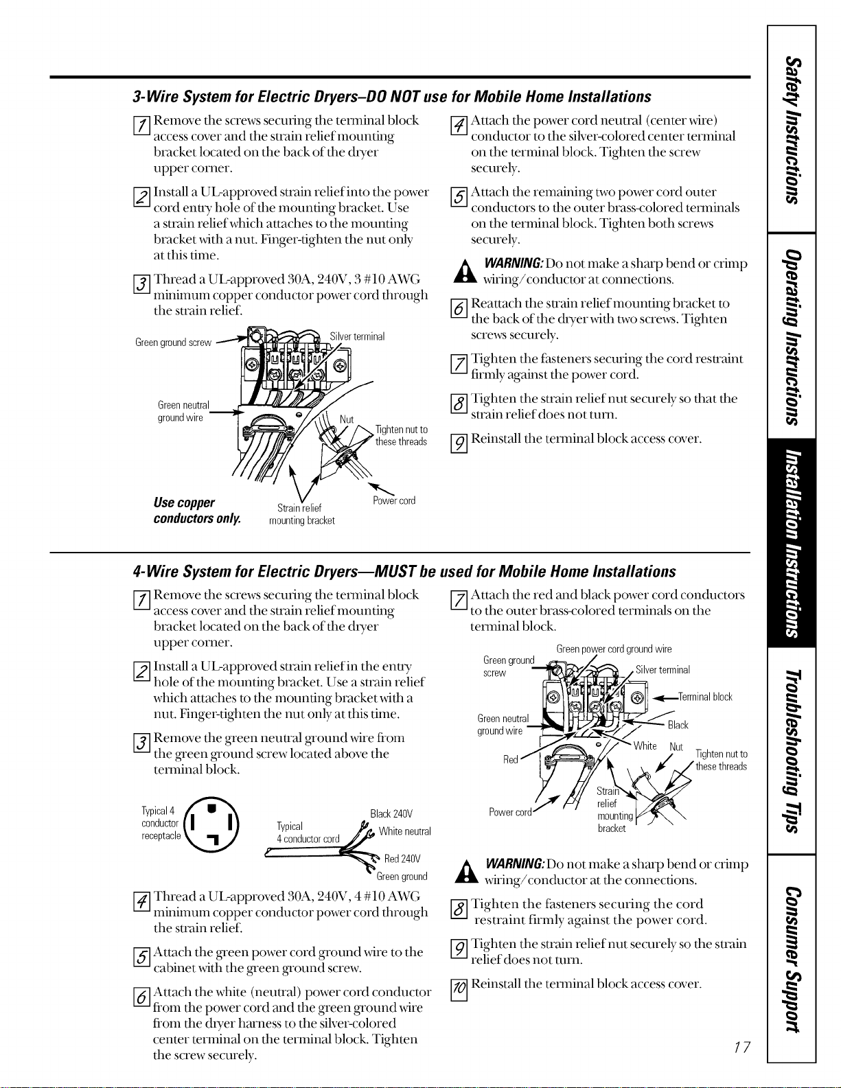
Green gl
Silverterminal
_] Attach the remaining two power cord outer
conductors to the ol{ter brass-colored temnnals
on the terminal block. Tighten both screws
securely.
WARIVING:Donot make a sharp bend or crimp
wiring/conductor at connections.
_-] Reattach the su'ain relief mounting bracket to
the back of the dryer _4th two screws" Tighten
screws securely.
[--_Tighten the f_steners securing the cord restraint
firl'nly against the power cor&
Green neutral
gr°undwire _//__ _/"(\Nu_
_/'/"'%lighten nut to
thesethreads
Use copper Strain elief Po_wercord
conductorsonly. mountingbracket
[_ Tighten the strain relief nut securely so that the
strain relief does not turn.
V_ Reinstall the temnnal block access cover.
4-Wire System for Electric Dryers--MUST be used for Mobile Home Installations
[7] emove the screws securing the temfinal block
access cover and the strain relief mounting
bracket located on the back of tim dtTer
upper corner.
[_-]Install a UL-approved smtin relief in the enuy
hole of the mounting bracket. Use a strain relief
which attaches to the mounting bracket with a
nut. Finger-tighten the nut only at this time.
V_]Remove the green neutral _'ound _4re from
the _een _ound screw located at)ove the
temfinal block.
Typical4
conductor| | | ]
receptacle_J
Black240V
Typical
,_- Whiteneutral
4conductorcord_
_,_ Red240V
" Greenground
V_ Thread a UL-approved 30A, 240V, 4#10 AWG
minimum copper conductor power cord fllrough
the strain relief.
_ ttach the _een power cord ground wire to the
cabinet with the _'een _'ound screw.
_-] Attach the white (neuu'al) power cord conductor
fi'om the power cord and the green ground _4re
fi'om the dryer harness to the silver-colored
center terminal on the terminal block. Tighten
the screw securely.
V-_ Attach the red and black power cord conductors
to the outer bra_ss-colored terminals on the
temfinal block.
Green power cord ground wire
Greenground _ /
screw Silverterminal
_'__'_J_ _._Terminal block
Greenneutral _ __'_,
groundwire mJ_,_)'S/_i_ --'_'_ Black
Red!,,,,,,____['/_White / Nut lighten nutto
_!_ _, _i¢'_ thesethreads
//..,. ,J/// Strain_._
'/'_" _ relief T .Y"/_&
Powercord/ _ [nounting[_)_ "_
bracket
WARNING:Donot make a sharp bend or crimp
wiring/conductor at the connections.
_-] Tighten the fasteners securing the cord
restraint firmly against the p[)wer cord.
_-_ Tighten the strain relief nut securely so the strain
relief does not tuna.
-0]Reinstall the terminal block access cover.
17
Loading ...
Loading ...
Loading ...