Loading ...
Loading ...
Loading ...
Installingthedryer.
Exhaust Ducting Length
The exhaust system should be inspected and cleaned
at least once a year _dth nomml usage. The more the
dUeT is used, the more often you should check the
exhaust system and vent hood for proper operation.
Kroofvents or louvered plenums are used, they must
be equivalent to a 4" dampered wall cap in regard to
resistance to aid]ow, prevention of back drafts and
maintenance required to prevent clogging.
• DONOTassemble the duct work with fksteners that
extend into the duct. They will serve as collection
points for lint.
• Ductworkwhich rims through an unheated area or
is near an air conditioning duct should be insulated
to reduce condensation and lint build-up.
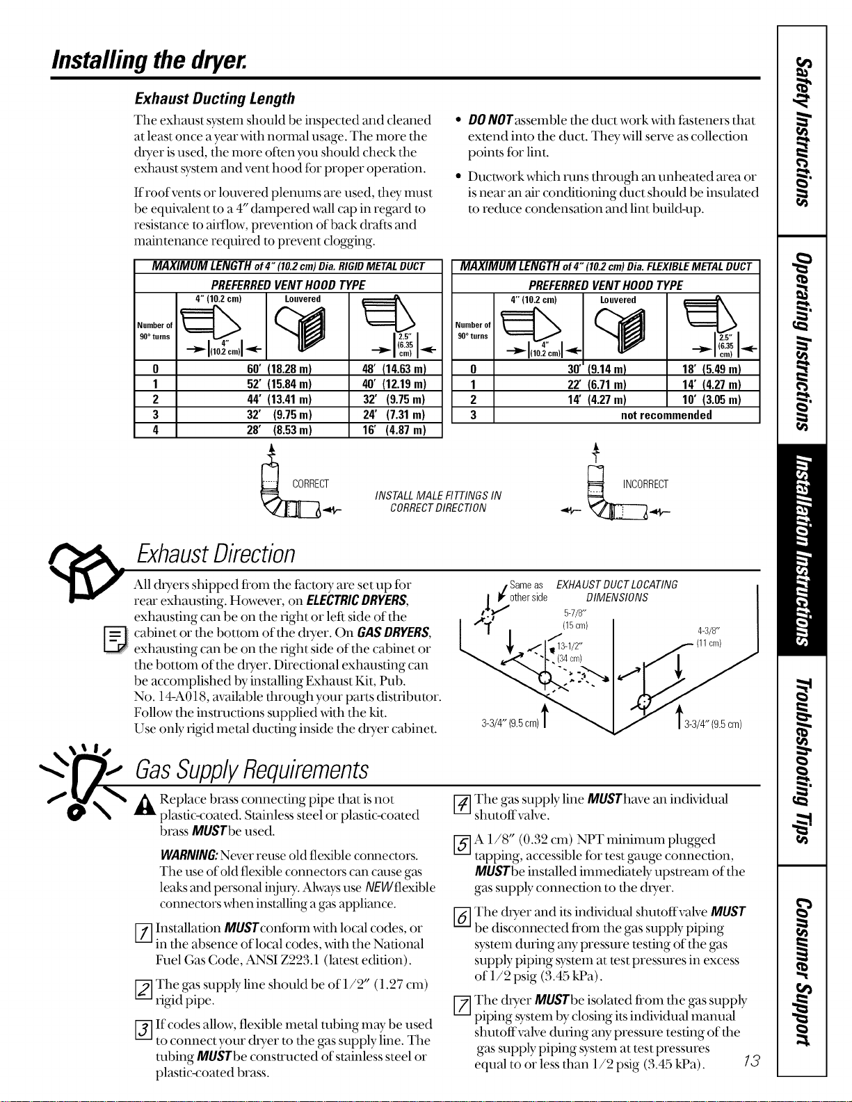
MAXIMUM LENGTH of4" 110.2cm)Dia. RIGIDMETALDUCT
PREFERREDVENTHOODTYPE
4" 110.2cm) Louvered
0 60' !10.28m)
1 52' (15.04m)
2 44' (13.41m) (9.75m)
3 32' (9.75m) (7.31m)
4 20' (0.53m) (4.87 m)
48' (14.63m)
40' (12.19m)
32'
24'
16'
MAXIMUM LENGTHof4" 110.2cm)Dia.FLEXIBLEMETALDUCT
PREFERREDVENTHOODTYPE
Number of
90° turns
0
1
2
3 notrecommended
INSTALL MALE FITTINGSIN
CORRECTDIRECTION
4" (102 cm) Louvered
30"!9.14m)
22' !6.71m)
14' (4.27m)
10' (5.49 m)
14' t4.27m)
10' (3.05m)
ExhaustDirection
All dryers shipped fi'om fl_efactory are set up for
rear exhausting. However, on ELECTRICDRYERS,
exhausting can be on the right or left side of the
cabinet or the bottom of the dryer. On GAS DRYERS,
exhausting can be on the right side of the cabinet or
the bottom of the dUeT. Directional exhausting can
be accomplished by installing Exhaust Kit, Pub.
No. 14-A018, available through your parts distributor.
Follow the instructions supplied _4th the kit.
Use only rigid metal ducting inside the dryer cabinet.
/ Same as EXHAUST DUCT LOCATING
| It" other side DIMENSIONS
(I,_ 5-7/8"
L (15cm) 4-3/8"
_/' 3-I/2" cm)
(34cm)
3-3/4"(9.5cm)t
gas SupplyRequirements
A Replace brass connecting pipe that is not
plastic-coated. Stainless steel or plastic-coated
brass MUSTbeused.
WARNING:Never reuse old flexible connectors.
The use of old flexible connectors can cm_segas
leaks and personal injury. Alwa}_use NEWflexible
connectors when installing a gas appliance.
Installation MUSTconibrm _dth local codes, or
in the absence of local codes, with the National
Fuel Gas Code, ANSI Z223.1 (latest edition).
The gas supply line should be of 1/2" 11.27 cm)
rigid pipe.
If codes allow, flexible metal tubing may be used
to connectyour dryer to the gas supply line. The
tubing MUSTbeconsu'ucted of stainless steel or
pla_stic-coated brass.
V_]The gas supply line MUSThave an indMdual
shut_ffvalve.
[_-]A 1/8" (0.32 cm) NPT minimum plugged
tapping, accessible for test gauge con_'lection,
MUSTbe installed immediately upstream of the
ga_ssuppb_ connection to the dryer.
V6-]The dryer and its indMdual shutoffvah;e MUST
be disconnected fi'om the gas supply piping
system during aW pressure testing of the gas
supply piping system at test pressures in excess
of 1/2 psig (3.45 kPa).
V_The dryer MUSTbe isolated from the gas supply
piping system by closing its indMdual manual
shutoffvalve during any pressure testing of the
gas supply piping system at test pressures
equal to or less than 1/2 psig (3.45 kPa). 13
Loading ...
Loading ...
Loading ...