Loading ...
Loading ...
Loading ...
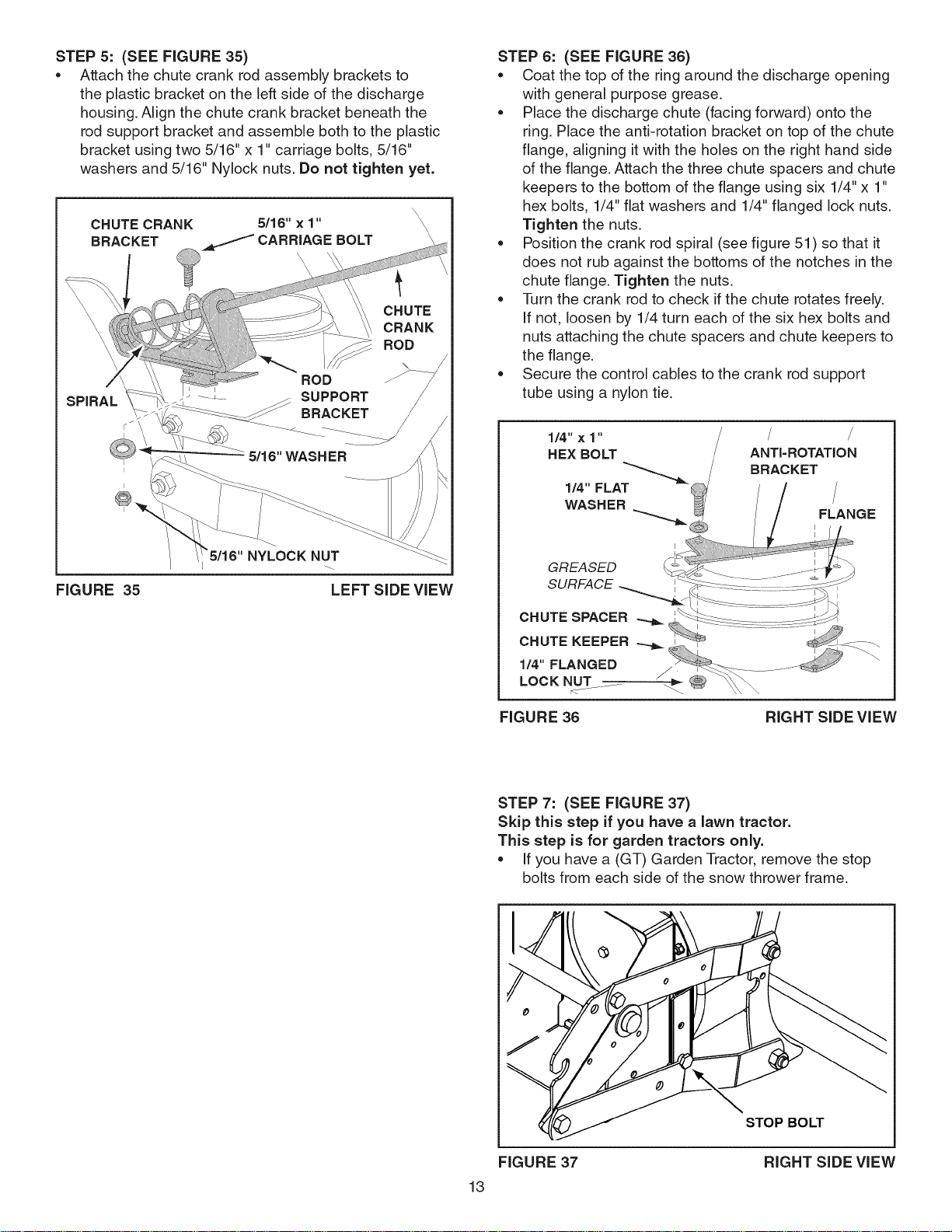
STEP5: (SEEFIGURE35)
Attachthechutecrankrodassemblybracketsto
theplasticbracketontheleftsideofthedischarge
housing.Alignthechutecrankbracketbeneaththe
rodsupportbracketandassemblebothtotheplastic
bracketusingtwo5/16"x1"carriagebolts,5/16"
washersand5/16"Nylocknuts.Donottightenyet.
\\
CHUTE CRANK 5/16" x 1" X
BRACKET CARRIAGE BOLT \
CHUTE
CRANK
ROD
SPIRAL
FIGURE 35 LEFT SiDE ViEW
STEP 6: (SEE FIGURE 36)
Coat the top of the ring around the discharge opening
with general purpose grease.
Place the discharge chute (facing forward) onto the
ring. Place the anti-rotation bracket on top of the chute
flange, aligning itwith the holes on the right hand side
of the flange. Attach the three chute spacers and chute
keepers to the bottom of the flange using six 1/4" x 1"
hex bolts, 1/4" fiat washers and 1/4" flanged lock nuts.
Tighten the nuts.
Position the crank rod spiral (see figure 51 ) so that it
does not rub against the bottoms of the notches in the
chute flange. Tighten the nuts.
Turn the crank rod to check ifthe chute rotates freely.
If not, loosen by 1/4 turn each of the six hex bolts and
nuts attaching the chute spacers and chute keepers to
the flange.
Secure the control cables to the crank rod support
tube using a nylon tie.
1/4";(1"
HEX BOLT ANTI=ROTATION
GREASED
SURFACE
CHUTE SPACER
CHUTE KEEPER
1/4" FLANGED
LOCK NUT
r<.............
FIGURE 36 RIGHT SiDE ViEW
STEP 7: (SEE FIGURE 37)
Skip this step if you have a lawn tractor.
This step is for garden tractors only.
If you have a (GT) Garden Tractor, remove the stop
bolts from each side of the snow thrower frame.
13
FIGURE 37
STOP BOLT
RIGHT SiDE ViEW
Loading ...
Loading ...
Loading ...