Loading ...
Loading ...
Loading ...
8
INITIAL INSTALLATION
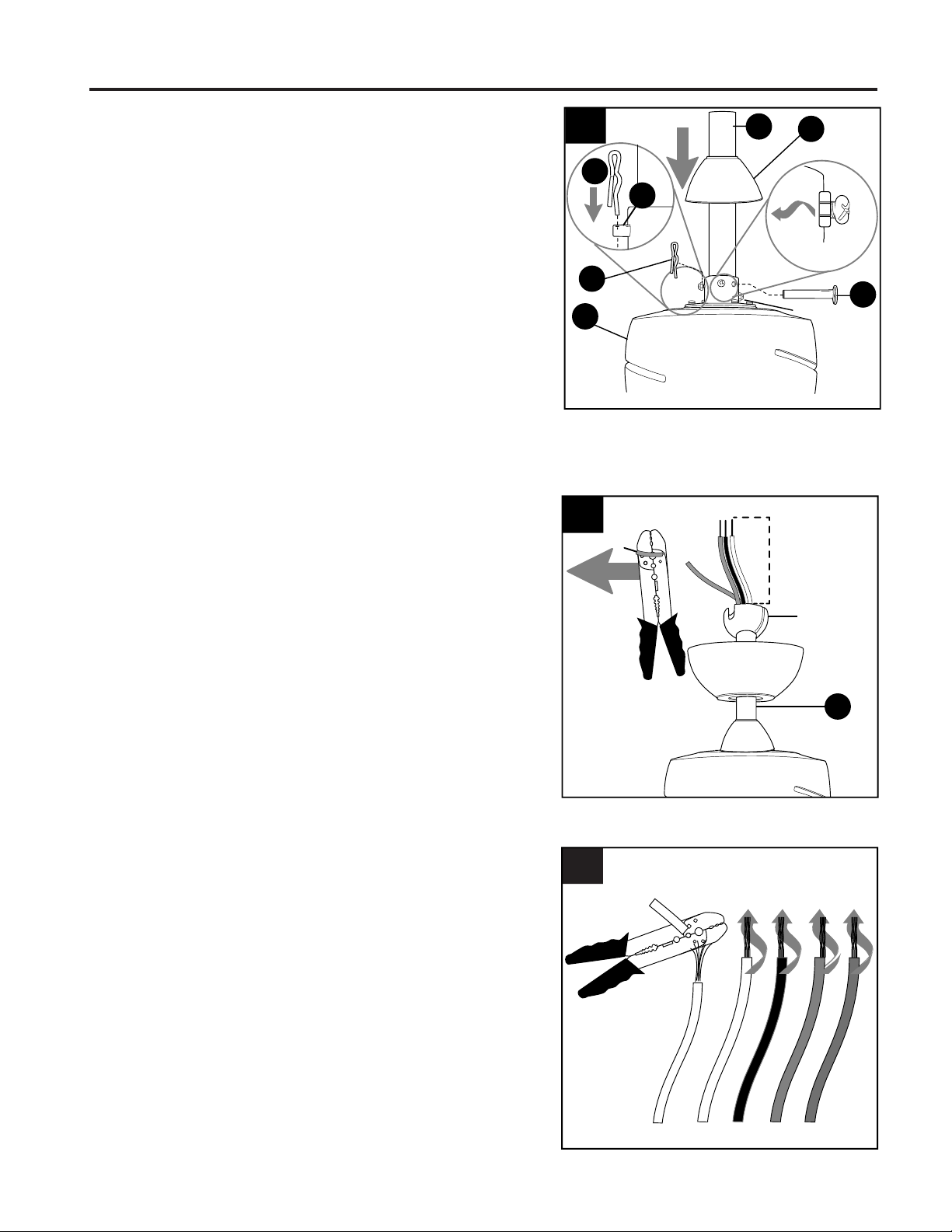
8.
Slip downrod (C) into motor assembly yoke, align
holes and re-install pin (D) and clip (E). Tighten
set screws in motor assembly yoke and then
tighten preassembled nuts on the set screws.
Then, slide yoke cover (H) down until it rests on
top of motor assembly (I).
8
C
I
H
D
E
Yoke
E
D
Set Screw
and Nut
Sideview
9.
If you decided to cut back the lead wires in Step 8,
strip 1/2 in. of insulation from end of each
wire -- WHITE, BLUE, PINK, GREY AND RED (if
applicable). Twist stripped ends of each strand of
wire within the insulation with pliers (not included).
Depending on the length of downrod you use, you
may need to cut the lead wires back to simplify
the wiring. If you decide to cut back the lead
wires, it is suggested you do so in the following
manner:
Take the lead wires and make sure you have
pulled them all the way through the top of the
downrod. Start at the TOP of the hanging ball on
the downrod and measure 8 in. of lead wire, then
cut the excess wire off with wire cutters (not
included).
NOTE: If you do not cut back the lead wires, Step
10 is not necessary and you may proceed to
Step 11 instead.
Hanging
Ball
9
C
8 in.
10.
10
Loading ...
Loading ...
Loading ...