Loading ...
Loading ...
Loading ...
11
FINAL INSTALLATION
1.
1
B
F
Knobs
G
Locate two canopy mounting screws (B) on
underside of mounting bracket (A) and remove
canopy mounting screw (B) closest to the open end
of the mounting bracket (A). Partially loosen the
other canopy mounting screw (B). Lift canopy (F) to
mounting bracket (A). Place rounded part of slotted
hole in canopy (F) over loosened canopy mounting
screw (B) and push up. Twist canopy (F) to lock.
Re-insert canopy mounting screw (B) that was
removed, then tighten both canopy mounting
screws (B).
Use arrows on inside of canopy cover (G) to locate
knobs on center ring of canopy cover (G). Slide
canopy cover (G) up to canopy (F), aligning knobs
on canopy cover (G) with openings in bottom of
canopy (F). Press up firmly on the canopy cover (G)
until it fits into the bottom of the canopy (F).
Twist
canopy cover (G) to lock.
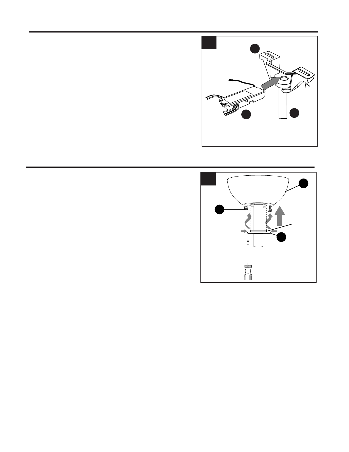
WIRING
3
Gently slide remote control receiver (Q) flat-side
up into mounting bracket (A). Turn spliced/taped
wires upward and gently push wires and wire
connectors (CC) into outlet box. Let antenna from
remote control receiver (Q) hang to the side.
NOTE: The remote control included with this fan
meets the following requirements:
a. Not for use with solid state fans.
b. Electrical rating: 120V / 60 Hz;
motor amps:1.25 MAX.
3.
Antenna
C
Q
A
Loading ...
Loading ...
Loading ...