Loading ...
Loading ...
Loading ...
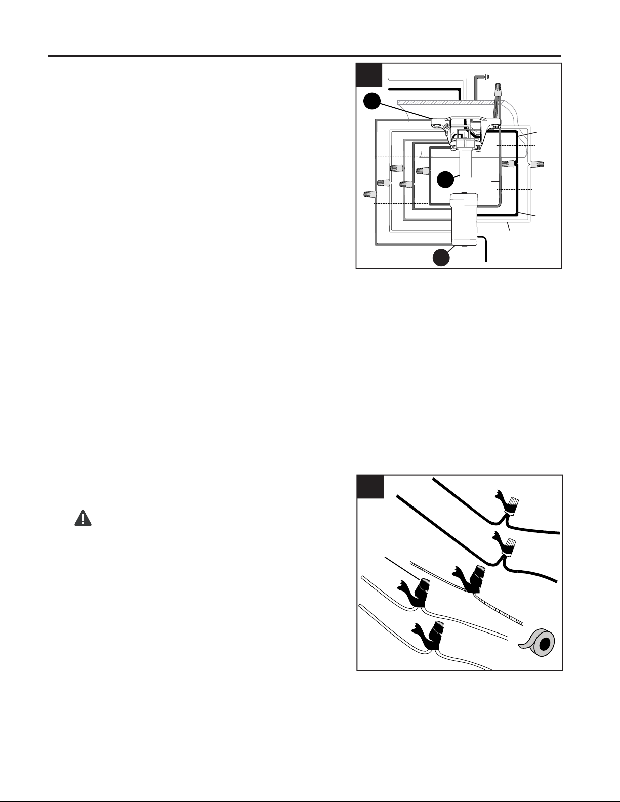
10
Wrap electrical tape (not included) around each
individual wire connector down to the wire.
WARNING: Make sure no bare wire or wire
strands are visible after making connections. Place
GREEN and WHITE connections on opposite side of
the outlet box from the BLACK and BLUE (if
applicable) connections.
2.
2
Connect all GROUND (GREEN) wires from fan
(on downrod (C), if applicable, mounting
bracket (A)) and remote control receiver (Q) to
BARE/GREEN supply wire from ceiling.
Connect BLACK wire (labeled AC IN L) from remote
control receiver (Q) to BLACK supply wire from ceiling.
Connect WHITE wire (labeled AC IN N) from remote
control receiver (Q) to WHITE supply wire from ceiling.
Connect RED wire (labeled TO MOTOR) from remote
control receiver (Q) to RED wire from motor
assembly (I).
Connect GRAY wire (labeled TO MOTOR) from remote
control receiver (Q) to GRAY wire from motor
assembly (I).
Connect PINK wire (labeled FOR MOTOR) from remote
control receiver (Q) to PINK wire from motor
assembly (I).
Connect BLUE wire (labeled FOR LIGHT L) from
remote control receiver (Q) to BLUE wire from motor
assembly (I).
Connect WHITE wire (labeled FOR LIGHT N) from
remote control receiver (Q) to WHITE wire from motor
assembly (I).
1.
WIRING
Q
1
WHITE SUPPLY WIRE
BLACK SUPPLY WIRE
PINK
RED
RED
GRAY
GRAY
PINK
WHITE
BLUE
BLUE
WHITE
BLACK
AC IN L
WHITE
AC IN N
WHITE
GROUND (GREEN OR BARE)
GROUND
(GREEN OR BARE)
BLACK
FROM
RECEIVER
FROM
FAN
FROM
RECEIVER
FROM
CEILING
C
A
GREEN/
GROUND
Wire
Connector
Loading ...
Loading ...
Loading ...