Loading ...
Loading ...
Loading ...
EN
20
Installation
www.bora.com
1
2
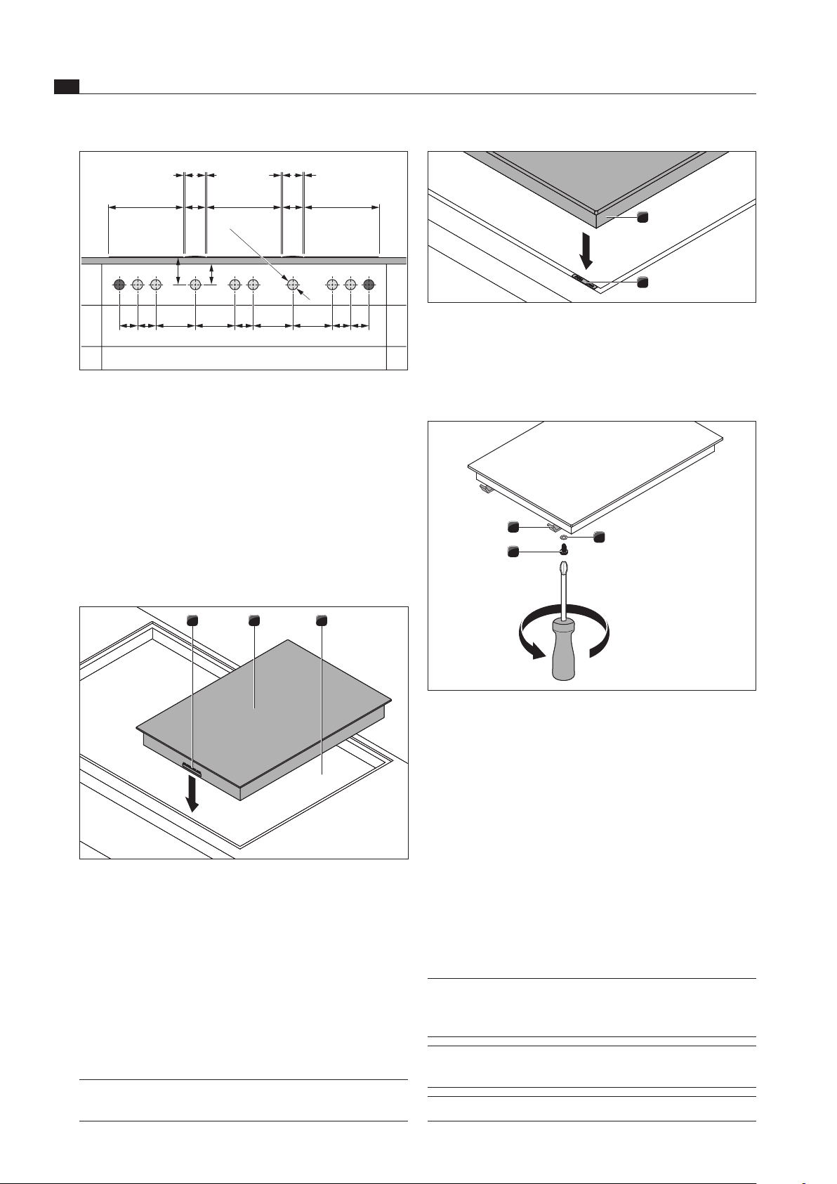
Fig. 5.15 Cooktop and height adjustment plates
[1] Cooktop
[2] Height adjustment plates
If applicable, insert the height adjustment plates [2].
1
3
2
Fig. 5.16 Mounting brackets
[1] Mounting bracket
[2] Washer
[3] Screw
Fasten the cooktop using the mounting brackets [1].
Tighten the mounting brackets with the screw [3] using
the washer [2] with max. 2 Nm.
Verify that the alignment is correct..
5.5.3 Installation rotated by 180°
Rotate the cooktop 180°.
For the installation, proceed as described above.
Change the installation direction in the configuration
menu (see Configuration menu).
INFO If installation is rotated by 180°, then the
connections for the control knobs and the
extraction system are at the rear.
INFO
If installation is rotated by 180°, the cooktop
display is automatically shown as rotated by 180°.
INFO Cables of sufficient length are provided.
≥70 ≥40
90 90 909090 196 196 196 196
370 370
370
110
1 1 1 1
110
Ø50 ±0,5
Fig. 5.13 Bore holes for 3 cooktops and 2 cooktop extractors
[1] Boreholes for socket (2x external)
[2] Bore holes for control knobs (8x)
[3] Cooktop (3x)
[4] Cooktop extractor (2x)
[5] Worktop
[6] Floor unit front panel
5.5.2 Installing the cooktop
Please note the position of the cooktop display.
Alternatively, the cooktop can be fitted rotated by
180° (see Installation rotated by 180°).
321
Fig. 5.14 Insert cooktop
[1] Connections for control knob and automatic extractor
function (front)
[2] Cooktop
[3] Worktop cut-out
Insert the cooktop [2] into the worktop cut-out [3].
Align the cooktop [2] exactly.
For a normal installation, please note that the
connections for the control knobs and the extraction
system [1] are at the front.
INFO The device connection should be at the rear. Use
the cable holders provided.
Loading ...
Loading ...
Loading ...