
Loading ...
Loading ...
Loading ...
8
INSTALLING THE WATER SUPPLY
Procedure for Testing Drain System
(both gravity and drain pump models)
Drain pump models have a safety feature that will interrupt power to the unit if a high-limit condition occurs to prevent
ooding. This safety feature can be initiated by a restriction in the drain system and will continue until high-limit condition
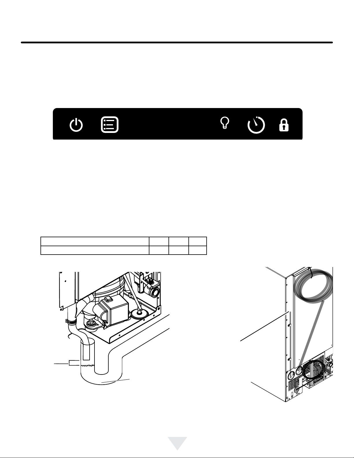
is corrected, at which time power will be restored to the unit. Power interruption can be detected when no icons are
visible in the display area of the user interface (Figure 10). Once power is returned, a startup chime will sound followed by
a self-test, and "OFF" should be visible in the display area.
hours
ICE
1 4 6 8
OFF CLEAN
DOOR
ECO
days
On/off Menu Light Delay timer Lock
Figure 10: User interface display during power interruption.
Once the drain line is plumbed, perform the following:
1. Plug the ice machine into 115v power supply.
2. Place unit in the nal installation location.
3. Turn the unit off via the user interface (display will indicate “OFF”). The drain pump will still be operational during off
mode if the unit has one.
4. Slowly pour 3-qts of water into the ice storage bin. All water should drain completely.
5. If water drains fully and without power interruption, the drain system has been successfully tested and further
installation of the ice machine can be continued.
6. If the water does not drain or a power interrupt occurs, check the following:
a. There are no kinks or restrictions in the drain line. (Note: Drain line needs to be cut to the required length and any
excess tubing should be removed to prevent possible restrictions).
b. Drain line was run according to the guidelines for maxiumum allowable rise and run as shown in the table below:
Rise Above Floor Level 8 ft. 9 ft. 10 ft.
Maxium Allowable Drain Line Length 20 ft. 15 ft. 10 ft.
b. Your drain line is plumbed into an open drain (Figure 11).
c. The vent tube on the back of the unit is open (Figure 12).
Air gap
between
end of
drain line
and top of
water level
Sanitary trap
Figure 11: Example of an open drain.
7. After checking the above requirements, repeat step 4 and verify the water drains completely without power interrup-
tion. If problems persist call a qualied service technician and/or plumber.
Drain pump vent
tube. Keep this
open to assure
air ows freely as
water enters the
pump reservoir.
Figure 12: Location of vent tube.
Loading ...
Loading ...
Loading ...