Loading ...
Loading ...
Loading ...
6
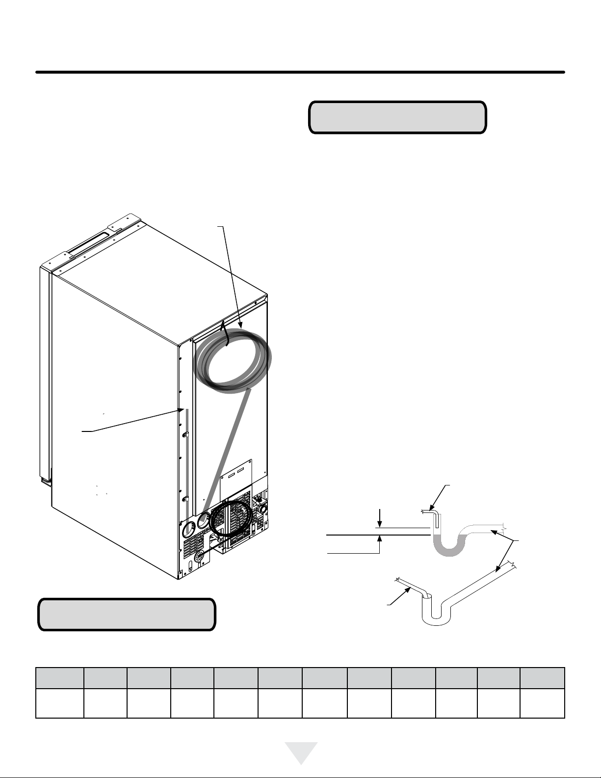
INSTALLING THE DRAIN PLUMBING
Figure 7
Drain pump
vent tube.
Keep this
open to
assure air
ows freely
as water
enters the
pump reser-
voir.
Drain line coiled and
secured to the back of the
cabinet. Uncoil, route to
an appropriate drain and
cut to length.
Rise in
feet (meters)
0 ft.
(0 m)
1 ft.
(0.3 m)
2 ft
(0.6 m)
3 ft.
(0.9 m)
4 ft.
(1.2 m)
5 ft.
(1.5 m)
6 ft.
(1.8 m)
7 ft.
(2.1 m)
8 ft.
(2.4 m)
9 ft.
(2.7 m)
10 ft.
(3.0 m)
Maximum
Run Allowed
feet (meters)
100 ft.
(30.5 m)
90 ft.
(27.4 m)
80 ft.
(24.4 m)
70 ft.
(21.3 m)
60 ft.
(18.6 m)
50 ft.
(15.2 m)
40 ft.
(12.2 m)
30 ft.
(9.1 m)
20 ft.
(6.1 m)
10 ft.
(3 m)
0 feet
(0 m)
Determine the maximum allowable run of your drain
hose:
For every 1 foot (0.31 meters) of rise, subtract 10 ft. (3.1 m)
from the maximum allowable run of 100 ft. (31 m).
If additional tubing beyond what is supplied is required, you
must use tubing with a minimum
3
⁄8" inner diameter and ap-
propriate tubing coupler and clamps.
NOTE
Allow
1
⁄4" (6.4 mm) drop per foot (30.5 cm) of run to assure
water drains from the tubing.
Table A
Procedure for testing drain system:
Drain pump models have a safety feature that will shut-off
power to the unit if a high-limit condition occurs to prevent
ooding. Typically resulting from a restricted drain line,
(water in-rush exceeds water pump out). Pump will contin-
ue to run until the high-limit condition is corrected, at which
time power will be restored to the unit.
Once the drain line is plumbed, perform the following:
1. Plug the ice machine into 115v power supply.
2. Place unit in the nal installation location.
3. Turn the unit off via the user interface touch-pad, (dis-
play will indicate “OFF”).
4. Slowly pour 3 quarts (2.8 liters) of water into the ice
storage bin. All water should drain completely.
5. If the water does not drain, or a power interrupt occurs,
check the following:
• Drain line was run according to the guidelines for
maximum allowable rise and run as shown in
Table A.
• There are no kinks or restrictions in the drain line.
• The vent tube on the back of the unit is open (see
Figure 7).
• Your drain line is plumbed into an open drain
(Figure 8).
After checking the above requirements, repeat step 4 and
verify the water drains completely without power interrup-
tion. If problems persist call a qualied service technician
and/or plumber.
NOTE
Water level
Sanitary
drain
Drain tubing
from ice machine
Drain tubing
from ice machine
2" (5.1 cm)
minimum
Figure 8 maintain 2"
gap as shown between
drain water level and
the end of the ice ma-
chine drain tubing.
Loading ...
Loading ...
Loading ...