Loading ...
Loading ...
Loading ...
-AIRSEAL
CONNECTIONS
HORIZONTAL
RIGHT
APPLICATION
SUPPORT
RAiL
BRACKET
DRAINpAN
HORIZONTAL RIGHT
SECONDARy DRAIN
HORIZONTAL RIGHT
A00071
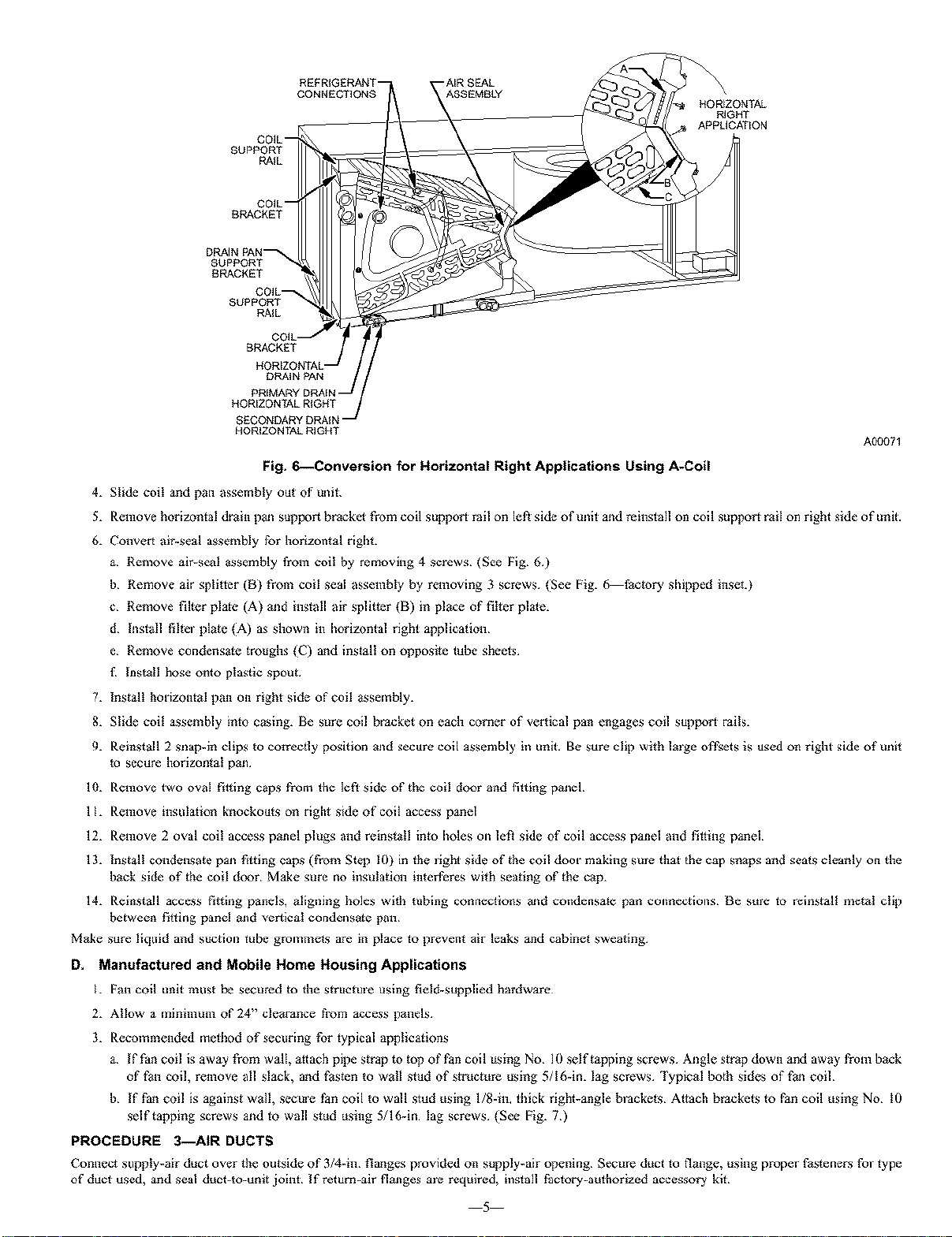
Fig. 6--Conversion for Horizontal Right Applications Using A-Coil
4. Slide coil and pan assembly out of mlg.
5. Remove horizomal drain pan support bracket from coil suppor_ rail on leR side of unit and reinslall on coil suppor_ rail on right side of unit.
6. Convert air-seal assembly for horizontal right.
a Remove air-seal assembly from coil by removing 4 screws (See Fig 6)
b Remove air splgler (B) Prom coil seal assembly by removing 3 screws {See Fig. 6 factor3, sldpped inseL}
c Remove filler plate (A) and install air splitter (B) in place of filter plale.
d Inslall fihm plate {A) as shown in I_orizontal right applicagon
e Remove condensate troughs {C) and install on opposite tube sheels
f Install hose onto plastic spout
7. Install hodzomal pan on right side of coil assembly.
8. Slide coil assembly into casing. Be sure coil bracket on e_h comer of vertical pan engages coil suppor_ raiix
9. Reinstall 2 snap-in clips to correcqy position and secure coil assembly in unit. Be sure clip with lmge ofl2sets is used on right side oPmlg
to secure horizontal pan
lO. Remove lwo oval fil_ing caps from the left side of the coil door and filfing panel
11. Remove insulation knockouts on right side of coil access panel
12. Remove 2 oval coil access panel plugs and reinstall into I_oles on leR side of coil access panel and filling panel
13. Install condensate pan fitting caps (from Sic't) 10) in lhe light side of gte coil door making sine that the cap snaps and seats cleanly on the
back side of the coil door Make sure no insulation interferes with seating of the cap.
14. Reinstall access fil_ing panels, aligning holes wgh tubing connections and condensate pan collnectiolls _e sure Io reinstall metal clip
between fitting panel and vertical condensate pan
Make sure liquid and suction tube grommets are in place Io prevent air leaks and cabinet sweating.
D, Manufactured and Mobile Home Housing Applications
1. Pan coil unit must be secured to the s_ructme using field-supplied hardware
2. Allow a minimum of 24" clearance from access panels
3. Recommended mefllod of securing for typical appticagons
a If Fan coil is away from walt, attach pipe s_rap to top of Pan coil using No 10 self tapping screws Angle strap down and away from back
of l_on coil, remove all slack, and l_osten to wail stud of s_ructure using 5/I6-in. lag screws Typical both sides of l_on coil
b If fan coil is against wail, secme Pan coil to wall stud using l/8-in, ddck right-angle b_ackets Attach brackels 1o fan coil using No 10
self tapping screws and m wall stud using 5/16-in lag screws {See Fig. 7)
PROCEDURE 3--AIR DUCTS
Connect supply-air duct over the (mtside of 3/d-in flanges provided on supply-air opening Secrete duct 1o flange, using proper Pasteners fol type
of duct used, and seal duct-to-unit joint If return-air flanges ale required, inslall Paclory-a_thorized accessory kit
5
Loading ...
Loading ...
Loading ...