Loading ...
POWER ENTRY_ SUPPLIED
OPTIONS_& SUPPLYDUCT
0t8,030-048 21dN.
060 24qN FRONT SERVICE
CLEARANCE
UPFLOW/DOWNFLOW -- -
SECONDARYO ,N
UPFLOW/DOWNFLOW J
PRIMARYDRAIN
SECONDARY DRAIN
PRIMARY DRAIN
ENTRY
OPTIONS
UNff A
018 12IN.
030 171N
036 191N
FIELD MODIFIED
A SIDE RETURN
LOCATION FOR
2 _/2_ SLOPE COIL
UNITS ONLY
FIELD SUPPLIED
RETURN PLENUM
A00415
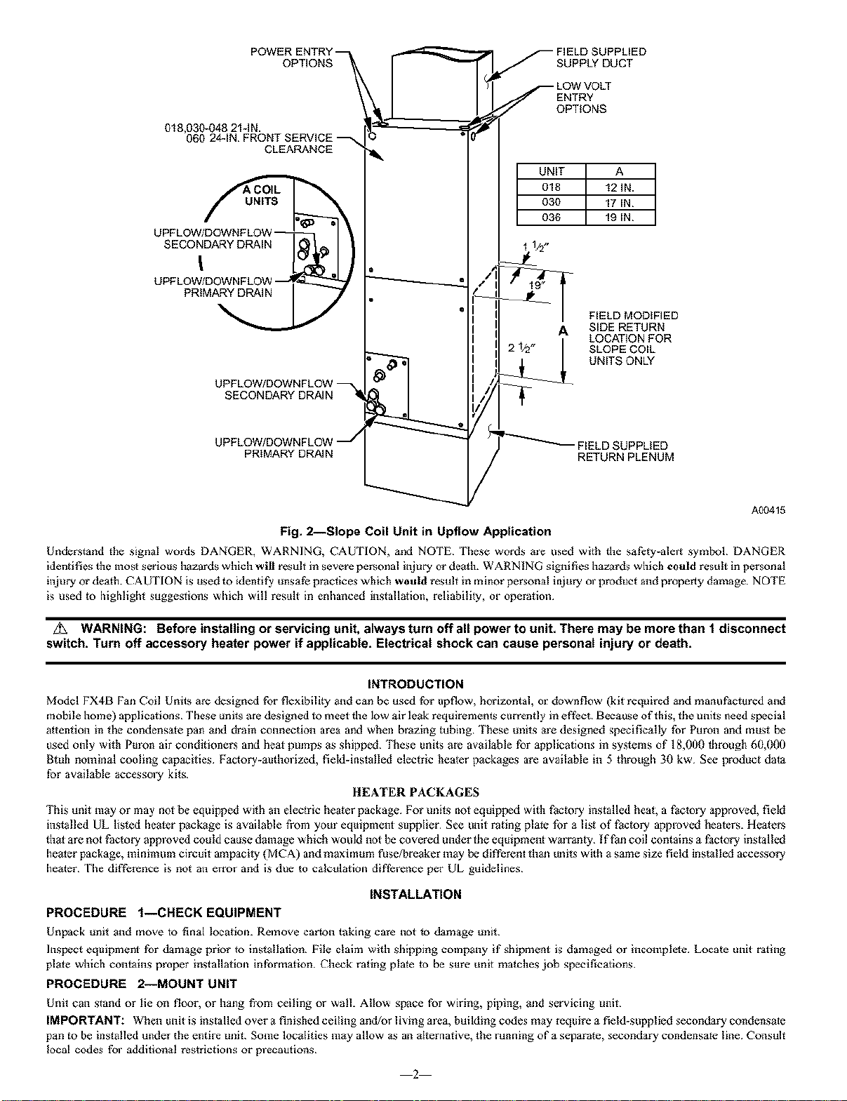
Fig. 2--Slope Coil Unit in Upflow Application
Understand the signal words DANGER, WARNING, CAUTION, and NOTE l'imse words me used with the safety-alm_ symbol DANGER
identifies the most serious hazards which will result in severe personal injury or dealh. WARNING sight fies hazards which could result in personal
m_ury or death. CAUTION is used m identify unsafe practices which would result in miner personal injury ol prcduct and properly damage NOTE
is used to highlight suggestions which will result in enhanced instafafon, reliabitgy, or opemfon
WARNING: Before installing or servicing unit, always turn off all power to unit. There may be more than t disconnect
switch. Turn off accessory heater power if applicable. Electrical shock can cause personal injury or death.
INTRODUCTION
Model FX4B Fan Coil Units are designed for flexibility and can be used for upfiow, horizontal, or down flow (kit required and manuPactured and
mobile home) applications These units are designed to meet the low air leak requirements currently in efi'eet Because of this, the units need special
attention in the condensate pan and drain connection area and when brazing tubing These tlnits ale designed specifically for Puron and must be
used only with Pmon air conditioners and heat pinups as shipped "l_ese units are available for applications in systems of 18,000 through 60,000
13tuh nominal cooling capacities Pactory-autholized, feId-instMled electric beater packages are available in 5 through 30 kw See prcduct data
for available accesso W kits
HEATER PACKAGES
I_ds unit may or may not be equipped with an electric heater package For ungs not equipped with l_ack_ry installed heah a factory approved, field
instadled UL listed heater package is available Prom yam equipment supplier See unit rating plate for a list of l_actory approved beaters. Healers
that are not Paetory approved could cause damage which would not be covered under the equipment wm_an_y/f l_n coil contains a factory installed
hemer package, minimum circuit ampac fly (MCA) andmaximum fuse/breaker may be different than units with a same size field installed accessory
healer fhe difference is not an er;or and is due to calculation difl'_rence per UL guidelines
INSTALLATION
PROCEDURE f--CHECK EQUIPMENT
Unpack t_ng and move to final location. Remove car[on laking care not to damage t_nit
Inspect equipment for damage prior to instaIlaflen File claim with shipping company if shipment is damaged or incomplete Locate unit raflng
plate which contains proper installation information Check rating plate to be sure unit matches job specifications
PROCEDURE 2--MOUNT UNIT
Unit can stand or lie on floor, or hang fiom ceiling or wall. Allow space for wiring, piping, and servicing mdt
IMPORTANT: When unit is installed over a finished ceiling and/or living mea, building cedes may require a field-supplied secondary condensate
pan _o be inslalled under the entire unik Some lecaliges may allow as an alternafve, file running of a separate, secondary condensate line Consult
local cedes fol additional restrictions or plecautions
2
Loading ...
Loading ...
Loading ...