Loading ...
Loading ...
Loading ...
_FAN DEC_
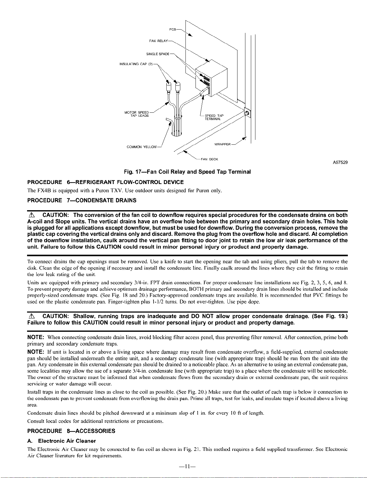
Fig. t7--Fan Coil Relay and Speed Tap Terminal
PROCEDURE 6--REFRIGERANT FLOW-CONTROL DEVICE
{]te FX4B is equipped with a Puron fXV Use outdoor units designed for Preen only.
PROCEDURE 7--CONDENSATE DRAINS
A97529
CAUTION: The conversion of the fan coil to downflow requires special procedures for the condensate drains on both
A-colt and Slope units. The vertical drains have an overflow hole between the primary and secondary drain holes. This hole
is plugged for all applications except downflow, but must be used for downflow. During the conversion process, remove the
plastic cap covering the vertical drains only and discard. Remove the plug from the overflow hote and discard. At completion
of the downflow installation, caulk around the vertical pan fitting to door joint to retain the low air leak performance of the
unit. Failure to follow this CAUTION coutd result in minor personal injury or product and property damage.
To connect draths the cap openings must be removed Use a knife to start the opening near the tab and using pliers, poll the tab lo remove the
disk. Clean the edge of the opening if necessary and instail the condensate tine Finally caulk around the lines where they exit the fitting to retain
the Iew leak rating of the mlit
Units are equipped with primary and secondary 3/4-in FPT drain connections¸ For proper condensale ithe instailations see Fig 2, 3, 5, 6, and 8
To prevent property damage and achieve opgnmm drainage performance, BOTH primary alld secondary drath gnes should be instaiIed arid include
properly-sized condensate traps¸ (See Fig. 18 and 20) Factory-approved condensate traps are avadabie, It is recommended tha_ PVC fittings be
used o11 the piastic condensate pan Finger_tigthen plus I_1/2 turns¸ Do no_ over_tigllten Use pipe dope¸
/_ CAUTION: Shallow, running traps are inadequate and DO NOT allow proper condensate drainage. (See Fig. t9.)
Failure to follow this CAUTION could result in minor personal injury or product and property damage.
NOTE: When connecting condensate dr_ain lines, avoid blocking filter access panel, thus preventing filler removal Afler connection, pdme both
primary and second_]y condensate h'aps.
NOTE: !f unit is located in or above a living sp_e where d_mage may result from condensate overflow, a field-supplied, external condensate
pan sbould be installed underneath the entire unit, and a secondary condensate line {with approprialc trap) should be run from the unit into the
pan Any condensate ill this external condensate pan sfiould be dl ained _o a noticeable place. As an alternative _o using an external COlldensate pan,
some localities may allow the use of ;1 separate 3/d-in condensalc line (with apprepriate trap) to a place where the condensate will be noticeable
{'he owner of the structure must be informed th_l witch condensate flows from the secondary dlain el external condensale pan, the unit requires
servicing or water d_mage will occur
Inst;dl traps in the condensate lines as close to the coil as possible (See Fig 20) Make sine that the outlet of e_h trap is below it connection to
the condensate p_n to prevent condensale from overgowing the dry,in pan Prime all traps, test fol leaks, _nd insulate traps if located above a living
area
C_ndensate dlain lines should be pitched downward at a minimum slop of 1 in for ever?, I0 fi of length
Consult local codes for eddifional restrictions or precautions.
PROCEDURE 8--ACCESSORIES
A. Electronic Air Cleaner
{]te Electronic Air Cleaner m_y be connected to Pan coil as shown in Pig. 21. {]tis method requires a field sopplied transformer See Electronic
Air Cleaner lileralure for kit requirements¸
il
Loading ...
Loading ...
Loading ...