Loading ...
Loading ...
Loading ...
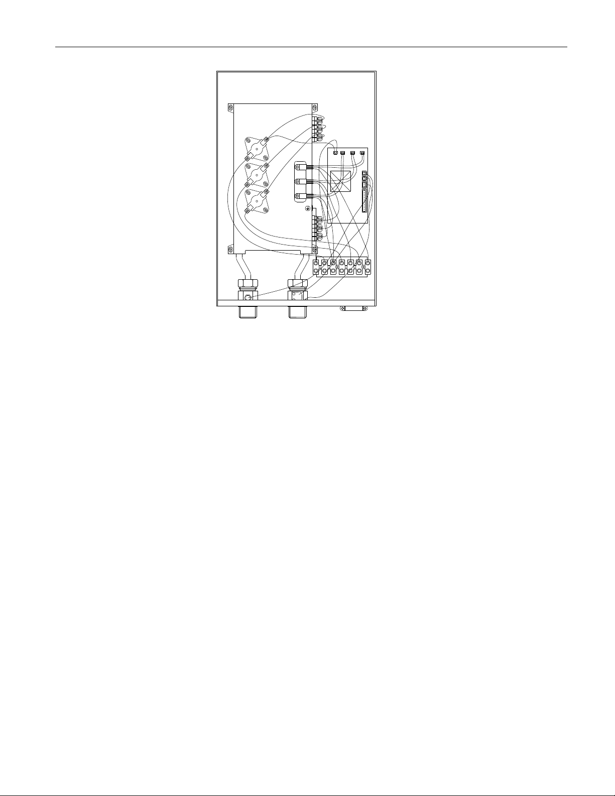
8
E L1 L2 L1 L2 L1 L2
6. PLUMBING AND MECHANICAL INSTALLATION
Please read these instructions truly and completely before installing your water heater.
Please follow all plumbing instructions carefully. This appliance must be installed by a licensed and qualified
plumber in accordance with all applicable national, state, provincial, and local plumbing codes. Failure to do so
could result in property damage and/or personal injury and void your warranty.
1. DO NOT SOLDER ANY PIPES WITH THE APPLIANCE CONNECTED TO. IF YOU DO, YOU COULD
DAMAGE THE FLOW SENSOR AND VOID THE WARRANTY.
2. A pressure valve and air purging fitting must be installed as shown in the cold water supply pipe, if the
pressure exceeds 150 psi (1 Mpa). Any threaded fittings should be installed using Teflon tape, or approved
liquid sealants, as code practices allow. The relief valve must be installed in accordance with applicable
codes. Use standard hydronic practices to eliminate air from the system.
3. Install air vent valves, expansion tanks, flow control valves, isolation valves, etc. as per code requirements.
4. The unit is designed to operate only when flow sensor senses water flow through it. Prior to powering up
(turning on your unit), PURGE ALL AIR FROM YOUR SYSTEM (see item 10 below), failure to do so might
cause an air-lock in your unit drying out the heat exchanger of your unit and cause permanent damage to the
heating element.
5. The unit should be connected directly to the water supply and it is extremely important to FLUSH the pipe
with water to remove any debris, or loose particles.
6. Check all the pipe connections and fittings for any leaks, and take corrective actions before proceeding.
7. Models MS120C2T_U require ½” NPT water connections.
8. Models MS150C2T_U, MS180C2T_U, MS210C2T_U, MS240C2T_U, MS270C2T_U require ¾” NPT water
connections.
9. Connect the cold water supply to the INLET threaded pipe, and the hot water to the OUTLET threaded pipe.
Important: A RUBBER WASHER MUST BE USED FOR PROPER SEAL.
Fig 8
Fix the appilance to the bracket which was screwed to the wall.
Make sure the unit is properly secured to the bracket.
Typical view (model MS210C2TMU)
Loading ...
Loading ...
Loading ...