
50Amp 125V/250V Shore Power Inlet / Installation Instructions
FURRION 50 ampères 125V/250V / Installation de votre fi che
WARNING
ELECTRICAL SHOCK
AND FIRE HAZARD!
To prevent the risk of electrocu-
tion or fi re, ensure the inlet and
connecting cables are NOT con-
nected to a power source during
installation! Use only 6 AWG or
above cable with this product.
Using a smaller AWG cable will
result in overheating and possible
Fire Hazard.
Cable color scheme for 125/250V 4
core cables:
Black = Y - Live/Hot Cable
Red = X - Live/Hot Cable
White = W - Neutral Cable
Green = G - Ground Cable (8 AWG)
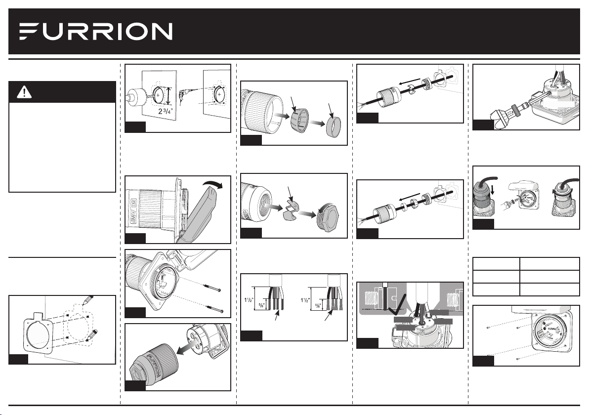
Installation
1. Select a suitable mounting position
for the power inlet. Mark a basic
outline for the inlet using the sup-
plied sealing gasket. (Fig. A)
Fig. A
2. Cut out the center circular hole
using a 2¾ ” hole saw and drill the
four mounting holes using a 1/8”
drill bit. (Fig. B)
Fig. B
3. Open the inlet cover and remove
the two screws holding the rear
housing. (Fig. C & Fig. D) Remove
the rear housing from the inlet.
(Fig. E)
Fig. C
Fig. D
Fig. E
4. Remove the strain relief insert
and the strain relief ring from the
inside of the rear housing. (Fig. F)
Fig. F
Strain Relief
Insert
Strain Relief
Ring
5. Rotate counterclockwise to remove
the strain relief nut and the cable
clip. (Fig. G)
Fig. G
Cable Clip
6. Strip off 1½” of the outer insula-
tion layer of the cable and 5/8” of
colored insulation from the ends of
the three conductor cables. (Fig. H)
Fig. H
Romex
Wire
Stranded
Core Wire
7. If you are using a Romex Wire,,
thread the cable through the sealing
gasket, strain relief nut, cable clip
and the rear housing. (Fig. I)
Fig. I
Required for Stranded Core Wire
only - If you are using a Stranded
Core Wire, thread the cable through
the sealing gasket, strain relief nut,
strain relief insert, strain relief ring
and the rear housing. (Fig. J)
Fig. J
8. Connect the colored wires to the
corresponding lettered holes on
the back of the inlet and tighten
the terminal screws to 22-25 in-lbs
torque. (Fig. K & Fig. L)
Black
Red
White
Red
White
Green
Black
Green
Fig. K
22-25 in-lbs
22-25 in-lbs
Fig. L
9. Replace the inlet rear housing and
secure with the two screws. Rotate
the rear cap clockwise to fi x the
cables. (Fig. M)
Fig. M
10. Fit the power inlet into the open-
ing and secure with four mounting
screws (not included). (Fig. N)
Housing Screw Size
Stainless KA3.5 x 30
Plastic PA3.5 x 30
Fig. N
Model: F52INS-SS/F52INS-PS/ F52INS-
GS/ F52INS-BS/ F52INR-PS/F52INS-BSN
IG-FET00008 V4.0
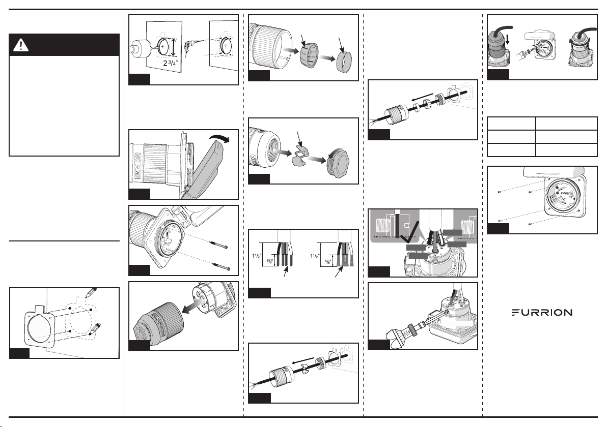
Installation
1. Sélectionnez une position de
montage appropriée pour la prise
d'alimentation. Marquer un con-
tour de base pour la prise à l'aide
de la rondelle fournie. (Fig. A)
Fig. A
2. Découpez le trou circulaire central
en utilisant une scie à trou 2¾ ",
percez les 4 trous de montage à
l'aide d'une mèche 1/8". (Fig. B)
Fig. B
3. Ouvrez le couvercle de la prise
et enlevez les 2 vis de fi xation du
boîtier arrière de la prise. (Fig. C &
Fig. D) Enlevez le boîtier arrière de
de la prise. (Fig. E)
Fig. C
Fig. D
Fig. E
4. Retirer l'insert de décharge de
contrainte et l'anneau de décharge
de contrainte de l'intérieur du
boîtier arrière. (Fig. F)
Fig. F
Insert de
décharge de
contrainte
Aanneau de
décharge de
contrainte
5. Tourner en sens inverse des
aiguilles d'une montre pour retirer
l' écrou de décharge de contrainte
et l'attache câble (Fig. G)
Fig. G
Attache câble
6. Dénuder 1½ "de la couche externe
d'isolation du câble et de 5/8"
d'isolant coloré à partir des ex-
trémités des trois fi ls conducteurs.
(Fig. H)
Fig. H
Fil de
Romex
Fil à noyau
tendu
7. Si vous utilisez un fi l Romex, en-
fi ler le câble à travers la rondelle
d'étanchéité, l' écrou de décharge
de contrainte, l'attache câble et le
boîtier arrière. (Fig. I)
Fig. I
Requis pour fi l à noyau torsadé
seulement - Si vous utilisez un fi l à
noyau torsadé, passez le câble à tra-
vers la rondelle d'étanchéité, l'écrou
de décharge de contrainte, l'insert de
décharge de contrainte, l'anneau de
décharge de contrainte et le boitier
arrière. (Fig. J)
Fig. J
8. Faites passer le câble à travers
la rondelle d'étanchéité et le
boîtier arrière de la prise. (Fig. F)
Connectez les fi ls colorés aux trous
correspondants marqués de lettres
sur le dos de la prise et serrez les
vis des bornes à une torque de 22-
25 in-lbs. (Fig. K & Fig. L)
Black
Red
Green
White
Fig. K
22-25 in-lbs
Fig. L
9. Remplacez le boîtier arrière de la
prise et le fi xez à l'aide de 2 vis.
Tournez le couvercle arrière dans
le sens des aiguilles d'une montre
pour fi xer les câbles. (Fig. M)
ATTENTION
RISQUES D’ELECTROCUTION ET
D’INCENDIES !
Afi n de prévenir tous risques
d’électrocution ou d’incendie, s’as-
surer que la fi che et les câbles de
connexion ne soient pas raccordés
au réseau pendant l’installation!
N’utiliser que du câble de type
AWG6 ou supérieur avec ce pro-
duit. Une section de câble trop fi ne
peut engendrer une surchauffe et
un risque d’incendie.
Le code couleur pour du câble 3
brins 125V est le suivant:
Noir (Y) = Y - tension réseau/service
Rouge (X) = X - tension réseau/
service
Blanc (W) = W - neutre
Vert (G) = G - masse (8 AWG)
Fig. M
10. Montez la prise d'alimentation
dans l'ouverture et le fi xer à l'aide
de 4 vis de fi xation (Non inclus)
(Fig. N)
Boîtier Taille de la vis
Inoxydable KA3.5 x 30
Plastique PA3.5 x 30
Fig. N
Furrion Innovation Center & Institute of
Technology
● 52567 Independence Ct., Elkhart, IN 46514, USA
● Toll free:1-888-354-5792
● Email: [email protected]
©2007-2018 Furrion Ltd. Furrion® and the Furrion logo
are trademarks licensed for use by Furrion Ltd. and
registered in the U.S. and other countries.
©2007-2018 Furrion Ltd. Furrion® et le logo Furrion
sont des marques déposées par Furrion Ltd. et enregis-
trées aux Etats-Unis et ailleurs.
FURRION.COM
Modèle: F52INS-SS/F52INS-PS/ F52INS-
GS/ F52INS-BS/ F52INR-PS/F52INS-BSN