Loading ...
Loading ...
Loading ...
TO INSTALL PLUNGE DEPTH KNOB
• Unplug the router.
• Remove upper hex nutfrom plunge depth shaft.
NOTE: This isthe only timeyou shouldremove the
hex nut from the muter. Also, ifyou removethe plunge
depth knob for any reason,you must reinstattthe hex
nut before reusingthe router.
• Turn remaining hex nut counterclockwiseuntil 1/4 in.
of thread is remainingat the top of the plunge depth
shalL
• Place compression springon top of bex nut.
• Place plungedepth knob on top of compressionspdng
and a|i0ntabs on knobwith flats on hex nut.
• Compress springby carefully pushingdown on top of
plunge depth knob,
• Thread plunge depth knobclockwise onto plunge
depth shaft.
WARNING: Replacing plunge depth knob without
compression sprtn0 could resultin plungedepth
knob and hex nut vibrating offplunge depth shaft.
This situationcoutd causemotor to separate from
router base, resultingin possibleseriouspersonal
injury,
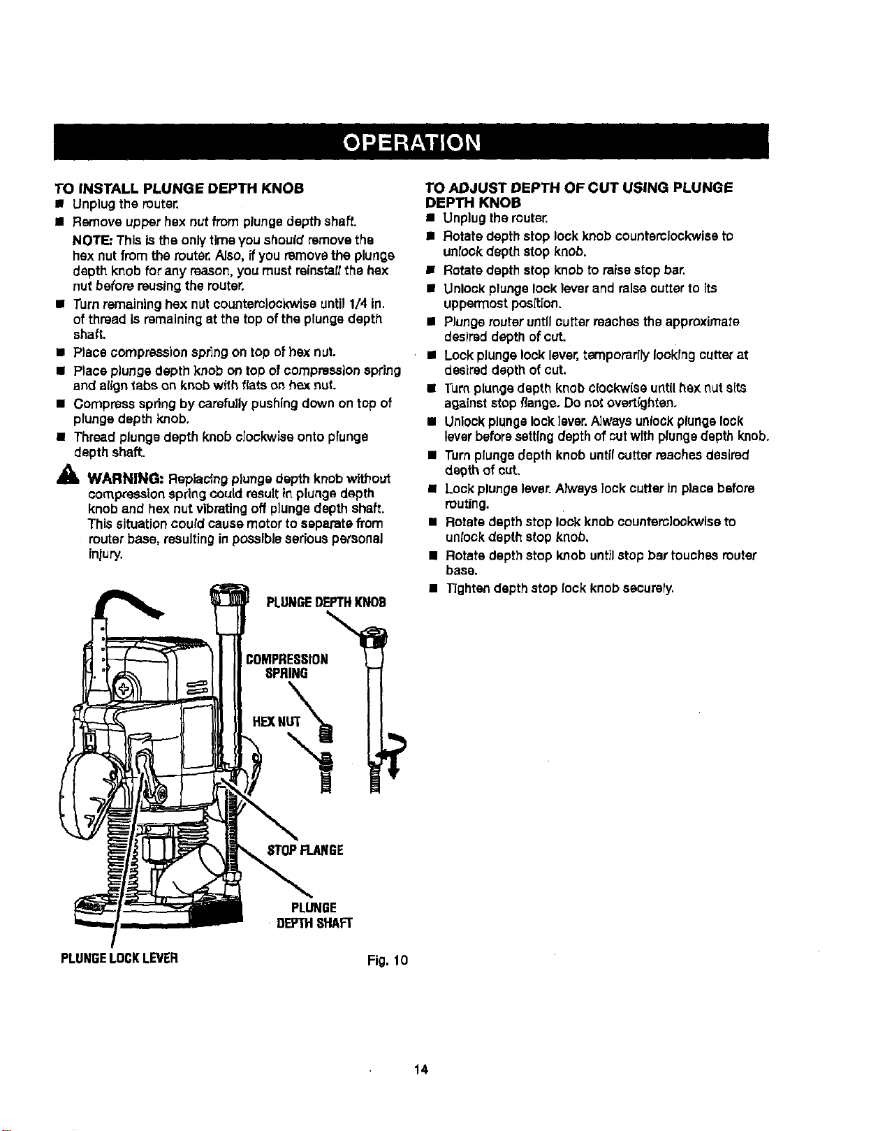
PLUNGEDEPTHKNOB
:OMPRESSION
SPRING
HEXN%_
TO ADJUST DEPTH OF CUT USING PLUNGE
DEPTH KNOB
• Unplug the router.
• Rotate depth stop lock knob counterclockwiseto
unlock depthstop knob.
• Rotate depth stop knobto raisestop bar.
• Unlock plungelooklever and raisecutter to {ts
uppermost posft[on.
• Plunge router untilcutter reaches theapproximate
desireddepth ofcut.
• Lock plungelock lever,ternporer[ry lookingcutter at
desired depth ofcut.
• Turn plungedepth knob c{ockw(seuntil box nuts(ts
againststop flange. Do not overtkJhten.
• Unlockplungelock lever.A]waysunlockplungelock
leverbeforesettingdepthof cutwith plungedepth knob.
• Turn plungedepth knob untilcutter reaches desired
decth of cut.
• Lock plungelever.Always lock cutter in place before
muting.
• Rotate depth stop lock knob counterclockwiseto
unlockdepth stop knob,
• Rotate depth stop knob untilstop bar touches router
base.
• Tightendepth stop lock knob securely.
STOPFLANGE
PLUNGE
DEPTHSHAFT
PLUNGELOCKLEVER
Fig. 10
14
Loading ...
Loading ...
Loading ...