Loading ...
Loading ...
Loading ...
MOUNTING THE MOTOR AND SWITCH
See Figures 24, 25, and 26.
• Locate the motor and switch assembly, the motor
mounting plate and the following hardware:
4 hex bolts (5/16-18 x 1 in.)
8 flat washers (5/16 in.)
4 lock washers (5/16 in.)
4 hex nuts (5/16-18)
2 hex bolts (5/16-18 x 3/4 in.)
2 screws (1/4-20 X 3/8 in.)
2 square nuts (1/4-20)
Yellow Switch key
Note: Remaining hardware from this bag is used for
installingthe belt guard.
• Release the bevel lock handle (front of the cabinet)
and turn the bevel handwheel (right side of the
cabinet) until the blade is fully vertical. Retighten
the bevel lock handle.
• Align the holes in the motor mounting plate and the
motor bracket so the top edges are even. Place a
flat washer on the four 1 in. bolts and insert them
into the holes.
• Install a flat washer, a lock washer, and a hex nut
on each bolt. Hand tighten only. This is the motor
support assembly.
• Center the motor side to side on the motor mount-
ing plate. Tighten the nuts with a 12 mm wrench.
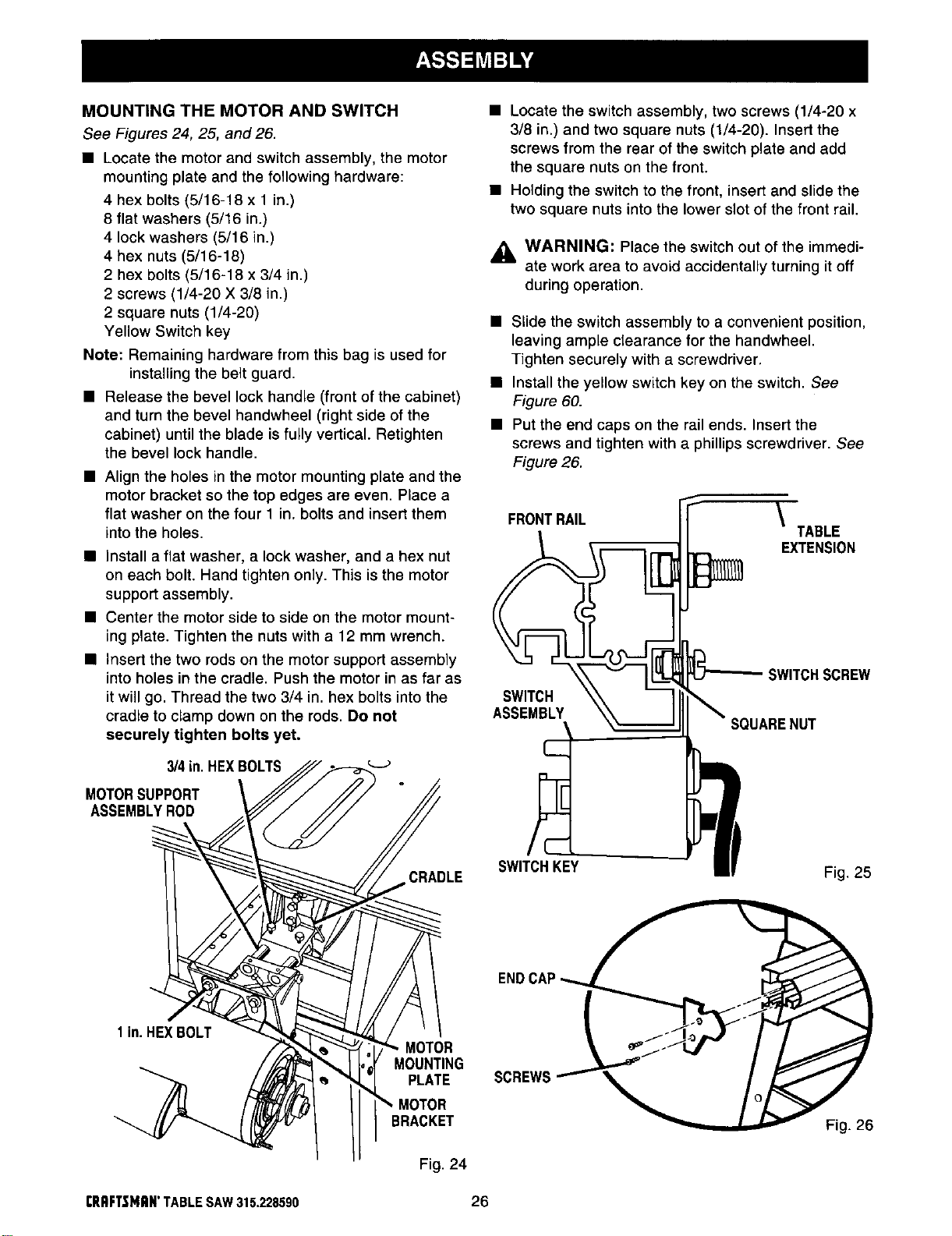
• Insert the two rods on the motor support assembly
into holes in the cradle. Push the motor in as far as
itwill go. Thread the two 3/4 in. hex bolts intothe
cradle to clamp down on the rods. Do not
securely tighten bolts yet.
3/4in.HEXBOLTS
MOTORSUPPORT
ASSEMBLYROD
CRADLE
• Locate the switch assembly, two screws (1/4-20 x
3/8 in.) and two square nuts (1/4-20). Insert the
screws from the rear of the switch plate and add
the square nuts on the front.
• Holding the switch to the front, insert and slide the
two square nuts into the lower slot of the front rail.
_1= WARNING: Place the switch out of the immedi-
ate work area to avoid accidentally turning it off
during operation.
• Slide the switch assembly to a convenient position,
leaving ample clearance for the handwheel.
Tighten securely with a screwdriver.
• Install the yellow switch key on the switch. See
Figure 60.
• Put the end caps on the rail ends. Insert the
screws and tighten with a phillips screwdriver. See
Figure 26.
FRONTRAIL
\
TABLE
EXTENSION
SWITCHSCREW
SWITCH
ASSEMBLY
UARENUT
SWITCHKEY
Fig. 25
lin. HEXBOLT
MOTOR
MOUNTING
PLATE
SCREW_
BRACKET
Fig. 24
Fig. 26
rlIRFT$1411N'TABLESAW315.228590 26
Loading ...
Loading ...
Loading ...