
PRODUCT
MANUAL
UWM-2
WIRELESS
LAVALIER
MICROPHONE
DUAL CHANNEL UHF
TR AN SM IT TE R
TR AN S MI TT ER
RE C EI VE R

2
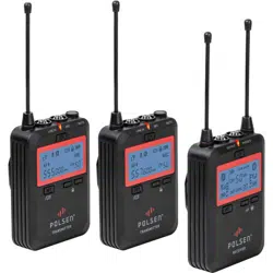
THANK YOU FOR CHOOSING POLSEN.
The Polsen UWM-2 is a camera mountable 100-channel UHF wireless system that can transmit audio up to
300 feet. This wireless mic system is engineered with professional features like headphone monitoring, line
input, and frequency agility, which make it ideal for video applications such as interviews, lectures, dialog,
and conferences. You can choose from 100 channels to avoid interference. Up to four UWM-2 systems can be
deployed simultaneously in the same location. Whether you’re using a camcorder, DSLR camera, or portable
recorder, you’ll capture pristine and broadcast-quality audio.
The receiver features a line output and included 2-channel XLR cable for professional cameras. It also includes
a cable for recording your audio to a DSLR, consumer camcorder, or smartphone that has a 1/8 in. (3.5 mm)
mic input. The system’s transmitter features a gain control that ensures an optimum signal level for the
receiver. It’s also equipped with a line input that enables the transmission of such devices as an audio mixer,
smartphone, or portable recorder.
This wireless microphone system operates in the UHF 500 MHz bandwidth, assuring less susceptibility to
interference than VHF systems and greater reliability at longer distances. Operating in this bandwidth also
ensures that the UWM-2 system is future proof and meets current and known future FCC regulations.

3
PRECAUTIONS
• Exposure to high sound levels can cause permanent hearing loss. Avoid listening at high volumes for
extended periods of time.
• Keep this unit away from water and any ammable gases or liquids.
• Handle this product with care.
• Clean this product with only a soft, dry cloth.
• Keep this product away from children.
• Use only parts provided by the manufacturer.
• All images are for illustrative purposes only.
4
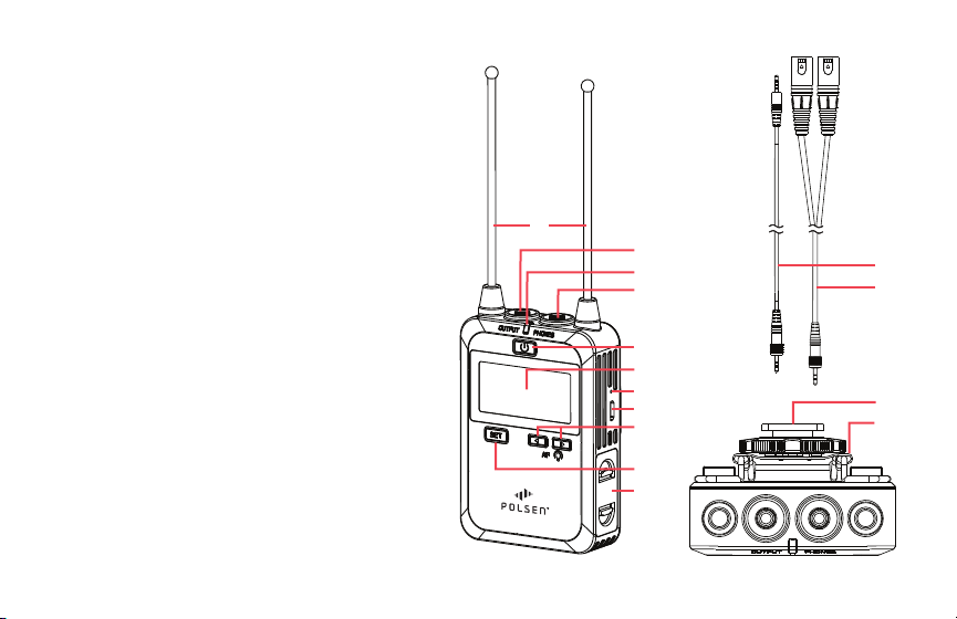
RECEIVER
1. Antennas
2. Audio output
3. Power indicator
4. Headphone output
5. Power button
6. LCD screen
7. Charging status indicator
8. USB Micro-B charging port
9. Left and right buttons
10. Set button
11. Battery compartment
12. 1/8 in. (3.5 mm) TRS to TRRS cable
13. 1/8 in. (3.5 mm) TRS to dual XLR cable
14. Shoe-mount adapter with 1/4-20 socket
15. Belt clip
R EC E IV ER
2.
1.
3.
4.
5.
6.
7.
8.
10.
11.
9.
12.
13.
14.
15.
5
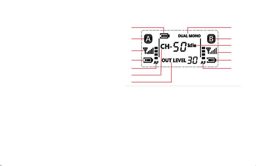
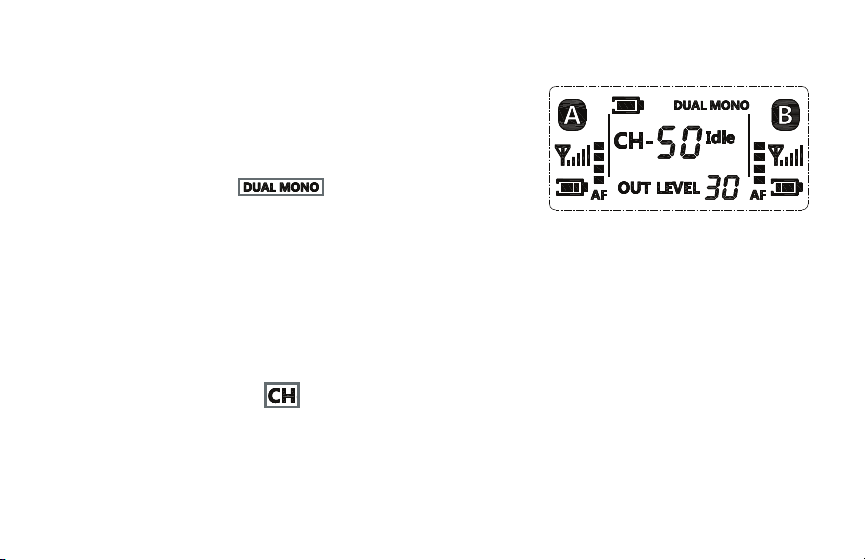
LCD SCREEN RECEIVER
1. Battery indicator
2. Transmitter status indicator (Channel A)
3. RF reception indicator (Transmitter A)
4. Battery status (Transmitter A)
5. Audio level meter (Transmitter A)
6. Channel indicator
7. Output level indicator
8. Audio output mode indicator
9. Transmitter status indicator (Channel B)
10. Channel status indicator
11. RF reception indicator (Transmitter B)
12. Battery status (Transmitter B)
13. Audio level meter (Transmitter B)
1.
2.
3.
4.
5.
6.
7.
8.
9.
11.
12.
13.
10.
6
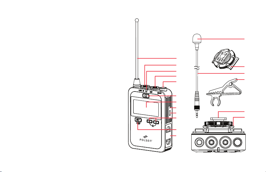
TRANSMITTER
1. Antenna
2. Line level input
3. Power indicator
4. Mic level input
5. Mute button
6. Power button
7. LCD screen
8. Charging status indicator
9. USB Micro-B charging port
10. Left and right buttons
11. Set button
12. Battery compartment
13. Foam windscreen (×2)
14. Shoe-mount adapter with 1/4-20 socket
15. Omnidirectional lavalier microphone (×2)
TR A NS M IT TE R
2.
1.
3.
4.
6.
7.
8.
9.
11.
12.
10.
5.
17.
18.
16.
15.
14.
16. Tie clip (×2)
17. Shoe mount
18. Belt clip
13.
7
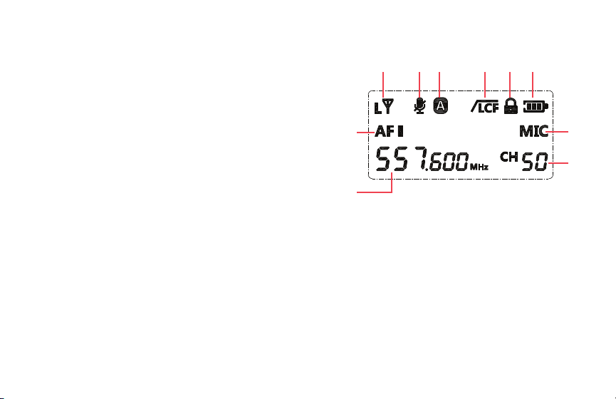
LCD SCREEN TRANSMITTER
1. RF transmission power indicator
2. Mute indicator
3. Transmitter channel selector
4. Low-cut lter
5. Function lock
6. Battery indicator
7. Mic / Line indicator
8. Frequency channel selector / Input level (Gain)
9. Frequency indicator
10. Level meter
1.
7.
2. 3. 4. 5. 6.
8.
10.
9.

8
INSTALLING THE BATTERIES
Transmitter and Receiver
The transmitter and receiver are each powered by two AA batteries. To install the batteries, follow these steps.
1. Make sure the units are turned off by pressing and holding the power button on all units.
2. Pinch the battery compartment tabs together, and the compartment door will pop open.
3. Insert fresh batteries, following the orientation diagram on the back of the unit.
4. Press the compartment door down over the batteries until it locks into place.
Rechargeable Batteries
You can use rechargeable AA batteries with the receiver and transmitter.
To recharge: Place them in the battery compartment and connect the receiver or transmitter to a powered USB
port or charging device with a Micro-USB to USB Standard-A cable (not included).
Charging status indicator:
RED Charging in progress
GREEN Charging complete
Important! Do not attempt to recharge non-rechargeable batteries—this may result in damage to the unit and
void the warranty.

9
Tip: Before you record, insert fresh batteries into the transmitter and receiver. Have spare fresh batteries on hand
during a session. If you’re using rechargeable batteries, bring extra batteries and a battery charger with you.
MOUNTING
The transmitter and receiver can be worn attached to a belt or mounted on a camera, or attached to a tripod or
articulating arm.
Belt Clip
Attach the included belt clip by pinching the two ends together and inserting them
into the holes on the back of the unit.
Shoe Mount
The transmitter and receiver can be attached to your camera with the shoe-mount
adapter. You can also move the unit off your camera by attaching it to the shoe
mount that’s built into many ring lights, LEDs, and articulating arms.
1. Attach the shoe-mount adapter by tting the two hooks over each side of the
belt clip’s center section.
2. Loosen the shoe-mount adapter’s locking wheel by turning it clockwise, and slide
it into the shoe mount. Make sure it’s fully inserted, then turn the locking wheel
counterclockwise to tighten until it’s secure.

10
Tripod Mounting
If you prefer a secure stationary place for the transmitter or receiver, mount it to an accessory with a 1/4-20
mounting screw like a tripod or light stand.
1. Follow the instructions above for attaching the shoe-mount adapter.
2. Use the 1/4-20 socket on the shoe-mount adapter to screw the unit onto a tripod or light stand that has a
1/4-20 mounting screw.
BEFORE YOU BEGIN
The UWM-2 Dual Channel Wireless System is intuitive and easy to operate.
If you choose to begin using the system before reading the operating instructions, follow these operating tips:
Channel Selection
The transmitters and the receiver must all be set to the same channel number whether the transmitters are set to
transmitter channel A or B.
See
Setting the Receiver Channel
and
Setting the Transmitter Channel
below.
Locking Connectors
To ensure the cables are not disconnected from the UWM-2 during a recording or performance, the included cables
have locking 1/8 in. (3.5 mm) connectors.
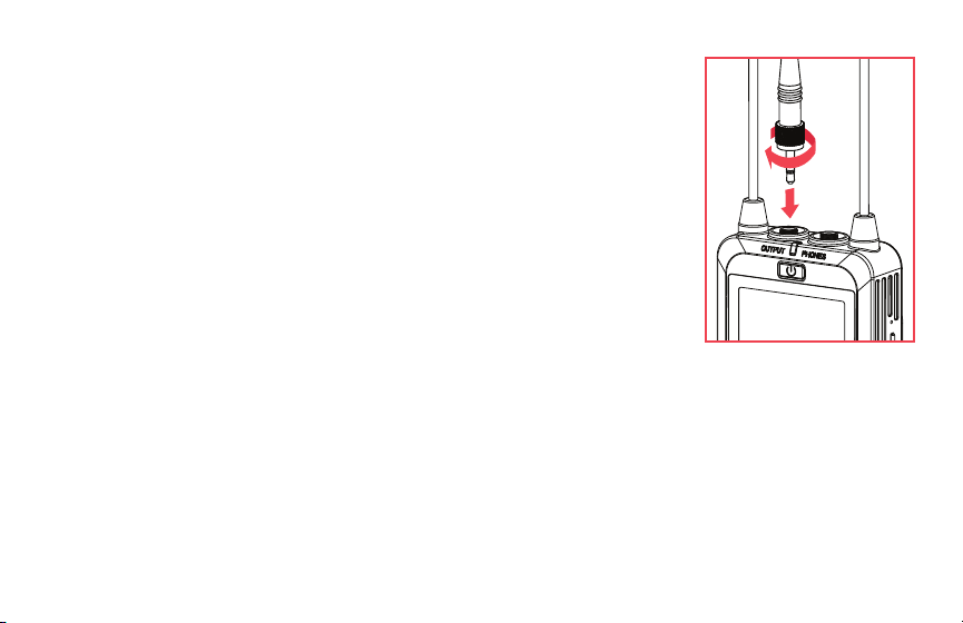
11
Make sure to attach the plug with the locking connector to the transmitter and
receiver.
Fully insert the plug into the jack, and turn the locking collar clockwise until secure.
Don’t overtighten the locking connection.
OPERATING RANGE
Each transmitter has a normal operating range of 150 ft. (45.7 m), and 300 ft. (91.4 m)
in optimum conditions.
An intermittent or weak signal can be an indication that you have reached the
maximum operating distance. The operating range can change depending factors
such as weather, atmospheric conditions, terrain, obstructions, and battery power.
If you notice signal intermittence, dropouts, or decreased volume.
1. Move the transmitters closer to the receiver.
2. Eliminate obstructions to the line of sight between transmitters and receiver.
3. Check the battery power in the transmitters and receiver. If the battery power is low, replace or fully recharge
the batteries.

12
INTERFERENCE
Radio Frequency (RF) or Electromagnetic (EM) interference can cause buzzing or humming, noise bursts, pops,
clicks, and dropouts.
The channel status indicator shows whether a channel is usable, or if it has interference that can affect your audio.
See
Finding an Interference-Free Channel
below.
If the channel status indicator shows channel interference, or if interference develops while the system is in use,
change the transmitters and receiver channel:
Important! The transmitters and the receiver must all be set to the same channel.
To avoid interference:
1. Turn off smartphones, walkie talkies, and computers in the area.
2. Try to avoid areas where there are high-voltage power cables for lighting and sound equipment.
3. Improve the line of sight between the transmitters and the receiver.
4. If the receiver is inside a metal equipment rack, move it a location where it isn’t surrounded by metal.
Play/pause, volume control, and forward and back track selection can be controlled from the front panel or from
the remote.

13
CONNECTING THE RECEIVER
1/8 in. (3.5 mm) TRS to Dual XLR Cable
Use this cable to connect the two-channel output of the receiver to a camcorder, portable recorder/mixer, or
mixing board.
1/8 in. (3.5 mm) TRS to TRRS
Plug the TRS plug with the locking connector into the receiver’s output, and connect the TRRS plug to the audio
input of a smartphone, DSLR camera, or computer.
Headphones
To monitor the audio in real time, plug a headphone with a 3.5 mm connector into the headphone jack.
CONNECTING THE TRANSMITTER
Lavalier Microphone
Plug the included lavalier microphone into the mic input to broadcast the voice to the receiver.
Line Level Audio Source
Transmit the audio from a device like a smartphone, portable recorder, or computer to the receiver by connecting
the output of the device to the 1/8 in. (3.5 mm) line in plug.
14
OPERATING THE RECEIVER
Powering On
Press and hold the power button until the screen illuminates.
The battery indicator shows the remaining battery power.
Setting the Output Signal
The receiver can output a mixed stereo signal or a dual mono signal.
• Select the mixed stereo signal when there is only one XLR input available on your camera for your audio.
• The dual mono signal is good for recording dialog, so each signal is routed to its own channel.
To set the output signal:
1. Press the set button repeatedly until the audio output mode indicator blinks.
2. Use the left or right button to select mix or dual mono, and press the set button.
Setting the Receiver Channel
1. Press the set button repeatedly until the channel icon blinks.
2. Use the left/right buttons to select a channel.
3. Press the set button to set the selection.

15
Important: Both transmitters and the receiver must be set to the same channel. See
Setting the Transmitter Channel
below.
Finding an Interference-Free Channel
The channel status indicator shows whether a channel is usable, or if it has excessive interference that will affect
your audio.
Busy indicates the receiver has detected interference on the channel. Select another channel.
Idle indicates there is no interference on that channel.
Adjusting the Output Level
Refer to the documentation that came with your recorder, camera, or camcorder for its optimum input signal level.
The receiver's default output level is 27.
To adjust the receiver’s output level:
1. Press the set button repeatedly until the output level indicator blinks.
2. Use the left/right buttons to raise or lower the level.
Selecting a Transmitter Signal
The receiver gives you the option of either recording both channels simultaneously, or just one channel if you’re
recording solo talent.

16
When the receiver is not connected to the transmitter, the transmitter signal indicator will blink. A steady
transmitter indicator means the receiver is connected and receiving signal from the transmitter.
To select a transmitter signal:
1. Press the set button repeatedly until one or both transmitter indicators blink.
2. Use the left/right buttons to select transmitter A, B, or both.
3. Press the set button.
Important: Each transmitter signal must be set to the same channel as the receiver. See
Setting the Receiver
Channel
above, and
Setting the Transmitter Channel
below.
Signal Strength
The RF reception indicator shows the strength of the transmitter’s signal to the receiver.
Ideally, the reception should be at full strength. To remedy a weak signal, see
Setting Signal Strength
below.
Audio Level
Each transmitter signal has an audio meter. The level of the transmitter signal should be strong enough to record
audio accurately and without distortion or dropouts.
17
The audio level should be as high as possible without peaking. If the meter rises to the top due to intermittent
loud noises or vocal plosives like P and B sounds, it could distort the audio. To remedy peaking audio, see
Setting Mic/Line Level Input
and
Setting Input Volume (Gain)
below.
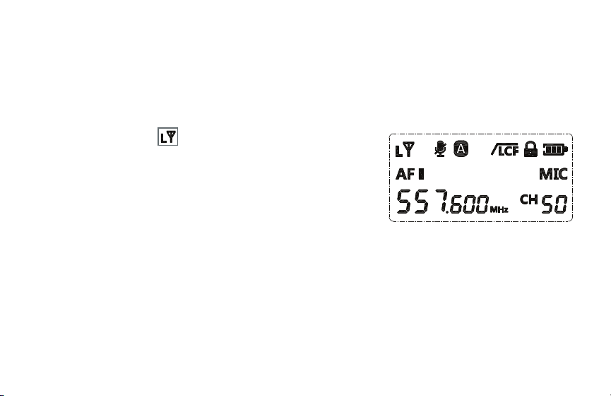
OPERATING THE TRANSMITTER
Setting Signal Strength
The transmitter has a selectable high and low RF transmission power
setting.
L (Low, 15 mW) is ideal when the transmitter is close to the receiver.
It also provides the transmitter with approximately 20% more run time.
H (High, 25 mW) transmits a stronger signal, and allows the microphone
to cover a wider area and more range. This setting is recommended if your subject is moving around or is
consistently more than 200 feet from the receiver. This setting is also recommended if you’re recording in an area
with heavy RF interference.

18
To set the signal strength, follow these steps:
1. Press the set button repeatedly until the RF transmission power indicator blinks.
2. Use the left/right buttons to select H (high) or L (low).
3. Press the set button to accept.
Setting the Transmitter Channel
The transmission channel determines whether the transmitter sends the signal to the receiver on channel A or B.
To set the transmitter channel:
1. Press the set button repeatedly until the transmitter channel selector blinks.
2. Use the left/right buttons to select transmitter channel A or B.
3. Press the set button or wait for 10 seconds to implement the change.
Once the transmitter channel is selected, the transmitter channel status indicator will appear steadily on the
receiver to indicate that signal is being received. If the receiver’s transmitter channel indicator blinks, no signal is
being received on that channel.

19
Setting Mic/Line Level Input
Select mic to use the included lavalier microphone.
Select line to transmit the signal from a smartphone, computer, portable recorder, or eld mixer.
To set the input level:
1. Press the set button repeatedly until the mic/line indicator blinks.
2. Use the left/right buttons to select mic or line.
3. Press the set button or wait for 10 seconds to implement the change.
Setting a Frequency Channel
Setting the channel selects the frequency used to transmit the signal to the receiver. There are 50 frequencies to
choose from on each A and B transmitter channels.
Select an interference-free channel on the receiver rst. Then set the transmitter to the same channel.
1. Press the set button repeatedly until the channel indicator blinks.
2. Use the left/right buttons to select a channel that matches the receiver’s channel.
3. Press the set button or wait for 10 seconds to accept the change.

20
Setting Input Volume (Gain)
VOL
The transmitter’s input volume level, or gain, determines the signal level that’s sent to the receiver.
For optimum recording levels, see
Audio Level
above.
To set the input volume:
1. Press the set button repeatedly until the volume level indicator blinks.
2. Use the left/right buttons to adjust the volume from 0 to 7.
Important! Setting the volume to 0 means no sound is transmitted to the receiver.
3. Press the set button or wait for 10 seconds to accept.
Low-Cut Filter
Activate the low-cut lter to minimize low-frequency noise like rumble, room noise, or noise from fans, air
conditioners, and overhead uorescent lights.
To activate the low-cut lter, press and hold the set button until the LCF icon appears on the screen.
To turn off the low-cut lter, press and hold the set button until the LCF icon turns off.

21
Muting the Transmitter
The mute button mutes the input signal to the transmitter.
Press the mute button to mute the microphone while another person is speaking, or to prevent the microphone
from picking up a separate audio source like programmed music or a video presentation.
Locking the Transmitter
Activating the transmitter lock prevents accidental changes to the transmitter’s settings while a recording is in
progress.
Press the left and right buttons simultaneously, and the lock icon appears on the screen.
Press the left and right buttons simultaneously again to unlock the transmitter.
STAGE DIRECTION AND TALENT CUEING
The UWM-2 can be used as an impromptu one-way voice communication system for stage directions and talent
cueing. In this case, your talent will operate the receiver instead of the transmitter, and monitor via an earphone
(not included) plugged into the headphone output. The offstage instructor can relay directions into the microphone
via the transmitter from a remote location, or send cues from a broadcast mixer or IFB system via the line input on
the transmitter.

22
SYSTEM
WIRELESS TRANSMISSION
Analog UHF
OPERATING RANGE
150 ft. (39.6 m)
300 ft. (91.4 m) in optimum conditions
FREQUENCY RANGE 538.000 to 586.000 MHz
INCLUDED TRANSMITTERS
2 × bodypack with lavalier microphone
NUMBER OF RF CHANNELS 100 (50 per transmitter channel)
DIVERSITY No
RF FREQUENCY BAND
A: 538.000 to 557.600 MHz
B: 556.400 to 586.000 MHz
RF BANDWIDTH 48 MHz
FREQUENCY STEP SIZE 400 KHz
TOTAL HARMONIC
DISTORTION
<0.8%
MAX OPERATING RANGE
>100 ft. (30.5 m); 300 ft. (91.4 m) in optimum conditions
MODULATION Wide band FM
SPECIFICATIONS

23
TRANSMITTER
FORM FACTOR
Body pack
RF POWER OUTPUT
15 mW, 25 mW
AUDIO I/O 1/8 in. (3.5 mm) female line in (lockable)
1/8 in. (3.5 mm) female mic in (lockable)
THD 0.5% or less (-60 dBV, 1 kHz input)
SIGNAL-TO-NOISE RATIO ≥70 dB
MUTING Yes, mute switch
AUDIO INPUT LEVEL -60 dBV
GAIN RANGE 22 dB
FREQUENCY RESPONSE 20 Hz to 18 kHz
SYNC METHOD Manual
ANTENNA 1 exible, xed
RF OUTPUT POWER
Low: 15 mW
High: 25 mW
POWER REQUIREMENTS
AA battery (×2)

24
TRANSMITTER CONT.
APPROXIMATE BATTERY LIFE 8 hours (alkaline)
DISPLAY & INDICATORS Backlit LCD (transmitter signal strength, transmission channel, mic/line, channel,
volume, low-cut lter, mute)
OPERATING TEMPERATURE
32°F to 122°F (0°C to 50°C)
DIMENSIONS H × W × D 3.5 × 2.4 × 0.9 in. (8.9 × 6.2 × 2.2 cm)
WEIGHT 2.8 oz. (80 g)

25
RECEIVER
FORM FACTOR Camera mount
MOUNTING OPTIONS Mounting foot, 1/4-20 threaded socket, belt clip
ANTENNA 2 exible, xed
NUMBER OF AUDIO CHANNELS 2 (mixed, dual mono)
AUDIO I/O 1/8 in. (3.5 mm) female lockable
1/8 in. (3.5 mm) headphone out
DYNAMIC RANGE
40 Hz to 18 kHz (± 3 dB)
SIGNAL-TO-NOISE RATIO
<70 dB
POWER REQUIREMENTS
AA battery (×2)
OPERATING TIME Approximately 8 hours (alkaline)
DISPLAY & INDICATORS Backlit LCD (transmission channel, dual mono/stereo, channel, output level, RF signal,
audio level meter, battery status)
HOUSING ABS Plastic
OPERATING TEMPERATURE
32°F to 122°F (0°C to 50°C)
DIMENSIONS H × W × D 3.5 × 2.4 × 0.9 in. (8.9 × 6.2 × 2.2 cm)
WEIGHT 2.6 oz. (75 g)

26
MICROPHONE
TRANSDUCER Back electret condenser
POLAR PATTERN Omnidirectional
FREQUENCY RESPONSE 50 Hz to 20 kHz
SENSITIVITY
-37 dB ±
IMPEDANCE 2.2 kΩ
MAXIMUM SPL 100 dB
TOTAL HARMONIC DISTORTION
<5%
OPERATING VOLTAGE 1 to 5 V
HEAD DIAMETER 0.25 in. (0.6cm)

27
FREQUENCY ALLOCATION CHART
TRANSMITTER A TRANSMITTER B
CHANNEL FREQUENCY FREQUENCY
1 538.000 566.400
2 538.400 566.800
3 538.800 567.200
4 539.200 567.600
5 539.600 568.000
6 540.000
568.400
7 540.400 568.800
8 540.800 569.200
9 541.200 569.600
10 541.600 570.000
11 542.000 570.400
12 542.400 570.800
13 542.800 571.200
14 543.200 571.600
TRANSMITTER A TRANSMITTER B
CHANNEL FREQUENCY FREQUENCY
15 543.600 572.000
16 544.000 572.400
17 544.400 572.800
18 544.800 573.200
19 545.200 573.600
20 545.600
574.000
21 546.000 574.400
22 546.400 574.800
23 546.800 575.200
24 547.200 575.600
25 547.600 576.000
26 548.000 576.400
27 548.400 576.800
28 548.800 577.200

28
TRANSMITTER A
CONT.
TRANSMITTER B
CONT.
CHANNEL FREQUENCY FREQUENCY
29 549.200 577.600
30 549.600 578.000
31 550.000 578.400
32 550.400 578.800
33 550.800 579.200
34 551.200 579.600
35 551.600 580.000
36 552.000 580.400
37 552.400 580.800
38 552.800 581.200
39 553.200 581.600
40 553.600 582.000
41 554.000 582.400
42 554.400 582.800
TRANSMITTER A
CONT.
TRANSMITTER B
CONT.
CHANNEL FREQUENCY FREQUENCY
43 554.800 583.200
44 555.200 583.600
45 555.600 584.000
46 556.000 584.400
47 556.400 584.800
48 556.800 585.200
49 557.200 585.600
50 557.600 586.000

29
Problem Solution
The audio is noisy or
distorted. This can
include dropouts,
white noise, bursts,
pops, and clicks.
• Noise might be caused by RF interference. Try a different channel. Make sure both units are on the same
channel.
• There can be a lot of RF interference outdoors. Try moving indoors, where there is less RF interference.
• Keep the units’ antennas at least 2 feet (0.6 m) away from conductive objects like metal and water.
Overhead telephone lines, fluorescent lighting, and metal fences can all cause interference.
• Turn off all nearby computers and mobile phones.
• Test your RF environment before recording. To do this, turn on the receiver. If there is noise from interference
on the channel, the channel indicator will show BUSY, and you should avoid using it.
• Noise can also be caused by receiver overload. If the antennas are too close, it can cause receiver overload
(intermodulation). Make sure the antennas are at least 3 feet (0.9 m) away from each other.
• You may be experiencing a weak signal. Make sure there is an unobstructed line of sight between the
receiver’s and the transmitter’s antennas. Keep in mind that your body, wardrobe, and onstage sets are
possible obstructions. Make sure the receiver and transmitter are within the 300-foot (100 m) range. If
there are obstructions, you may need to move closer.
The receiver is
getting sound from
only one channel.
• Set both transmitters and the receiver to the same channel.
• Set the transmitter volume to a higher output level.
• Make sure the transmitter is within range of the receivers.
• Make sure one transmitter is set to transmitter channel A, and the other is set to transmitter channel B.
TROUBLESHOOTING

30
Problem Solution
The input level on
the camera, recorder,
or mixer is too high.
• Turn down the audio input level on your camera or recording device.
• Decrease the receiver’s output level.
• Make sure the output of the receiver is plugged into the line-level input on your mixer, or that the line/mic
switch on your mixer is set to line.
• Turn down the gain on your mixer.
• Adjust the output volume on the transmitter, but keep this level as high as possible without distortion.
There is no audio.
• Make sure the transmitter’s mute button is not active.
• Check all cables to make sure they are completely plugged into the proper inputs.
• If you are transmitting a line-level signal, make sure there is audio coming out of the line-source device.
• If you want to record via the microphone input, make sure there is nothing plugged into the transmitter’s
line-level input.
• If there is no sound in the headphones, make sure the headphones are completely plugged into the
headphone jack. Increase the receiver’s output level.
• Make sure the transmitter and receiver are set to the same channel.
• Make sure the receiver is receiving signal from the transmitters, and the transmitter indicators are not
blinking.

31
Problem Solution
Too much ambience
is being picked up.
• If you’re using an omnidirectional microphone, the microphone may be picking up too much ambience or
room noise.
• Make sure the microphone is as close as possible to the subject. Approximately 6 inches (15.2 cm) from the
subject is usually good microphone placement, but you may need to experiment.
• Reduce acoustic reflections in the area by hanging an acoustic blanket, acoustic foam, fabric, or rug over
bare walls, floors, and windows.
Too much low-
frequency noise and
rumble are being
picked up.
• Activate the low-cut filter on the transmitter.
• Make sure the foam windscreen is on the lavalier microphone to minimize wind noise.
• Turn off nearby fans or air conditioning units.

32
ONE-YEAR LIMITED WARRANTY
This Polsen product is warranted to the original purchaser to be free from defects in materials and workmanship under normal consumer
use for a period of one (1) year from the original purchase date or thirty (30) days after replacement, whichever occurs later. The warranty
provider’s responsibility with respect to this limited warranty shall be limited solely to repair or replacement, at the provider’s discretion,
of any product that fails during normal use of this product in its intended manner and in its intended environment. Inoperability of the
product or part(s) shall be determined by the warranty provider. If the product has been discontinued, the warranty provider reserves the
right to replace it with a model of equivalent quality and function.
This warranty does not cover damage or defect caused by misuse, neglect, accident, alteration, abuse, improper installation or
maintenance. EXCEPT AS PROVIDED HEREIN, THE WARRANTY PROVIDER MAKES NEITHER ANY EXPRESS WARRANTIES NOR ANY IMPLIED
WARRANTIES, INCLUDING BUT NOT LIMITED TO ANY IMPLIED WARRANTY OF MERCHANTABILITY OR FITNESS FOR A PARTICULAR
PURPOSE. This warranty provides you with specic legal rights, and you may also have additional rights that vary from state to state.
To obtain warranty coverage, contact the Polsen Customer Service Department to obtain a return merchandise authorization (“RMA”)
number, and return the defective product to Polsen along with the RMA number and proof of purchase. Shipment of the defective product
is at the purchaser’s own risk and expense.
For more information or to arrange service, visit www.polsenaudio.com or call Customer Service at 212-594-2353.
Product warranty provided by the Gradus Group.
www.gradusgroup.com
Polsen is a registered trademark of the Gradus Group. © 2020 Gradus Group LLC. All Rights Reserved.
GG1
