SECURE I SECURE PLUS I SECURE PRO
INSTALLATION MANUAL
DEADBOLT EDITION
SECURE
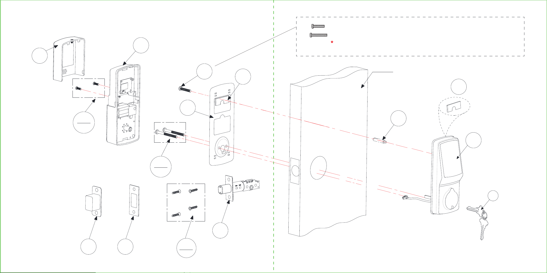
INSTALLATION OVERVIEW & PARTS LIST
Lockly Secure can be fitted for both right swing doors and left swing doors.
I
K
2X
H
F
D
J
L
N
4X
Battery Cover
Interior Assembly
PM5 Screw
Mounting
Plate
Adhesive
Deadbolt
Strike Plate
Dust Box
KA4*20MM Screw
PM4*12MM
Screw
Slotted Barrel
Extension
Exterior
M
G
2X
UNF10-32*
60mm Screw
E
O
(Optional)
Adhesive
Keys
Exterior Assembly
Adhesive TAPE
A
B
M
Adhesive TAPE
E1 PM5 x 25mm Screw, Door thickness1-19/50"~1-69/100"(35~43mm)
E2 PM5 x 35mm Screw, Door thickness1-69/100"~1-97/100"(43~50mm)
NOTE: You can either use M or O to stabilize the exterior part. O requires drilling
an extra hole. Use provided Template for drilling instructions if needed.
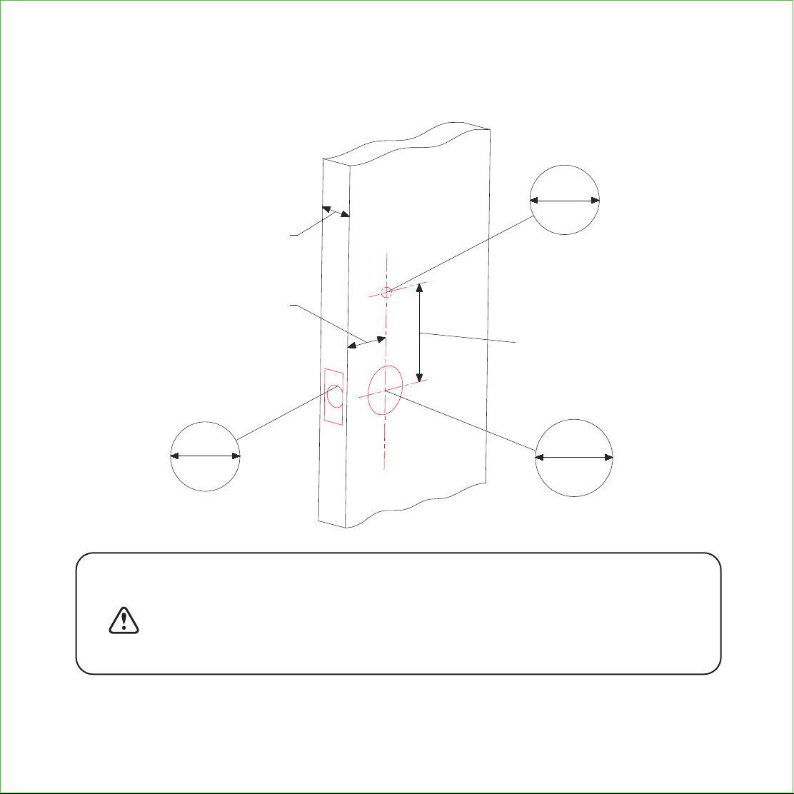
STEP 1: PREPARING YOUR DOOR
Make sure your door is prepared prior to installation. Please use the supplied
template for drilling holes if required.
IMPORTANT NOTICE
* You are not required to drill a hole in your door. We have provided
double sided adhesive tape for you to help stabilize the lock during
installation. Only drill a hole if you wish to have added stability.
Please refer to the provided templates for drilling if needed.
1"
25mm
1/2"
12mm
2-1/8"
54mm
3-109/127"
(98mm)
2-3/8"(60mm)
2-3/4"(70mm)
or
1-3/8"—2"
(35mm—50mm)
*
Drill Hole
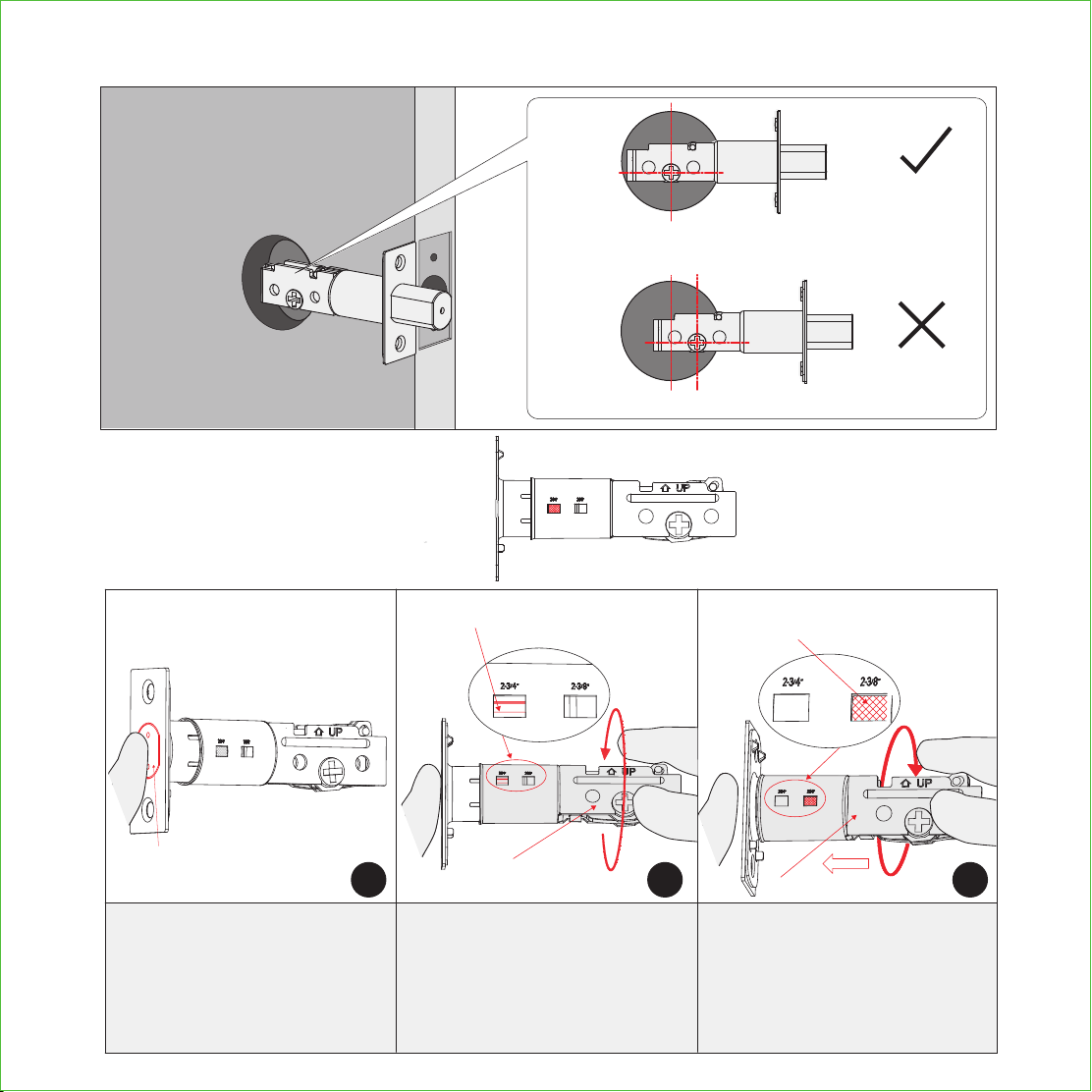
STEP 2: ADJUSTING THE DEADBOLT
If NOT, adjust deadbolt as shown below.
If the hole on the "+" is centered on the drilled
door hole, no adjustment is needed.
I. 2 ¾"(70mm) ---> 2 ⅜" (60mm)
(Note: Wear gloves during
adjustment to prevent pinching
your hands)
2. While holding the bolt (A),
twist deadbolt body (B) to
45-degree angle clockwise;
and
1. Make sure the bolt (A) is
plugged in and hold it tight
with left thumb;
3. Push deadbolt body (B)
towards the bolt (A) while still
holding the bolt tip tightly with
your left thumb. Twist deadbolt
body (B) counter-clockwise
until it snaps on 2 ¾" (C).
A
B
Deadbolt Body
Latch
The hole will snap on 2 ¾"
bumper (C) with a twist.
This part will unsnap with a twist.
1 2
Deadbolt at 2-¾" (70mm)
(shipping default status)
C
Deadbolt Body
3
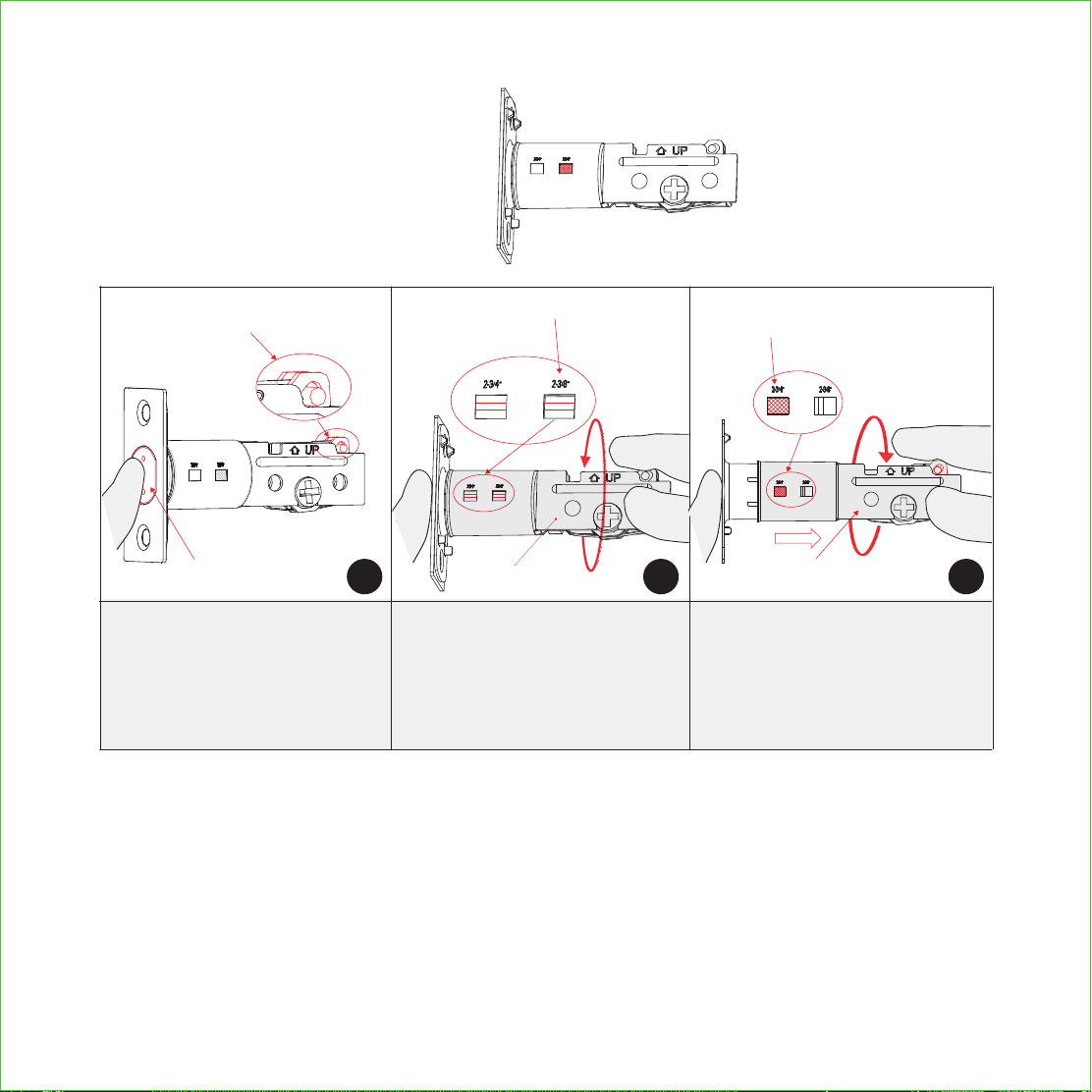
STEP 2: ADJUSTING THE DEADBOLT
Deadbolt at 2-⅜" (60mm)
II. 2 ⅜" (60mm) ---> 2 ¾" (70mm)
(Note: Wear gloves during
adjustment to prevent pinching
your hands)
A
B
E
D
Latch
Deadbolt Body
Deadbolt Body
31 2
2. Twist deadbolt body (B)
clockwise to 45-degree angle,
then
1. Make sure the bolt (A) is
plugged in and the crank (D)
is positioned at the end of the
deadbolt body (B);
3. Pull deadbolt body (B) about
½" away from the bolt (A).
Hold crank (D) then twist (B)
counter-clockwise until it snaps
on 2 ¾" (E).
The hole will snap on 2 ¾"
bumper (C) with a twist.
Make sure the crank (D) stays on this
position during the adjustment process.
This part will unsnap with a twist.
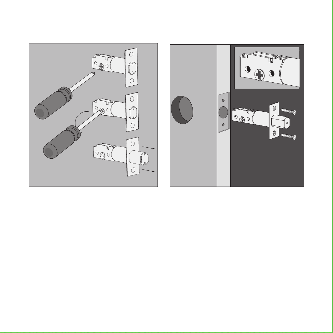
STEP 3: EXTENDING THE DEADBOLT
Extend the deadbolt as shown.
When installing the deadbolt, make sure
the deadbolt is fully extended and the
position of the "+" mark is on the bottom.
J
K(2X)
MAKE SURE THE DEADBOLT IS FULLY EXTENDED (LOCKED)
BEFORE INSTALLING PROCEEDING TO THE NEXT STEP
M
O
B
STEP 4: PREPARING THE EXTERIOR ASSEMBLY
*This hole (O) is for the optional Slotted Barrel Extension provided for stabilizing your lock. It
will require drilling extra
hole on your door (See template as provided). Alternatively, you
may use the double-sided adhesive tape provided
which serves the same purpose if you
do not want to drill a hole. If you drilled a hole, securely tighten
the post with a flathead
screwdriver by turning it clockwise before mounting on your door.
When the deadbolt is extended,
the torque blade should be kept
in a vertical position.
Vertical
O
Peel paper off the
Adhesive tape
*
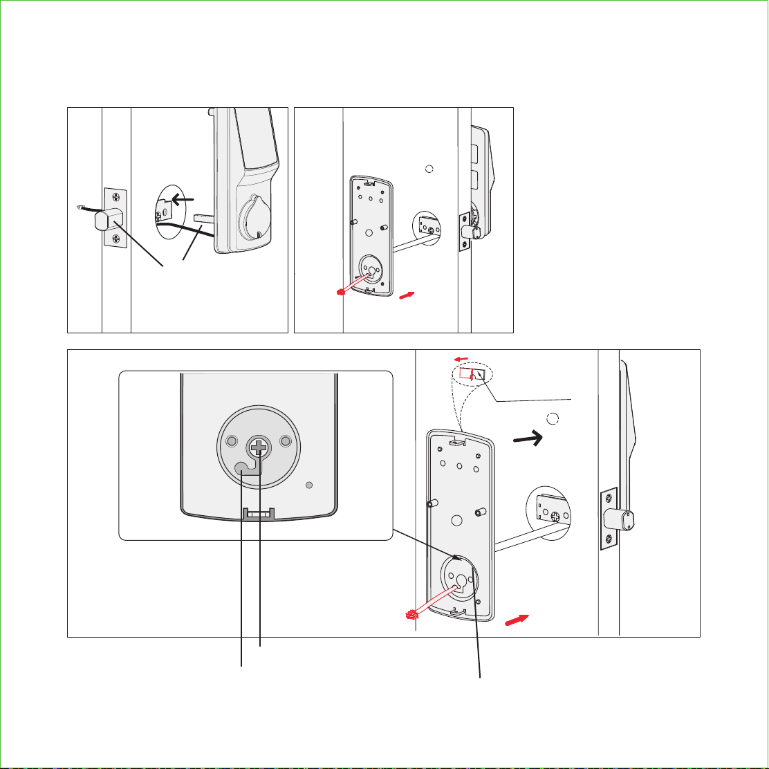
STEP 5: INSTALLING THE EXTERIOR ASSEMBLY
Note: Please rotate the
torque blade into the vertical
position for installation.
(2). Make sure the cable goes
underneath the latch.
(1). When the bolt is extended,
the torque blade should be kept
in a vertical position.
EXTERIOR VIEW
INTERIOR VIEW
(1)
Route cable through center hole, then push it into side hole.
Center Hole
Side Hole
(2)
(2)
Peel paper off the
Adhesive tape
G(2X)
E
Before screwing check the vertical
alignment for the mounting plate
and exterior assembly.
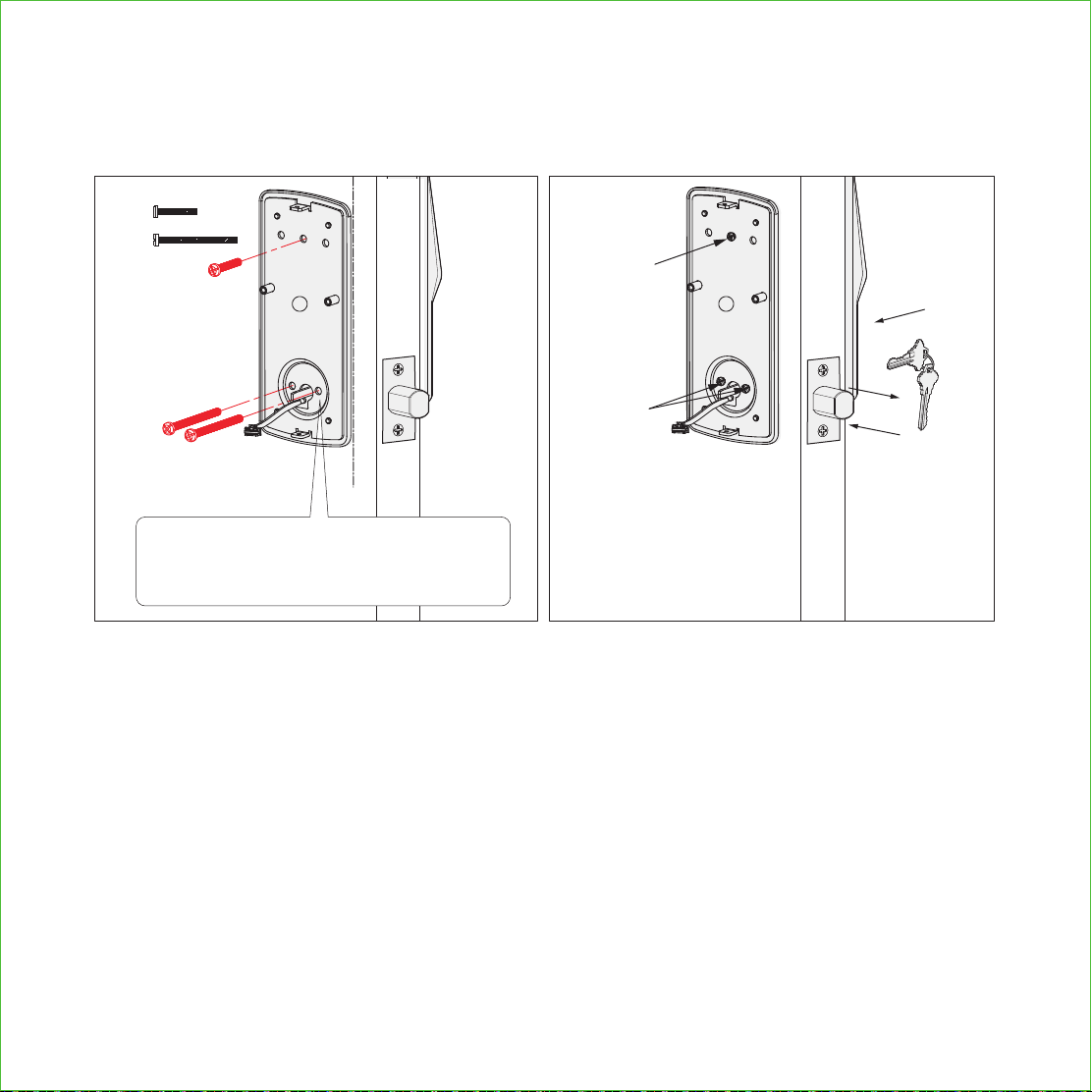
STEP 5 (CON’TD): INSTALLING THE EXTERIOR ASSEMBLY
After installation of the exterior assembly, use the physical key and try to unlock/lock
to check if the deadbolt is moving and not stuck. Do not forget to take out the key
before proceeding to next steps.
* E is only required if you drilled a hole in your door. If you did not drill a hole in your
door, please do not insert E.
Depending on your door thickness, use E1 or E2 screws for the doors.
Doors with thickness of 35-43mm, use E1. Doors with thickness of 43-50mm, use E2.
*
G(2X)
E
E1
E2
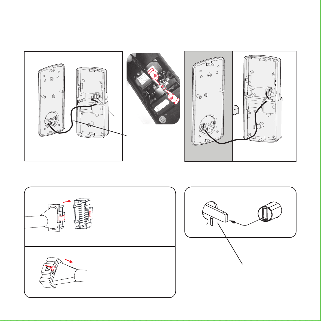
J
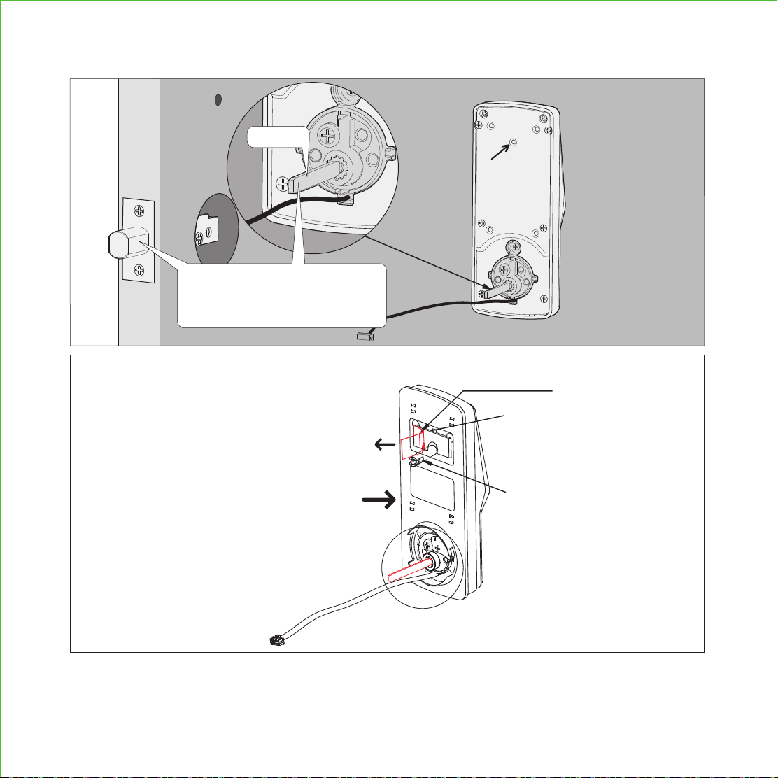
Connect the cable.
Plug the cable that is coming
through the door into the Interior
lock. Make sure you match the
direction of the plug correctly
and matching the red side of
the plug with the red side on the
lock. Secure the connection by
ensuring the snap is inserted
tightly.
In case you need to reinstall the
lock and disconnect the cable,
make sure to press the snap to
release the plug before carefully
pulling it out. Do not force to pull
the plug as this may result to lose
connection and damage the
lock.
Torque Blade Thumb turn shaft
Push the thumb turn shaft into the torque blade.
STEP 6: INSTALLING INTERIOR ASSEMBLY
MAKE SURE IT IS IN THE
VERTICAL POSITION
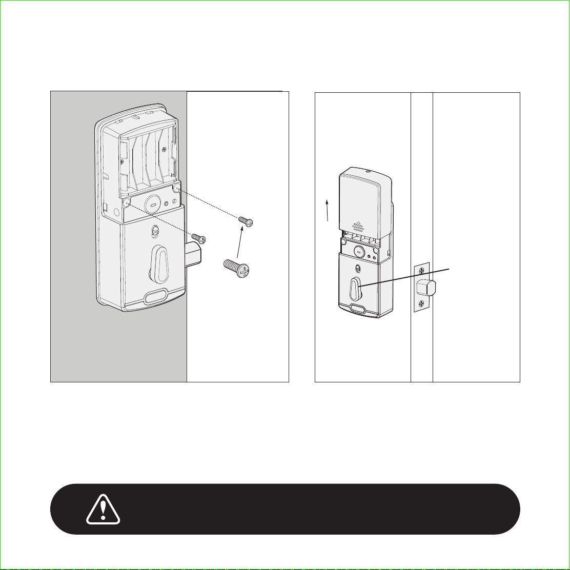
STEP 7: SECURING Lockly SECURE
Warning: Do not install the batteries yet!
I(2X)
P
Make sure the thumbturn (P) is in a vertical position.
Make sure the cover is removed so you can install batteries, but don’t install batteries
yet.
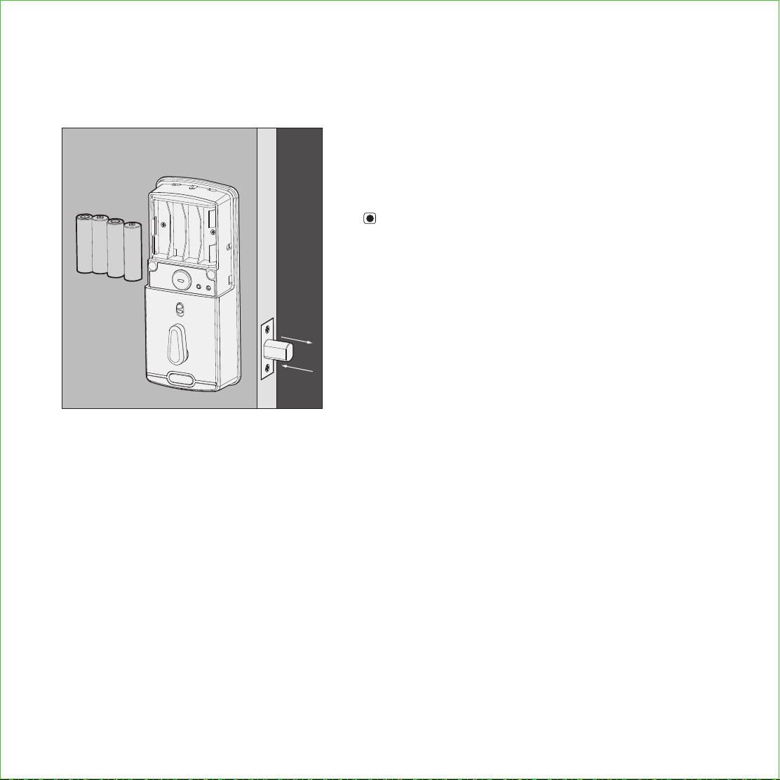
First install 3 of the 4 batteries. Before installing the
last battery, press and hold the PROGRAM button
while installing the last battery until you hear
a beep from Lockly.
Lockly will then perform a self check and the
keypad
screen will start to initiate. This self check will
automatically
determine and set your door lock to
a left open or right open door.
STEP 8: INSTALLING BATTERIES
The self-check process is very important step to ensure the installation is done properly.
After the lock finished the self-check, manually lock and and unlock your door by using
the thumb turn and the key to make sure the deadbolt moves smoothly. If you feel that
there is a tight tension while you are turning, it means that the lock may have not been
installed straight. Go back to Step 2 and re-install the lock.
To check if your lock was installed correctly, manually unlock your door by using the
thumb turn, then brush your hand across the screen on the outside. Your lock should lock
the dead bolt. If your lock automatically unlocks after it has been locked, it means that
your lock was installed incorrectly - proceed to Step 2 to make sure your lock was
installed with the dead bolt extended and the torque blade was inserted vertically while
the dead bolt was extended.
+
-
+
-
+
-
+
-
You have completed the Lockly Secure physical lock installation. You can add Live Monitoring
and Voice Assistant Control with the Google Assistant or Amazon Alexa via installing the Secure
Link Wi-Fi Hub and Door Sensor (included with Lockly Secure Pro and also sold separately).
Please proceed to next page for Secure Link Installation.
For Secure and Secure Plus, download the Lockly app from the iOS or Google Play app Store.
Follow on-screen instructions to complete your setup and installation.
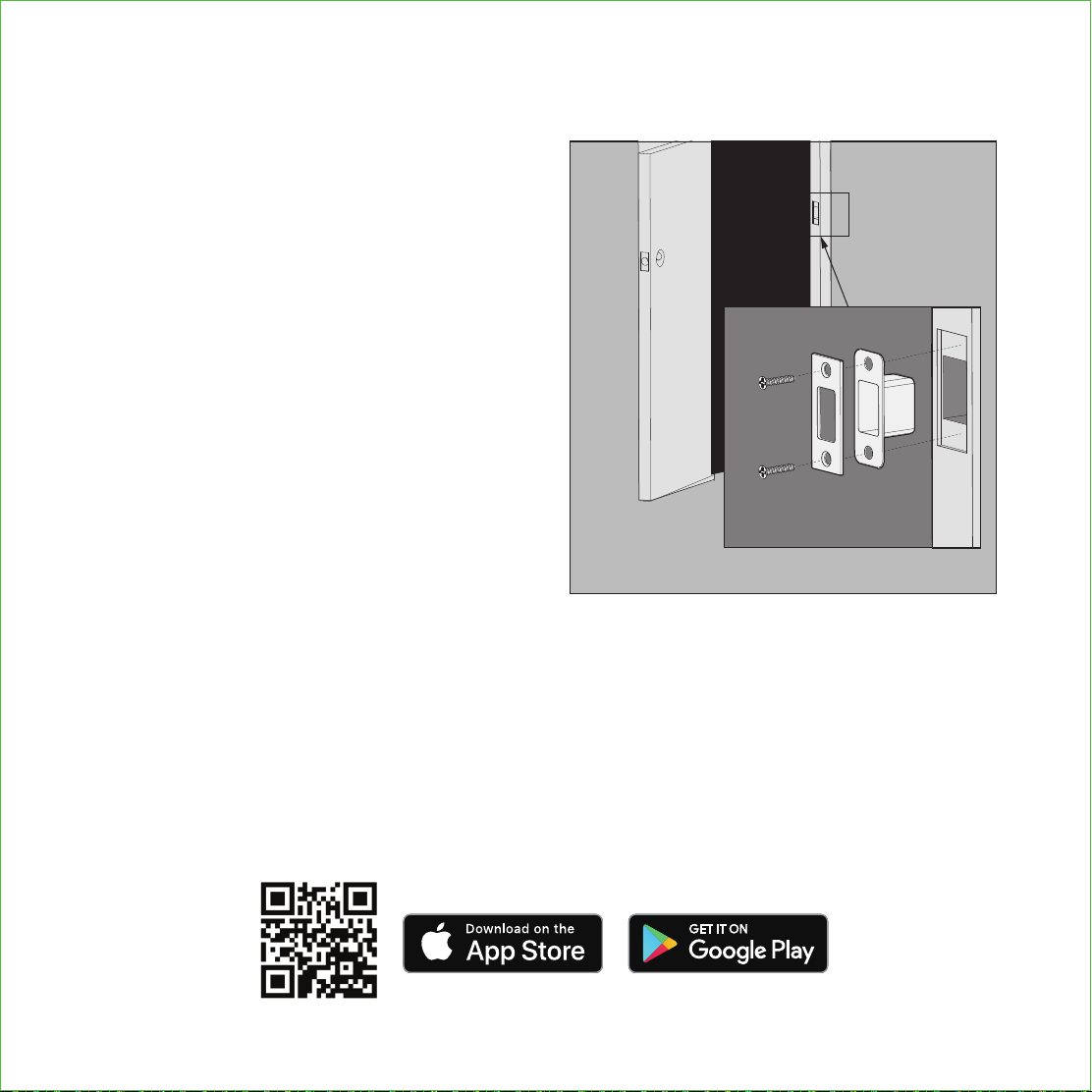
Install the door strike.
Install the door strike to your door frame and
proceed to the last step of installation of your
new lock. You may use our supplied door
strike or use your existing door strike as long as
the dead bolt moves smoothly in and out of
the door strike.
As there are many types of doors, you may
need to make slight adjustments so the dead
bolt moves smoothly. If anything is rubbing
against the deadbolt when locking and
unlocking, you may experience a warning
sound (rapid beeping) indicating that the lock
is experiencing misalignment or something is
blocking the deadbolt.
L
K(2X)
N
STEP 9: INSTALLATING DOOR STRIKE
Scan or visit Lockly.com/app
Scan or visit Lockly.com/app
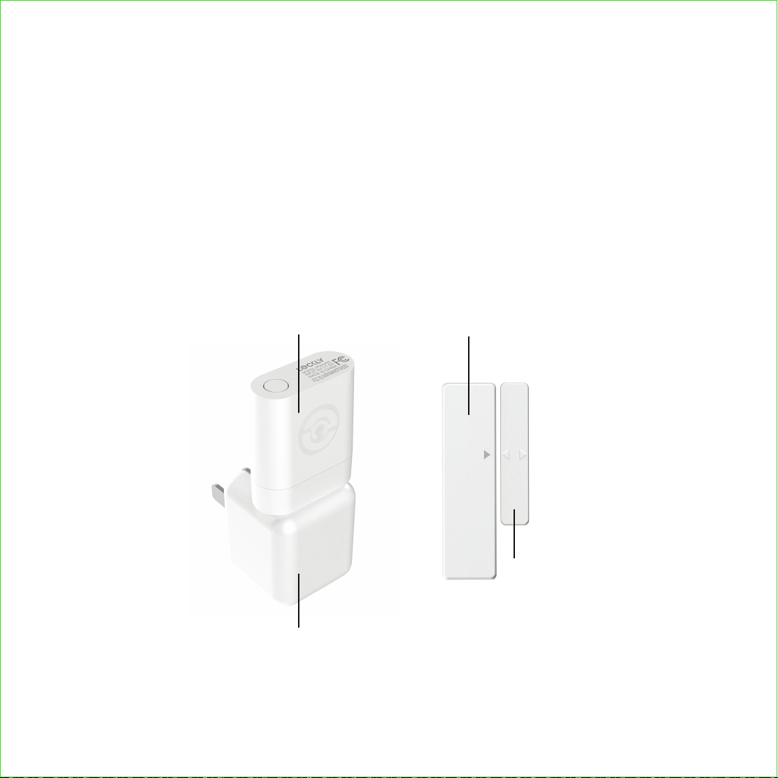
STEP 10: INSTALLING THE SECURE LINK WI-FI HUB
The Lockly Secure Link Wi-Fi Hub comes in two parts. Each part of the Secure Link
is crucial to enable voice assistant features and live monitoring and control of
your Lockly device.
The Wireless Door Sensor is optional but highly recommended as they provide the
ability to verify that your door is securely closed and not ajar.
Secure Link Wi-Fi Hub
USB 5V 1A AC Adaptor*
Wireless Door Sensor
LED Indicator
Door Sensor
PART A PART B
Door Frame Sensor
* You may plug the USB Secure Link Wi-Fi Hub into any UL Certified 5V 1A USB outlet, however
we recommend using ours for best performance. Power adaptor supplied in this box is based
on standard power plug and socket used by country.
In order for your Secure Link Wi-Fi Hub to connect to the internet, you must have a
Wi-Fi network with a radio signal emitting 2.4 GHz. All modern Wi-Fi devices support
2.4 GHz connections while some equipment supports both 2.4 GHz and 5 GHz.
Please check with your network administrator or internet provider if you’re unsure
what kind of network you have.
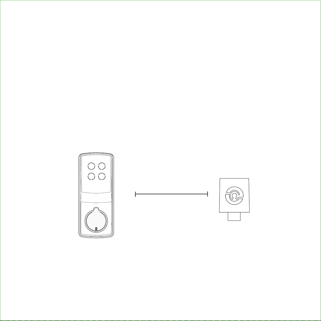
You should install the Secure Link Wi-Fi Hub after you have successfully finished
installation and set up of your Lockly Smart Lock. Refer to your appropriate
Lockly Smart Lock Installation Guide and User Manual that came with the lock for
reference.
The Secure Link Wi-Fi Hub (Part A) can be plugged into any standard 5V 1A USB
port or use the UL certified USB AC adapter included in this box (recommended).
For best connectivity, the Secure Link Wi-Fi Hub must be installed within 10 feet of
your Lockly Smart Lock. You may experience delayed or intermittent connectivity
if the Secure Link Wi-Fi Hub is installed further than 10 feet away from the Lockly
Smart Lock.
Lockly Smart Lock
Secure Link Wi-Fi Hub
(
Reference Image Only)
10 Feet
Distance Between
STEP 11: SETTING UP THE SECURE LINK WI-FI HUB
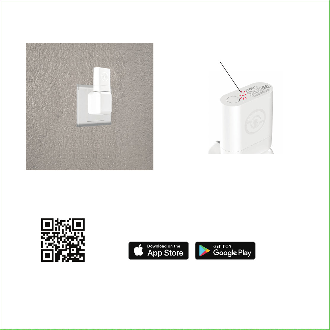
Plug the Secure Link Wi-Fi Hub into the 5V 1A USB AC adapter and plug the AC
adapter to your wall socket.
USA Outlet Shown
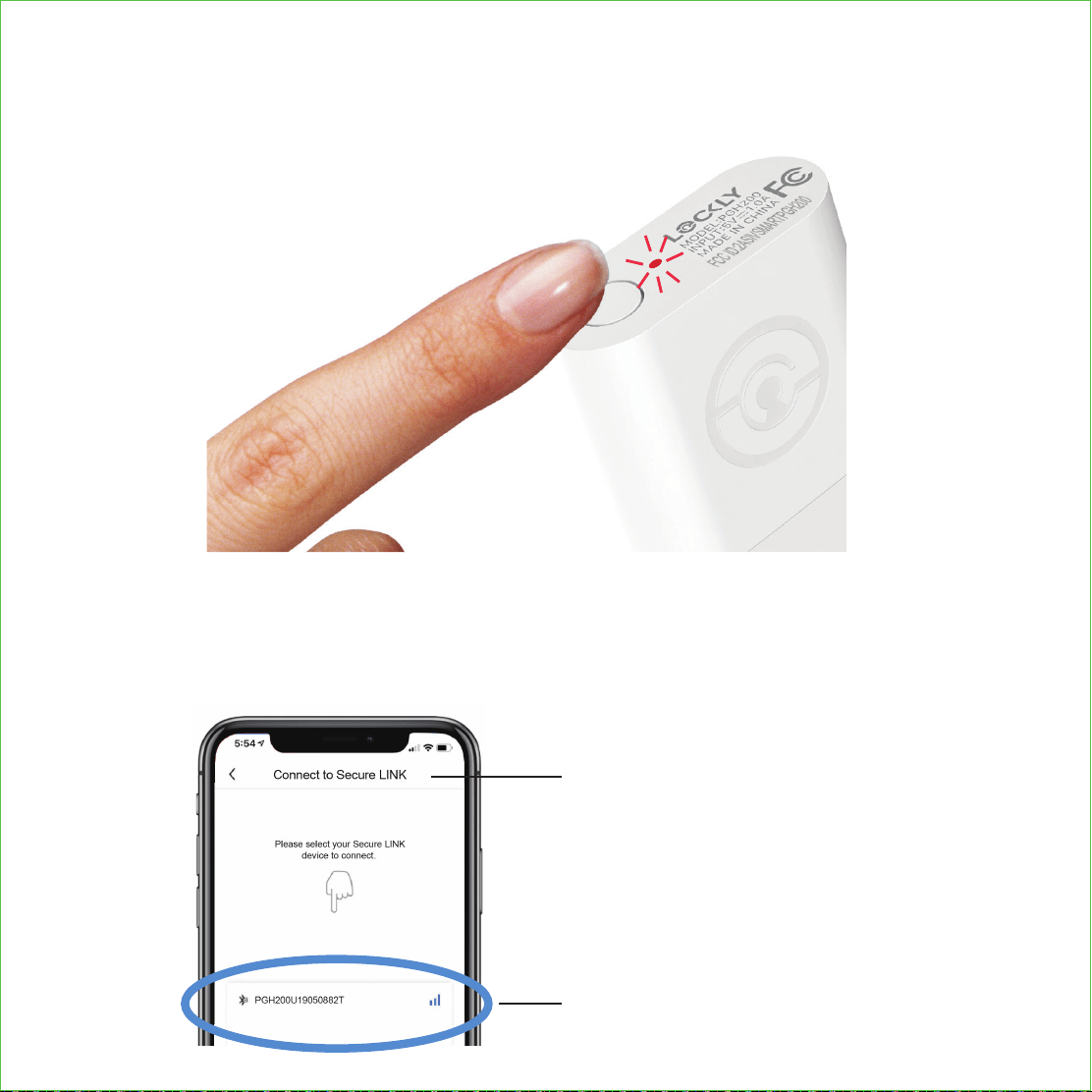
A RED LED indicator light will flash slowly
to indicate that the Wi-Fi Hub is ready to
connect.
LED Indicator is located next
to the Setup Button
Once you have confirmed that your Secure Link Wi-Fi Hub is ready to connect to
your lock, open the Lockly app to get started.
In case you have not downloaded our app, you can scan
the QR code to the left or visit https://lockly.com/app
Make sure you have already created an account and setup your Lockly device
to the Lockly app to continue.
Before you continue the Secure Link Wi-Fi Hub set up on your app, proceed to
the next
page to learn more about using the Secure Link Wi-Fi Hub and best
practices for connectivity.
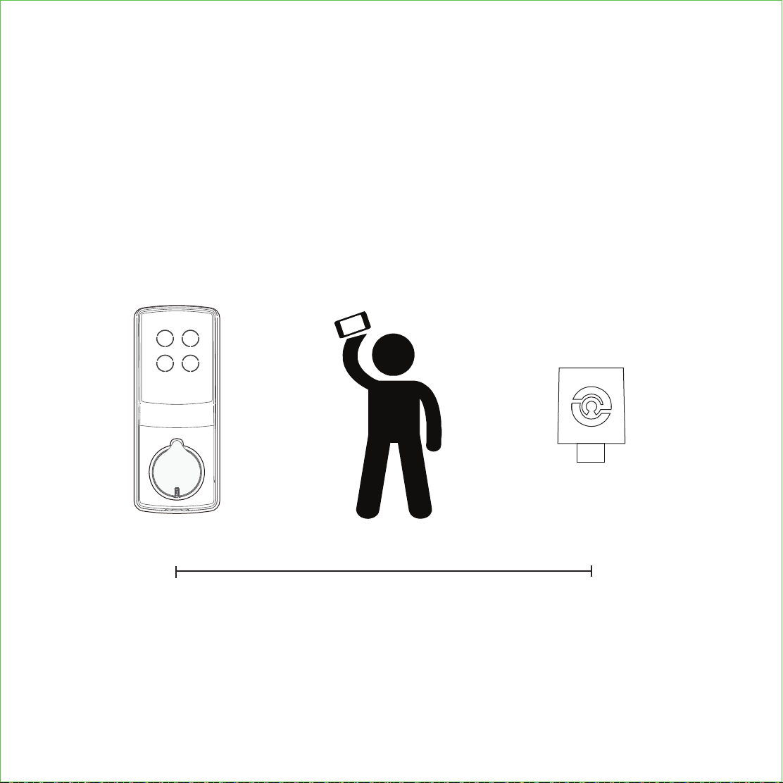
Before you set up your Wi-Fi Hub, make sure you are standing in between your Lockly
Smart Lock and Secure Link Wi-Fi Hub. For best connection, the distance between
the Wi-Fi Hub and your smart lock should be 10 feet or less.
10 Feet
Distance Between
Lockly Smart Lock
Shown
as reference only
Secure Link Wi-Fi Hub
Part A Shown Above
as reference only
You
Using an iOS or Android
Device with Bluetooth & Wi-Fi enabled
STEP 12: USING THE SECURE LINK WI-FI HUB
The Secure Link requires a strong wireless signal for optimal performance. Make sure
the Secure Link will be installed in a location with a strong 2.4 Ghz wireless signal.
Proceed to the next page to read how to finish set up of your Wi-Fi Hub.
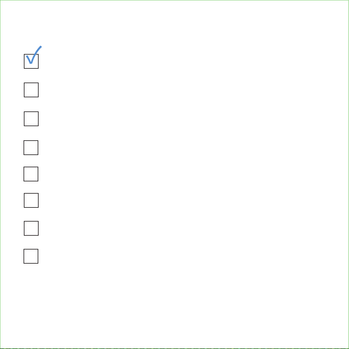
Secure Link Installation Checklist.
You have a Lockly Smart Lock already, and now adding the Wi-Fi Hub
The Secure Link Wi-Fi Hub is installed within 10 feet of your Lockly Smart Lock
You have the Lockly App installed on your iOS or Android device.
Your smartphone Bluetooth connection is ON and connected to your Lockly
device.
You are standing between your smart lock and the Secure Link Wi-Fi Hub.
Your Secure Link Wi-Fi Hub is located in a location with a strong Wi-Fi signal.
You are currently connected to a 2.4 GHz Wi-Fi Network (802.11 B/G/N)
on your iOS or Android device.
Be sure you check off the above 6 boxes before proceeding. If any of
the boxes are not checked, you may experience intermittent or delayed
response time in notifications.
I’m excited for my new Lockly smart lock, now compatible with Alexa and
the Google Assistant.
*Requires successful installation of the Secure Link Wi-Fi Hub
and connected to a strong internet connection
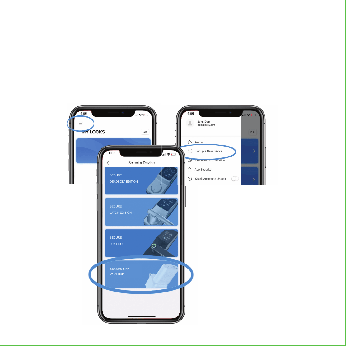
First, make sure the smartphone you are using to add the Wi-Fi Hub is connected to
your 2.4 GHz Wi-Fi Network. Next, open your Lockly App and select the main menu
from the upper left corner. (Image shown with iOS demo). Once the menu opens go
ahead select “Set up a New Device”
Select the Secure Link
Wi-Fi Hub on the bottom
NEXT >
STEP 13: CONFIGURING THE SECURE LINK WI-FI HUB
Press and Hold
3 Seconds
If you don’t see anything appear with a Bluetooth icon and a name starting with
PGH200... simply click the Refresh button on the upper right to rescan. Make sure
your Wi-Fi Hub is showing a flashing GREEN LED indicator and the Wi-Fi Hub is within
the optimal distance of 10 feet from your lock. Select the desired Wi-Fi Hub to continue.
connect to secure LINK
Minimum 2-3 Bars
Recommended
If you have never connected the Secure Link Wi-Fi Hub to your smart lock, the
Secure Link should have a slow flashing RED LED Indicator. Press and hold the Setup
Button located on the top of the Wi-Fi Hub for 3 seconds until you see the GREEN LED
Indicator start to rapidly flash.
Press and Hold
3 Second
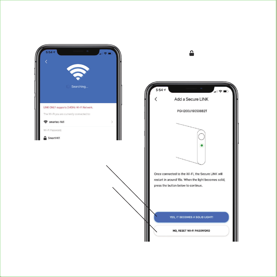
Enter your Wi-Fi password in the next
line next to the icon, then click
“Next Step” to continue.
If you are already connected to a 2.4 Ghz compatible Wi-Fi network, it should
display the network name. (See example below)
Select if your Wi-Fi Hub LED is
flashing GREEN.
*Actual screen may differ depending on device and app version
Please follow on -screen instructructions.
Select if your Wi-Fi Hub LED
Indicator light is ON and SOLID
GREEN.
NOTE: If the LED is flashing RED,
please check if your WiFi network
is properly working. Please check
with your network administrator or
internet provider if you’re unsure.
Congratulations! Your Secure Link Wi-Fi Hub
is now set up.
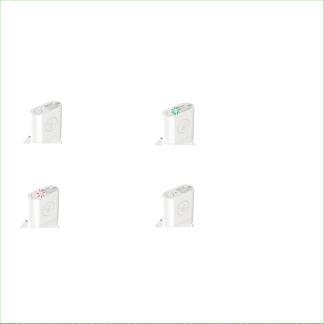
Below are some quick information for troubleshooting.
No Indicator Light
Your Wi-Fi Hub has no power.
Check your the power supply.
Slow RED Light Flashing
Your Wi-Fi Hub has power.
It’s not connected to any
wireless network.
Solid GREEN Light
Your Wi-Fi Hub is on and connected to
an active 2.4 Ghz wireless network.
Rapid GREEN
Light Flashing
Your Wi-Fi Hub is in setup mode.
Setup mode can be entered by pressing
the setup button for 2 seconds.
Setup mode will last approx 2 minutes.
CONTINUE TO NEXT PAGE TO INSTALL DOOR SENSOR >
Adding the door sensor (Part B) is optional, however we strongly recommend
installing the Door Sensor as it provides the ability to verify that your door is
securely closed and not ajar and also send push notifications to your phone on
the status of your door when someone opens and closes the door.
Depending on your door orientation, your Door Sensor will be mounted different
ways. The Door Sensor comes in two parts.
Door Sensor is required if you are intending to use Amazon Alexa or the Google
Home Assistant.
Part 1 - Door Frame Sensor
Part 2 - Door Sensor
Make sure you install the Door Sensor indoors on a clean and dry surface.
Gently wipe the surface of your door and door frame where you wish to install
the Door Sensor and make sure it’s dry before installing.
NEXT >
STEP 14: ADDING THE DOOR SENSOR
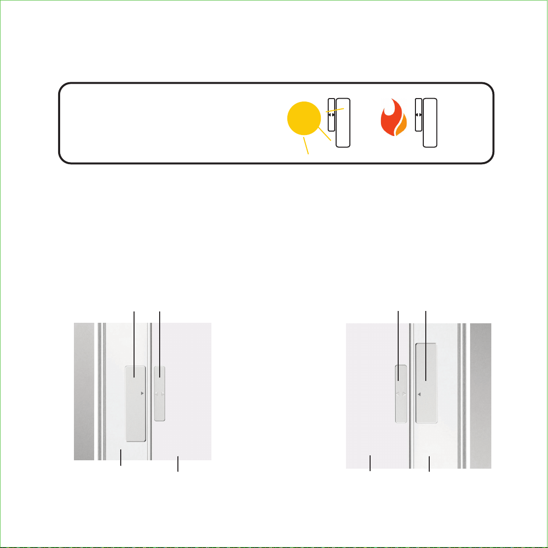
Keep the Door Sensor away from direct sunlight, high heat locations and large metal
objects that may interfere with wireless signals.
KEEP AWAY
The optimal location to install the Door Sensor is on the upper corners of your door,
away from the reach of children and pets.
Door Frame Door
Door Frame
Sensor
Door
Sensor
Door Door Frame
Door
Sensor
Door Frame
Sensor
DON’T INSTALL SENSOR YET. NEXT >
WHEN FACING YOUR DOOR
FROM THE INSIDE, DOOR HINGES
ARE ON THE RIGHT SIDE
WHEN FACING YOUR DOOR
FROM THE INSIDE, DOOR HINGES
ARE ON THE LEFT SIDE
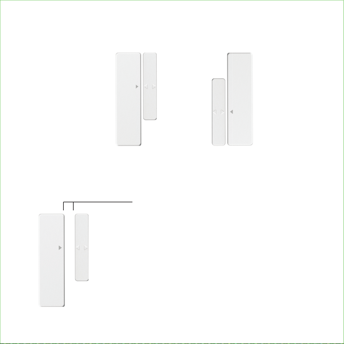
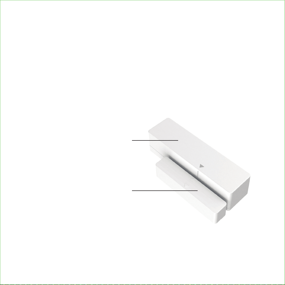
When you are installing the Door Sensor, make sure the arrows on the Door Sensor
is placed next to the arrow from the Door Frame Sensor.
OR
When installed on your door, the distance between the Door Sensor and the Door
Frame Sensor must be less than 3/4” in order for the sensor to work.
Gap - less than 3/4” when installed.
When you are ready to install, pull the plastic tab
at the back of the Door Frame Sensor to activate
the sensor.
Peel off the protective paper on the double sided
tape to expose the adhesive and apply securely
to your door and door frame.
NEXT >
Follow the On-Screen instructions on the app to
test your Door Sensor.
Congratulations! The Door Sensor is now set up.
The Secure Link Wi-Fi Hub works with other Smart Home devices. Check on the
status or remote lock and unlock your door by your voice using Amazon Alexa or
the Google Home Assistant.
To setup your lock to work with either of those platforms, download the Amazon
Alexa or the Google Home Assistant app and add a new skill with Amazon Alexa
or an Action with the Google Home Assistant.
For a full list of commands, help videos or to troubleshoot your
Secure Link Wi-Fi Hub visit us at https://lockly.com/help
Add the “Lockly” Skill (Alexa) and Action (Google)
then follow on screen instructions to finish set up.
NEXT >
Certified
FCC Warning:
This device complies with Part 15 of the FCC Rules. Operation is subject to the following two
conditions: (1) This device may not cause harmful interference, and (2) this device must accept
any interference received, including interference that may cause undesired operation.
NOTE 1: This equipment has been tested and found to comply with the limits for a Class B digital
device, pursuant to part 15 of the FCC Rules. These limits are designed to provide reasonable
protection against harmful interference in a residential installation. This equipment generates, uses
and can radiate radio frequency energy and, if not installed and used in accordance with the
instructions, may cause harmful interference to radio communications. However, there is no
guarantee that interference will not occur in a particular installation. If this equipment does cause
harmful interference to radio or television reception, which can be determined by turning the
equipment off and on, the user is encouraged to try to correct the interference by one or more of
the following measures:
- Reorient or relocate the receiving antenna.
- Increase the separation between the equipment and receiver.
- Connect the equipment into an outlet on a circuit different from that to which the receiver is
connected.
- Consult the dealer or an experienced radio/TV technician for help.
NOTE 2: Any changes or modifications to this unit not expressly approved by the party responsible
for compliance could void the user's authority to operate the equipment.
FCC Radiation Exposure Statement
The Secure Link Wi-Fi Hub complies with FCC radiation exposure limits set forth for an uncontrolled
environment. It should be installed and operated with minimum distance 20cm between the
radiator & your body.
IC WARNING
This device contains licence-exempt transmitter(s) that comply with Innovation,Science and Economic
Development Canada’s licence-exempt RSS(s).
Operation is subject to the following two conditions:

SECURE
IMPGD72820191024
We’re here to help!
https://lockly.com/help
(1) This device may not cause interference.
(2) This device must accept any interference, including interference that may cause undesired
operation of the device.
L’émetteur/récepteur exempt de licence contenu dans le présent appareil est conforme aux CNR
d’Innovation, Sciences et Développement économique Canada applicables aux appareils radio
exempts de licence. L’exploitation est autorisée aux deux conditions suivantes:
1. L’appareil ne doit pas produire de brouillage;
2. L’appareil doit accepter tout brouillage radioélectrique subi, même si le brouillage est susceptible
d’en compromettre le fonctionnement.
WARNING: This product contains DEHP and other chemicals known to the State of California
to cause cancer and birth defects, or other reproductive harm. For more information go to
www.P65Warnings.ca.gov

For an online version of this installation guide and videos, visit:
http://lockly.com/help
SECURE
