In order to continue serving our customers and providing the best products, our
product information including our user manuals may receive updates from time to
time. Please check our website for the latest user manuals and product materials.
Ver. 2.0 2/15/19

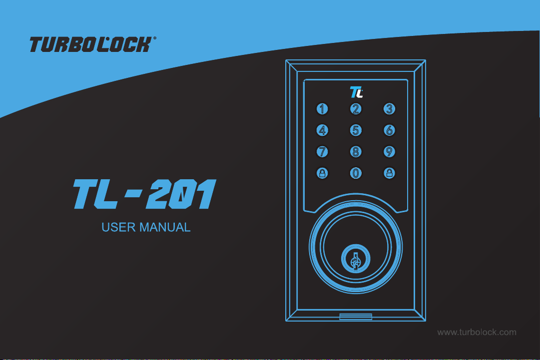
www.turbolock.com
Customer Service: 855-850-8031
TM

Section 1
Information & Safety Warnings 4
1.1 Introduction 4
1.2 Safety Warnings 4
1.3 End-of-Life Disposal 5
Section 2
Overview 6
2.1 Package Contents 6
2.2 Product Parts 7
2.3 Battery Information 8
Section 3
Installation (Retrot) 8
3.1 Pre-Installation 8
3.2 Main Installation 10
Section 4
Installation (New) 13
4.1 Pre-Installation 13
4.2 Main Installation 17
Section 5
Using the Lock 19
Section 6
Keypad Passwords 20
6.1 Changing the Admin Password 20
6.2 Adding User Passwords 20
6.3 Changing User Passwords 21
6.4 Deleting all User Passwords 22
6.5 Disguising Your Password 22
Section 7
Using the Mute Function 22
Muting/Un-muting 22
Section 8
Resetting the Lock 23
Option 1 23
Option 2 23
Section 9
Maintenance 24
Section 10
Troubleshooting 24
Section 11
Warranty 26
11.1 Violation 26
11.2 Information 26
Table of Contents

4 TurboLock TL - 201
Section 1
Information & Safety Warnings
1.1 Introduction
This user manual will guide you through the functions and usage of your TurboLock TL-201. It is important that you follow all
instructions and regard all notes that appear throughout this manual. Consult this manual before you attempt to use your lock.
If you have questions not answered by this manual or are in need of repair or non-routine service, contact customer service
at 855-850-8031. Before contacting customer service, please have your purchase information ready as this may be needed
during the call. This information may be recorded below.
Date of Purchase:
Place of Purchase:
1.2 Safety Warnings
When reading this manual, note these icons:
Notes with this icon MUST be read, understood, and obeyed to prevent injury or damage etc.
Notes with this icon include relevant information.
General Usage
• Never insert objects into the lock other than batteries as described in this manual.
• The lock is not a toy. Do not leave children unsupervised around the lock.
• Verify that all parts of the lock are accounted for. If any part is missing, contact customer service.
• The lock is best suited for standard doors made for buildings within the U.S.
• Use only the parts included in the original packaging or received from TurboLock.

TurboLock TL - 201 5
• Replace the batteries after receiving the lock’s low battery notication.
• Only use clean water, mild cleaner, and soft, non-abrasive cloth when cleaning.
• Never submerge the lock or any of the lock’s components.
• Never apply any cleaner directly to any part of the lock.
• Do not let water and liquids get into the lock’s electric parts or battery compartment.
• Objects should not be hung from the lock’s handles at any time.
• Installation surfaces must be level. Do not install on doors or surfaces with any type of deformity as gaps or warping may
cause the lock to malfunction or fail to operate entirely.
• Old and new batteries as well as batteries from dierent brands may not be mixed.
• Use only four AA batteries.
• Use the lock only as described in this user manual.
• If the battery compartment or surrounding parts are damaged, do not use the lock.
1.3 End-of-Life Disposal
This product must not be disposed of by incineration, landlling, or mixing with household trash. Improper disposal of the
battery contained within this product may result in the battery heating up, rupturing, or igniting which may cause serious injury.
The substances contained inside the battery present chemical risks to the environment. The recommended disposal for any
TurboLock TL-201 at its end-of-life is to dispose of the entire unit at or through an e-waste recycling center, program, or facility.
Local regulations and laws pertaining to the recycling and disposal of certain batteries and/or products containing them will vary
according to country, state, and local governments. You must check laws and regulations corresponding to where you live in
order to properly dispose of the battery and/or unit. It is the user’s responsibility to dispose of their waste equipment properly in
accordance with local regulations and laws.
For additional information about where you should drop o your batteries and electrical or electronic waste, please contact your
local or regional waste-management oce, your household waste disposal service, or your point-of-sale.
6 TurboLock TL - 201
Section 2
Overview
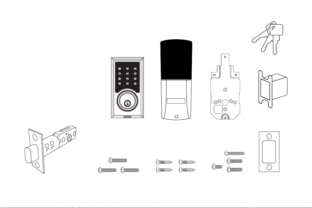
2.1 Package Contents
Outside Section 1x
Inside Section 1x
Plate 1x
Adjustable Latch Assembly 1x
Wood Screws 4x
Inside Screws 4x
Mounting Screws 3x
Keys 3x
Strike Box 1x
Strike Plate 1x
L R
2
3/4
”
2
3/8
”
2
3/4
”
2
3/8
”
2
3/4
”
2
3/8
”
2
3/4
”
2
3/8
”
2
3/4
”
2
3/8
”
Outside Section Inside Section Plate
Mounting Screws Inside ScrewsWood Screws
Keys
Adjustable Latch Assembly
2-3/8” (60 mm) or 2-3/4” (70 mm)
Strike Plate
Strike Box
TurboLock TL - 201 7
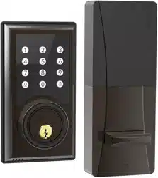
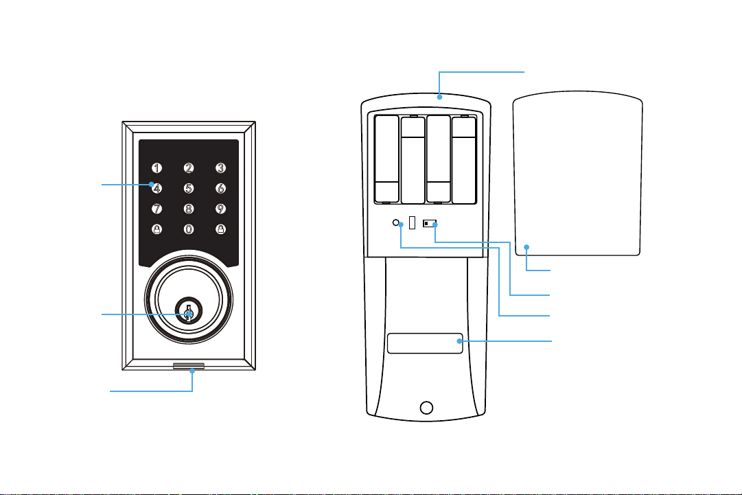
2.2 Product Parts
L R
Keyhole
Micro USB Port
Keypad
Battery Compartment
(Batteries not included.)
Battery Cover
L/R Switch
Reset Button
Thumb Turn

8 TurboLock TL - 201
2.3 Battery Information
The lock requires four standard or rechargeable ‘AA’ batteries which will be stored inside the back of the lock. New batteries
should be installed as soon as possible after receiving any low battery indication. After that rst notication, the lock will only
have enough power for approximately 50 uses before the batteries are fully depleted. This indication can be received from the
lock itself; the lock will beep after being unlocked. Expected battery life is approximately 365 days.
Section 3
Installation (Retrot)
This section details installation steps needed if you are installing the TL-201 on a door with a single cutout already
made. Replacing an older xture with a newer one is known as a retrot. If your door has never had a lock or
doorknob installed or otherwise has no cutout, please skip to page 13.
• For easier installation, have another person help hold the lock.
• Remove all parts of any old lock before installing the TL-201. In some cases, the old strike plate and/or box may be used.
• For your convenience, installation instructions are broken into segments. Read and follow the instructions for both Pre-
Installation and Main Installation.
• If your door happens to have two cut-outs, check the clearance between the two. Make sure there is enough distance so that
you may seal o any extra opening.
3.1 Pre-Installation
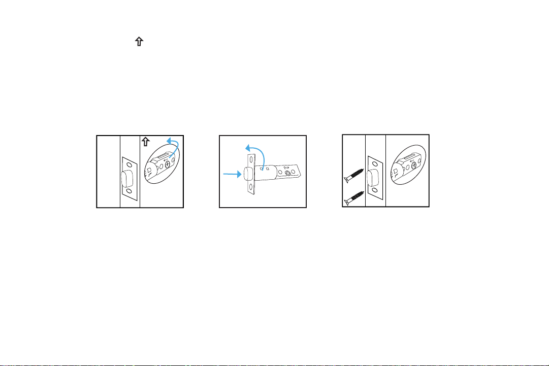
Part 1 Installing the Latch
KEEP DOOR OPEN AT ALL TIMES SHORTLY BEFORE, DURING AND SHORTLY AFTER INSTALLATION. If the lock is
incomplete or improperly installed, the lock and/or door may become stuck.
TurboLock TL - 201 9
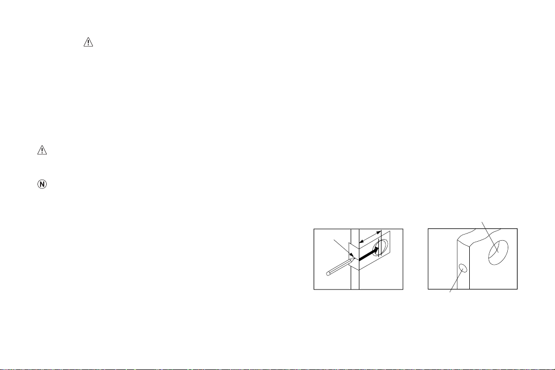
Step 1. Check the
UP
icon on the latch and insert it into the hole. The latch’s plate should sit ush against the edge of
the door. (Fig. 1) If there’s too much space behind the latch or if it’s sticking out of the door, the latch should be
adjusted. If the latch needs adjusting, continue on to Step 2; otherwise, skip to Step 3.
Step 2. Turn the latch and extend or retract it as needed. Make sure the metal peg pops into one of the two square holes in
the side and the deadbolt is pushed all the way in while adjusting the latch’s length. (Fig. 2) Insert the latch back into
the door.
Step 3. Add 2x wood screws and use a screwdriver (not included) to secure them. (Fig. 3)
Part 2 Installing the Strike
In most cases, the existing strike plate and setup can be used. If you wish to use the one included with your lock, refer to the
instructions for Part 3 on pages 15-16.
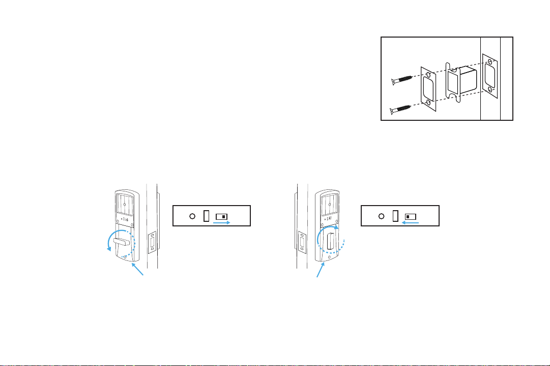
Part 3 Adjusting for Door Orientation
Step 1. With the door open, check it from the back and/or inside of the room. The lock’s parts should be oriented dierently
depending on whether the lock will be on the left side or right side of the door.
2
3/4
”
70
60
2
3/8
”
2
3/4
”
2
3/8
”
2
3/4
”
70
60
2
3/8
”
2
3/4
”
2
3/8
”
2
3/4
”
70
60
2
3/8
”
2
3/4
”
2
3/8
”
2
3/4
”
70
60
2
3/8
”
2
3/4
”
2
3/8
”
UP
2
3/4
”
70
60
2
3/8
”
2
3/4
”
2
3/8
”
2
3/4
”
70
60
2
3/8
”
2
3/4
”
2
3/8
”
(Fig. 1)
(Fig. 2)
(Fig. 3)
10 TurboLock TL - 201
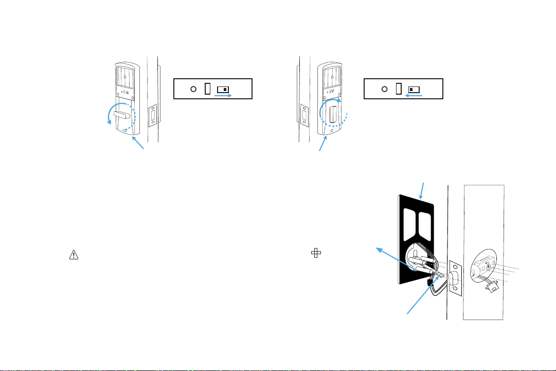
Step 2. Remove the battery cover from the inside section of the lock and adjust the L/R Switch and thumb turn as needed.
3.2 Main Installation
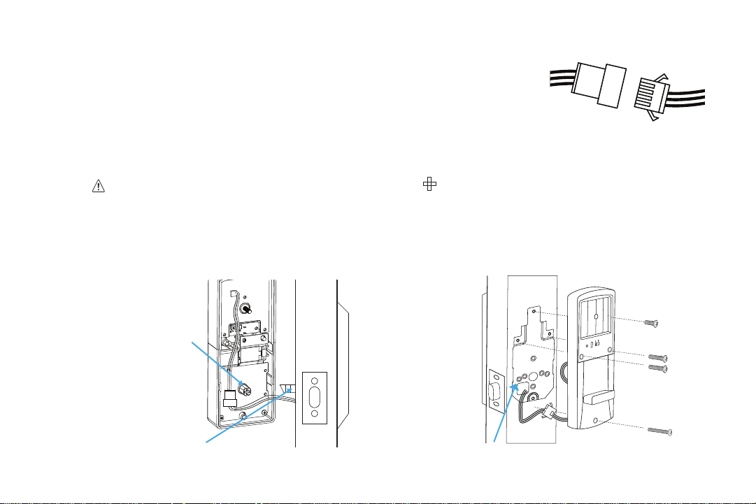
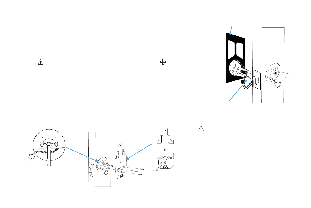
Step 1. Start with the outside section. Feed the power cables under
the latch and thread the latch pin and two of the pegs through
the latch. The third and lowest peg should be under the latch. If
needed, have someone hold the door itself or hold the outside
section at against the front of the door. (Fig. 4)
• Before threading the latch pin into the silver center part
and make sure the key is turned so it can easily be removed
from the keyhole. Make sure the latch pin is horizontal when
inserting.
• It’s highly recommended to leave the door open and keep the keys
in the lock during installation.
• Make sure the power cables are under the latch.
Latch on the right
L/R switch pushed to
R side + thumb turn
horizontal
Latch on the left
L/R switch pushed to
L side + thumb turn
vertical
L R
L R
L R
L R
Inside Section
Inside Section
2
3/4
”
2
3/8
”
Lowest Peg
(Fig. 4)
Silicone Backing
Latch Pin
TurboLock TL - 201 11
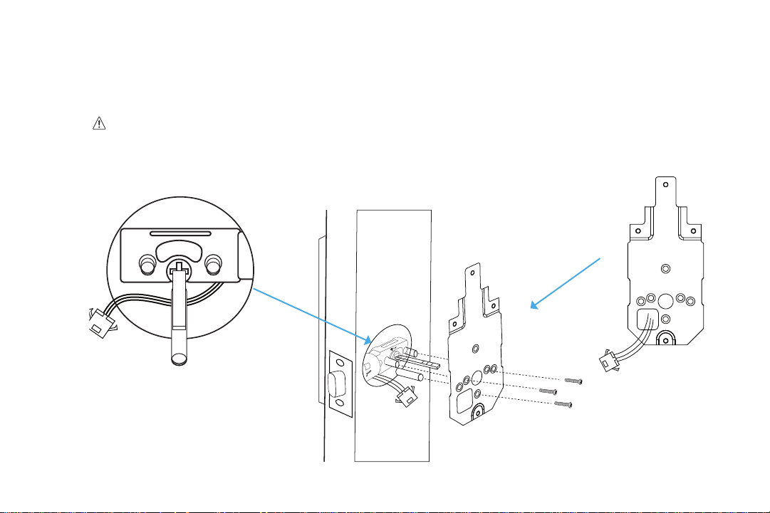
Step 2. Align the plate on the back of the door while making sure to thread the cables under the latch. Move the cables to
the corner hole of the plate. Thread the latch pin through the larger hole and match up the pegs with the smaller
surrounding holes. Use the 3x mounting screws to fasten the plate to the back of the door. Make sure all screws are
tightened. (Fig. 5)
• Check and adjust the plate or cables as needed to make sure the cables are tucked under the latch. Do NOT
force the screw through the cables as this will damage the lock and/or make it unusable.
• Thread the cables through the opening in the corner of plate.
2
3/4
”
2
3/8
”
2
3/4
”
70
60
2
3/8
”
2
3/4
”
2
3/8
”
2
3/4
”
70
60
2
3/8
”
2
3/4
”
2
3/8
”
(Fig. 5)
12 TurboLock TL - 201
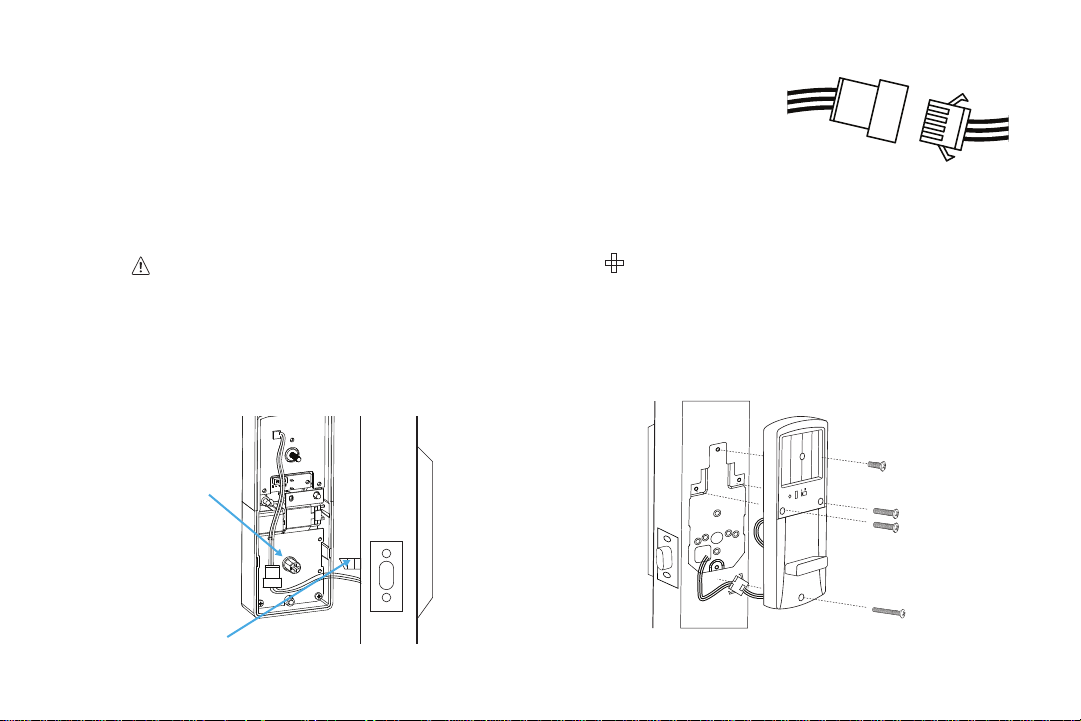
Step 3. Plug the cable into the inside section via the connectors. Make sure the lines
and notches from each connector are on the same side. (Fig.6)
Step 4. Check that the lock is set for the correct orientation. If needed, adjust the
switch and thumb turn according to the orientation needed for your door.
Step 5. Fit the inside section over the plate. Make sure to thread the latch pin into
silver center part and tuck the cords away from the lowest screw hole.
(Fig. 7)
If needed, tuck the cables inside the
door hole.
Before threading the latch pin into the silver center part , make sure the key is turned so it can easily be
removed from the keyhole.
Step 6. With the inside section at against the back of the door, use the 4 x inside screws to fasten it to the back of the door.
Note the placements for the dierent sized screws. (Fig 8.) Make sure all screws are tightened.
(Fig. 7)
(Fig. 6)
(Fig. 8)
Silver Center Part
Latch Pin
Plate
TurboLock TL - 201 13
Check and adjust the cables as needed to make sure they are tucked away from any screw hole opening. Do NOT
force the screw through the cables as this will damage the lock and/or make it unusable.
Step 7. Add batteries to the battery compartment, then slide the cover down over it. The lock should now be ready to use. It’s
highly recommended to use the keys and default password to test the lock to make sure it works before closing the
door. See Section 6 for information on the default admin password.
Section 4
Installation (New)
This section details installation steps needed if you are installing the TL-201 on a door without a cutout. If you are using
the TL-201 to replace an old lock or if your door otherwise already has a cutout, please go back to page 8.
• For easier installation, have another person help to hold the lock etc.
• For your convenience, installation instructions are broken into segments. Read and follow the instructions for both Pre-
Installation and Main Installation.
4.1 Pre-Installation
Part 1 Making the Opening
Step 1. Using the provided template, mark the locations for the
centers of the backset and the latch hole.
Step 2. Bore a 54mm (about 2” or 2 1/8”) hole on the door face, then drill a 25mm (about 1”) hole into the edge of the door
so that it intersects with the larger hole.
2” dia. hole
7/8” to 1” dia. hole
Backset
Latch Hole
Side Hole
14 TurboLock TL - 201
• When drilling the 54mm (about 2” or 2 1/8”) hole, it’s recommended to drill from both sides of door to prevent splintering.
• It may be easier to drill the 54mm hole with a hole saw bit (not included).
• It may be easier to drill the 25mm hole with a hole saw bit (not included) or a 7/8” spade bit (not included). If using a spade
bit, do not drill at high speeds as this may tear out extra wood and damage the door.
Part 2 Installing the Latch
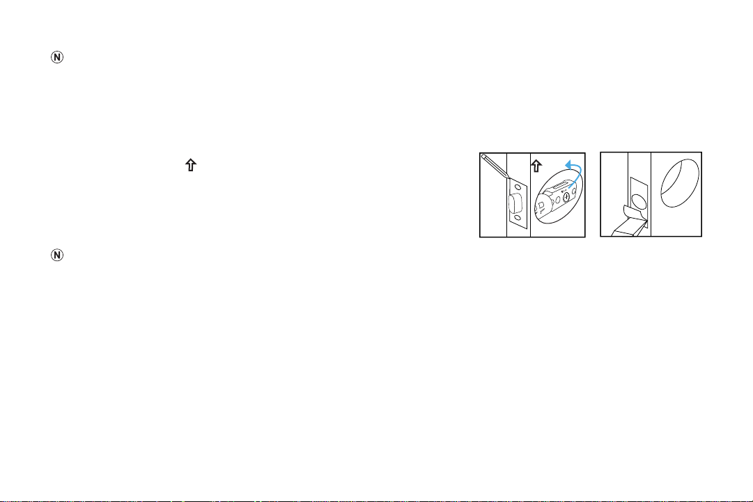
Step 1. Check the
UP
icon on the latch and insert it into the hole. Using
a pencil, mark a line around the edges of the latch to use as a
guide. After marking each side, remove the latch. (Fig. 9)
Step 2. Chisel about 3mm (0.1”) deep or until the latch plate sits ush with
the door edge. (Fig. 10)
During chiseling, it’s highly recommended to stop and reinsert the latch every
once in a while to see if it sits ush. If not, chisel a little more and check again. Be careful not to chisel too deep otherwise the
lock may not function correctly after installation.
Step 3. Insert the latch into the hole and check it. The latch’s plate should sit ush against the edge of the door. The latch
should be adjusted if there’s too much space behind it or if it’s sticking out of the door. If the latch needs adjusting,
move to Step 4. If it doesn’t need adjusting, skip to Step 5.
Step 4. Turn the latch and extend or retract it as needed. Make sure the metal peg pops into one of the two square holes in
the side and the deadbolt is pushed all the way after adjusting the latch. Insert the latch back into the door.
Step 5. Add 2x wood screws and use a screwdriver (not included) to secure them.
(Fig. 10)
UP
2
3/4
”
70
60
2
3/8
”
2
3/4
”
2
3/8
”
2
3/4
”
70
60
2
3/8
”
2
3/4
”
2
3/8
”
(Fig. 9)
TurboLock TL - 201 15
Part 3 Creating a Mortise & Installing the Strike
Step 1. Push the door until nearly closed and check where the latch’s bolt touches the frame.
Step 2. Use a pencil to mark the horizontal center of the latch on the door frame.
Step 3. Open the door again and extend the line over the edge of the door and inside the
frame.
Step 4. Measure the inside of the frame. Determine and mark the halfway point. From this
point, use a ruler to draw a line straight down so that it intersects the existing line.
Step 5. Use a 7/8” (22.2mm) spade bit and a drill to make two partially overlapping holes
approx. 0.6” (15mm) deep, centered above and below the center line. If needed, use
the chisel to make the hollow (aka “mortise”) more square. Note: If you choose to use
the strike box, you may need to chisel slightly deeper.
If using a spade bit, do not drill at high speeds as this may tear out extra wood and damage the
door or doorframe.
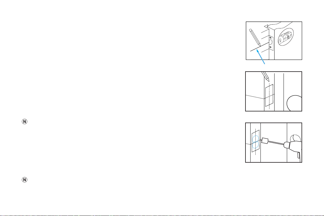
Step 6. Hold the strike plate over the mortise. Using a pencil, mark a line around the edges of
plate to use as a guide. After marking at the straight edges of the plate, remove the
plate.
Step 7. Chisel about 1.5mm deep or until the strike plate sits ush with the door frame. Note: If
you choose to use the strike box, you may need to chisel slightly deeper.
During chiseling, it’s highly recommended to stop and check that the strike plate sits ush in the doorframe over the strike box. If not,
chisel a little more and check again. Be careful not to chisel too deep; otherwise, the lock may not function correctly after installation.
2
3/4
”
70
60
2
3/8
”
2
3/4
”
2
3/8
”
2
3/4
”
70
60
2
3/8
”
2
3/4
”
2
3/8
”
16 TurboLock TL - 201
Step 8. Position the strike and strike box, then use a pencil to mark the center
points of the screw openings in the strike plate. Set the strike and strike
box aside and drill two small holes at each center point.
Step 9. Position the strike and strike box. Add the 2x remaining wood screws and
use a screwdriver (not included) to secure them.
Part 4 Adjusting for Door Orientation
Step 1. With the door open, check it from the back and/or inside of the room. The lock’s parts should be oriented dierently
depending on whether the lock will be on the left side or right side of the door.
Step 2. Remove the battery cover from the inside section of the lock and adjust the L/R Switch and thumb turn as needed.
Latch on the right
L/R switch pushed to
R side + thumb turn
horizontal
Latch on the left
L/R switch pushed to
L side + thumb turn
vertical
L R
L R
L R
L R
Inside Section
Inside Section
TurboLock TL - 201 17
4.2 Main Installation
Step 1. Start with the outside section. Feed the power cables under the latch and
thread the latch pin and two of the pegs through the latch; the third and
lowest peg should be under the latch. If needed, have someone hold the door
itself or hold the outside section at against the front of the door. (Fig. 10)
• Before threading the latch pin into the silver center part , make sure the key is
turned so it can easily be removed from the keyhole. Make sure the latch pin is
horizontal when inserting.
• It’s highly recommended to leave the door open and keep the keys in the lock
during installation.
• Make sure the power cables are under the latch.
Step 2. Align the plate on the back of the door while making sure to thread the
cables under the latch. Move the cables to the corner opening of the plate.
Thread the latch pin through the larger hole and match up the pegs with the smaller surrounding holes. Use the 3x
mounting screws to fasten the plate to the back of the door. Make sure all screws are tightened. (Fig. 11)
• Check and adjust the plate or cables
as needed to make sure the cables
are tucked under the latch. Do NOT
force the screw through the cables as
this will damage the lock and/or make
it unusable.
2
3/4
”
2
3/8
”
Silicone Backing
2
3/4
”
2
3/8
”
2
3/4
”
70
60
2
3/8
”
2
3/4
”
2
3/8
”
2
3/4
”
70
60
2
3/8
”
2
3/4
”
2
3/8
”
(Fig. 10)
(Fig. 11)
Latch Pin
18 TurboLock TL - 201
Step 3. Connect the cables to the connectors. Make sure the lines and notches from
each connector are on the same side.
Step 4. Check that the lock is set for the correct orientation. If needed, adjust the
switch and thumb turn according to the orientation needed for your door.
Refer to the images on page 16.
Step 5. Fit the inside section over the plate. Make sure to thread the latch pin into silver center part and tuck the cords away
from the lowest screw hole. (Fig. 12) If needed, tuck the cables inside the door hole.
Before threading the latch pin into the silver center part , make sure the key is turned so it can easily be
removed from the keyhole.
Step 6. With the inside section at against the back of the door, use the 4x inside screws to fasten it to the back of the door.
Note the placements for the dierent sized screws. (Fig. 13) Make sure all screws are tightened.
(Fig. 12) (Fig. 13)
Silver Center Part
Latch Pin

TurboLock TL - 201 19
Check and adjust the cables as needed to make sure they are tucked away from any screw hole opening. Do NOT
force the screw through the cables as this will damage the lock and/or make it unusable.
Step 7. Add batteries to the battery compartment, then slide the cover down over it. The lock should now be ready to use.
It’s highly recommended to use the keys and default password to test the lock to make sure it works before closing
the door. See Section 6 for information on the default admin password.
Section 5
Using the Lock
In general, there are two ways to unlock your door: using keys or using the keypad to enter the password, then pressing the
button. The lock will engage.
Regardless of unlock method, the TL-201 will not lock again on its own. To lock the door, close it, wait for the keypad light turns
o, then press the button. The lock will engage and lock the door. If the keypad lights up, press the button twice to lock
the door. (Pressing the lock button once will turn o the backlight. Pressing the lock button twice engages the lock.)
Using the Admin Password
Enter the Admin Password on keypad, and then press the
button. The lock will engage allowing you to open the door. Note,
the Admin Password must be changed from the default password. See Section 6.
Using a User Password
Enter the password received from the admin, and then press the
button. The lock will engage allowing you to open the door.
• The TL-201 also features a Mute Function. See Section 7.

20 TurboLock TL - 201
• If a password has been entered wrong 5x in a row, the lock will go into a 15-minute period of inactivity where it cannot be
used. This is a security feature designed to prevent unwanted parties from using the lock.
Section 6
Keypad Passwords
6.1 Changing the Admin Password
• Admin passwords must be 4~6 digits long.
• The default Admin Password is ‘123456’.
• For security, it is highly recommended that you change the Admin Password from the default.
Step 1. First, make sure the TL-201 is fully unlocked. Then, use the keypad to enter the default (‘123456’) or current Admin
Password, then press the button.
Step 2. Wait for the backlight to ash red and then blue again. Quickly enter ‘1’ and press the button before the light
turns o.
Step 3. Enter the new Admin Password, and then press the button. The lock should beep to conrm the change. If
desired, test the new password afterwards.
The new password must be entered while the blue backlight is on. If it goes out, begin again at Step 1.
6.2 Adding User Passwords
• The admin must create passwords for users.

TurboLock TL - 201 21
• User passwords must be 4~6 digits long.
• Do not use the same combination for admin and user passwords.
Step 1. First, make sure the TL-201 is fully unlocked. Use the keypad to enter the current Admin Password, then press the
button.
Step 2. Wait for the backlight to ash red and then blue again. Quickly enter ‘2’ and press the button before the light
turns o.
Step 3. Enter the new 4~6 digit user password, and then press the button. The lock will beep to conrm the password
was added.
Step 4. Repeat step 3 with dierent passwords to add multiple user passwords (up to 20 at a time). Note: all passwords
must be entered and while the backlight remains on.
Step 5. Passwords can now be given to users as needed.
6.3 Changing User Passwords
• To change user passwords, you must use the current user passwords to open the lock rst.
• User passwords must be 4~6 digits long.
Step 1. Make the TL-201 is fully unlocked. Use the keypad to enter the current User Password, then press the button.
Step 2. Wait for the backlight to ash red and then blue again. Quickly enter ‘3’ and press the button before the light
turns o.

22 TurboLock TL - 201
Step 3. Enter the new 4~6 digit user password, and then press the button. The lock will beep to conrm the change. If
desired, test the new password afterwards.
6.4 Deleting all User Passwords
First, make sure the TL-201 is fully unlocked. Then, use the keypad to enter the current Admin Password, then press the button.
The lock should beep and the backlight should turn blue again. Quickly enter ‘4’ and press the button before the light turns o. All
user passwords will then be erased.
6.5 Disguising Your Password
This function is an added security feature aimed at preventing password theft. With Passcode Disguise, you may enter 12 digits into
the keypad. As long as the correct password sequence is entered, regardless of how many digits were entered before or after, the
TL201 will unlock.
For example, if your user password is “0808“, you can enter digits before and/or after you enter “0808” to confuse any unwanted
party who may be watching. In this case, “113540808”, “110808”, “108081”, and “208082256977” and so on will all successfully
open the door while concealing your password.
Section 7
Using the Mute Function
USE WITH CAUTION. Remember to turn o the function when it is no longer needed. Do not leave this function on for
extended periods of time.
Muting/Un-muting
Step 1. First, make sure the TL-201 is fully unlocked. Then enter the current Admin Password and press the button.

TurboLock TL - 201 23
Step 2. Wait for the backlight to ash red and then blue. Quickly enter ‘8’ and press the button before the light turns o.
Section 8
Resetting the Lock
• Resets cannot be reversed.
• Performing a reset will delete all passwords including the Admin Password.
• Once all passwords are erased, only the default Admin Password can open the lock.
• After a reset:
○ Admin Password will return to its default ‘123456’.
○ Choose a new Admin Password immediately. See Section 6.
Option 1
Step 1. Remove the cover from the battery compartment at the back of the lock.
Step 2. Press and hold the reset button for at least three seconds.
Option 2
Step 1. First, make sure the TL-201 is fully unlocked. Use the keypad to enter the Admin Password, then enter .
Step 2. Wait for the backlight to ash red and then blue. Enter ‘9’ and then press before the blue back light turns o.
The TL201 will automatically reset anytime the lock is removed and/or the any internal cables are disconnected and
reconnected.

24 TurboLock TL - 201
Section 9
Maintenance
Proper cleaning and maintenance of your lock ensures it will continue to work as it should.
• The keypad is made of acrylic. Use water and soft, non-abrasive cloth when cleaning.
• If a mess cannot be cleaned with water, apply a gentle cleaner to the cloth and clean.
• Do not apply any cleaner or detergent directly to any part of the lock.
• After cleaning with any cleaner, apply clean water to a new, non-abrasive cloth, wipe the lock clean, and dry so as not to leave
residue on the lock.
• Do not let water and liquids get into the lock’s electric parts or battery compartment.
Section 10
Troubleshooting
If none of the following resolves your issue, please visit our website at www.turbolock.com or contact customer service at
855-850-8031.
Problem Possible Cause Solution(s)
Why can’t I open the door?
Too much time has passed.
Turn the handle to open the door while the lock’s
backlight is still on.
Your access has been restricted.
If you received a key from the lock’s admin, your access
may be restricted to certain times of the day etc. Check
with your admin regarding these details.

TurboLock TL - 201 25
Problem Possible Cause Solution(s)
Why does the lock jam? /
The door doesn’t close.
The latch size is wrong.
Disassemble the lock and check the latch assembly. If
retrotting, check the latch length and adjust as needed.
If installed on a new door, adjust the latch and/or, drill into
the door to t the latch as needed.
The strike plate and latch aren’t
correctly aligned.
Open the door and check the alignment of both the latch
and the strike plate. Adjust as needed.
The lock doesn’t work.
The lock isn’t receiving power.
Ensure the batteries are properly installed. Remove and
reinstall if needed.
The batteries are entirely dead and/or
were not replaced in a timely manner.
Replace the batteries.
Use the micro USB port to power the lock so that the
door opens. Replace the batteries.
I entered the password
wrong (at least 5x).
If a password has been entered
wrong 5x in a row, regardless of the
entry method, the lock will go into a
15-minute period of inactivity where
it cannot be used. This is a security
feature designed to prevent unwanted
parties from using the lock.
Wait 15 minutes and try again.
Why is the lock beeping
multiple times?
I forgot my codes. The codes were not properly recorded.
Perform a reset in order to erase all passwords. In
order to perform a reset, you must have access to the
back of the door. Once a reset is performed, record the
passwords in memory or a secure location.

26 TurboLock TL - 201
Section 11
Warranty
11.1 Violation
The lock cannot be repaired or serviced within its warranty if any of the following has occurred:
• The warranty has expired.
• Damage occurred during or in relation to non-routine and/or unauthorized disassembly.
• Failure to provide a valid proof of purchase when requesting service or repair.
• Damage occurred as a result of natural disaster etc.
• Damage occurred due to unexpected factors or man-made reasons (including mis-operation, uid found in any openings, improper
insertion or pulling, hauling, bumping, improper voltage input and others).
11.2 Information
One-Year Limited Hardware Warranty
Your TurboLock TL-201 (“Product”) includes a One-Year Limited Hardware Warranty (“Warranty”). The Warranty covers product
defects in materials and workmanship under normal use. This Warranty is limited to residents of the United States and Canada and
is available only to original purchasers. This Warranty gives you specic legal rights and you may also have other rights which vary
from state to state.
This Warranty starts on the date of your purchase and lasts for one year (the “Warranty Period”). The Warranty Period is not
extended if the Product is repaired or replaced. We may change the availability of this limited warranty at our discretion, but any
changes will not be retroactive.
Warranty services are provided by Warranty Pro (“WP”). If a hardware defect arises and a valid claim is received within the Warranty
Period, at its option and to the extent permitted by law, WP will: (1) repair the hardware defect by using new or refurbished parts that
are equivalent to new in performance and reliability; or (2) exchange the Product with a product that is new or refurbished which is
substantially equivalent to the original product. This Warranty is for one replacement only of like-items and does not cover items out

TurboLock TL - 201 27
of production if the product is no longer made or stocked. This Warranty is not assignable or transferable. The original purchaser
may call the toll-free number at 855-850-8031 for service requests.
When a product or part is exchanged, any replacement item becomes your property and the replaced item becomes WP’s property
.
This warranty only covers technical hardware defectiveness during the warranty period and under normal use conditions. WP does
not warrant uninterrupted or error-free operation of this Product.
This Warranty does not cover any damage due to: (a) transportation; (b) storage; (c) improper use; (d) failure to follow the product
instructions or to perform any preventive maintenance; (e) modications; (f) unauthorized repair; (g) normal wear and tear; or (h)
external causes such as accidents, abuse, or other actions or events beyond our reasonable control.
Important: Do not disassemble the Product. Disassembling the Product will void this Warranty. Only WP or a party expressly
authorized by WP should perform service on this Product.
DISCLAIMER OF WARRANTY: THE REMEDIES DESCRIBED ABOVE ARE YOUR SOLE AND EXCLUSIVE REMEDIES
AND OUR ENTIRE LIABILITY FOR ANY BREACH OF THIS LIMITED WARRANTY. OUR LIABILITY SHALL UNDER NO
CIRCUMSTANCES EXCEED THE ACTUAL AMOUNT PAID BY YOU FOR THE DEFECTIVE PRODUCT, NOR SHALL WE UNDER
ANY CIRCUMSTANCES BE LIABLE FOR ANY CONSEQUENTIAL, INCIDENTAL, SPECIAL OR PUNITIVE DAMAGES OR
LOSSES, WHETHER DIRECT OR INDIRECT.
SOME STATES DO NOT ALLOW THE EXCLUSION OR LIMITATION OF INCIDENTAL OR CONSEQUENTIAL DAMAGES, SO
THE ABOVE LIMITATION OR EXCLUSION MAY NOT APPLY TO YOU.
THE DURATION AND REMEDIES OF ALL IMPLIED WARRANTIES, INCLUDING WITHOUT LIMITATION THE WARRANTIES OF
MERCHANTABILITY AND FITNESS FOR A PARTICULAR PURPOSE ARE LIMITED TO THE DURATION OF THIS EXPRESS
LIMITED WARRANTY.

TM
COPYRIGHT @ 2018 TURBOLOCK. ALL RIGHTS RESERVED.