Owner's Guide Tools - Home Improvement
Overview
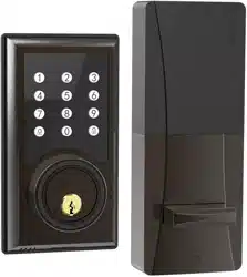
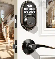
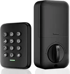
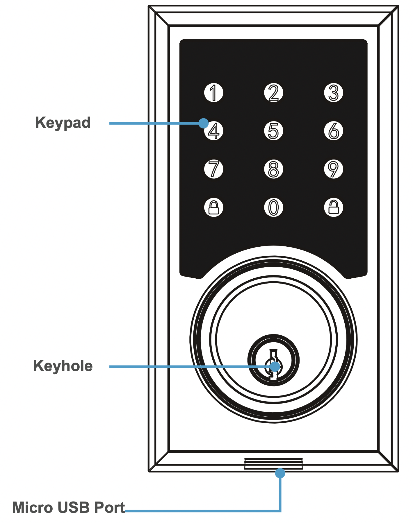
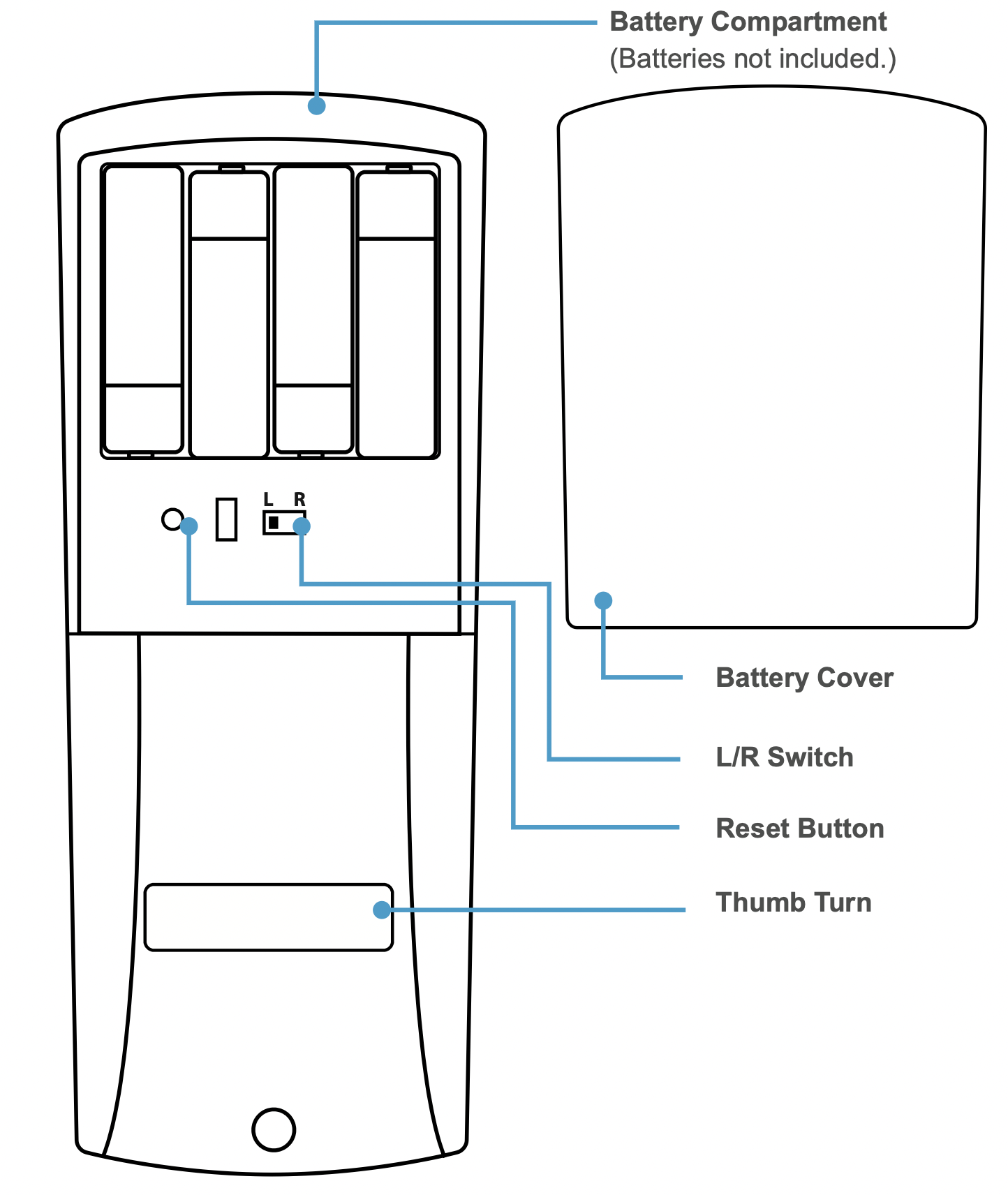
Product Parts
Installation (Retrofit)
This section details installation steps needed if you are installing the TL-201 on a door with a single cutout already made. Replacing an older fixture with a newer one is known as a retrofit. If your door has never had a lock or doorknob installed or otherwise has no cutout, please skip to page 13.
Note:
- For easier installation, have another person help hold the lock.
- Remove all parts of any old lock before installing the TL-201. In some cases, the old strike plate and/or box may be used.
- For your convenience, installation instructions are broken into segments. Read and follow the instructions for both PreInstallation and Main Installation.
- If your door happens to have two cut-outs, check the clearance between the two. Make sure there is enough distance so that you may seal off any extra opening.
Pre-Installation
Installing the Latch
Warning: KEEP DOOR OPEN AT ALL TIMES SHORTLY BEFORE, DURING AND SHORTLY AFTER INSTALLATION. If the lock is incomplete or improperly installed, the lock and/or door may become stuck.
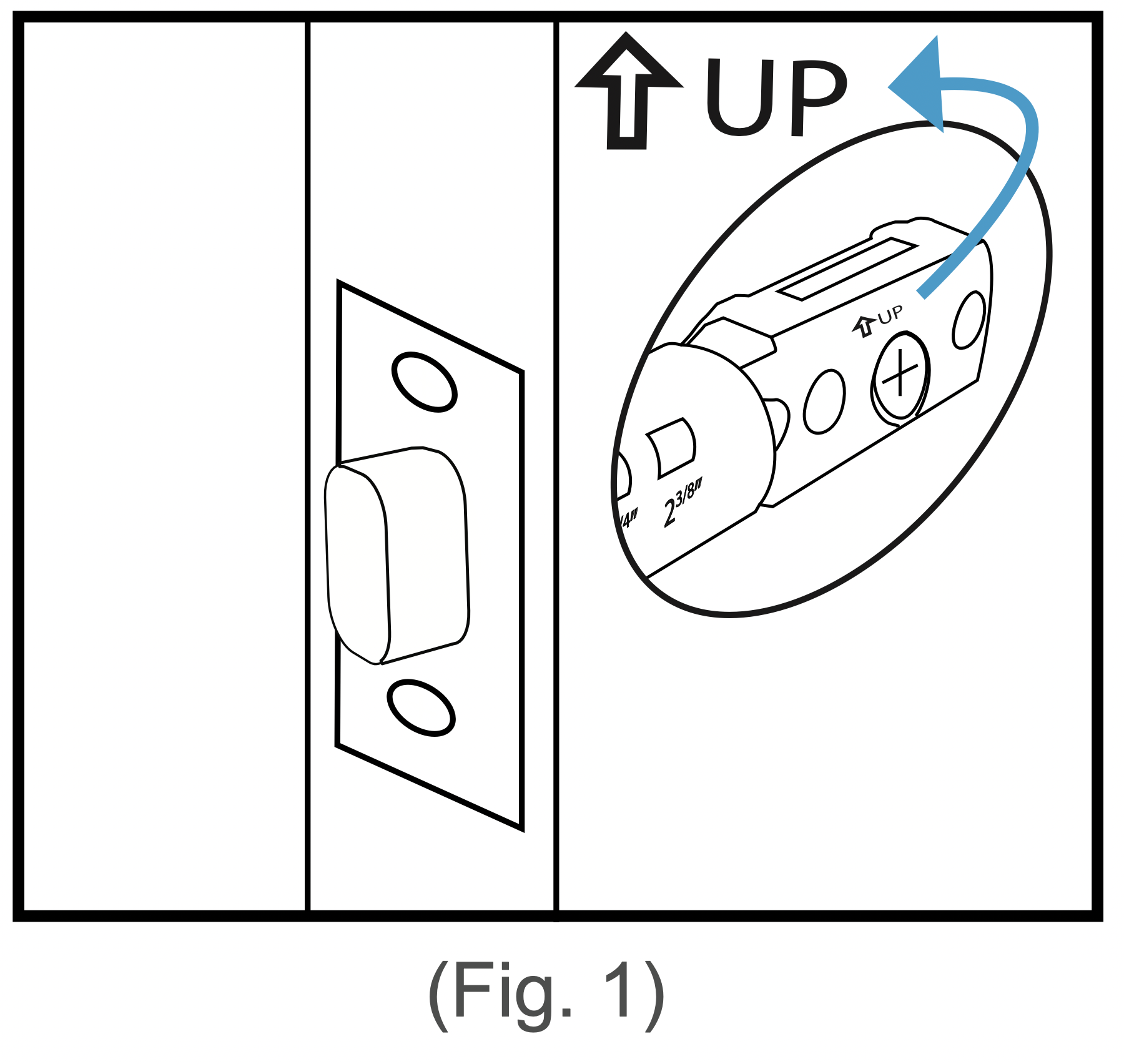
Step 1. Check the  icon on the latch and insert it into the hole. The latch’s plate should sit flush against the edge of the door. (Fig. 1) If there’s too much space behind the latch or if it’s sticking out of the door, the latch should be adjusted. If the latch needs adjusting, continue on to Step 2; otherwise, skip to Step 3.
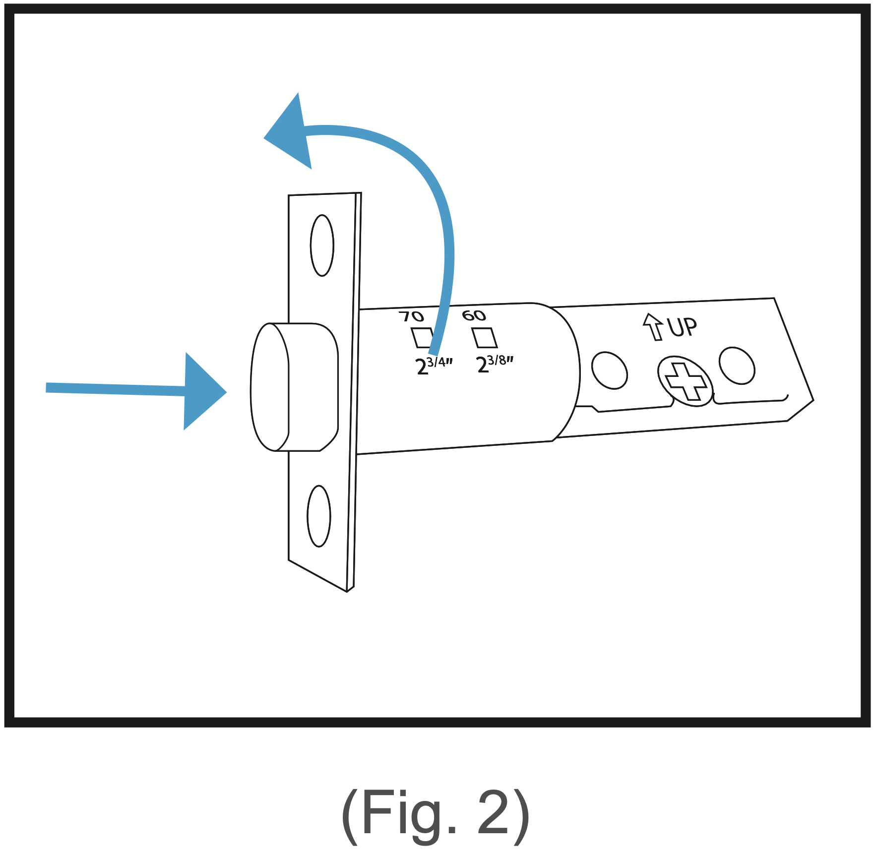
Step 2. Turn the latch and extend or retract it as needed. Make sure the metal peg pops into one of the two square holes in the side and the deadbolt is pushed all the way in while adjusting the latch’s length. (Fig. 2) Insert the latch back into the door.
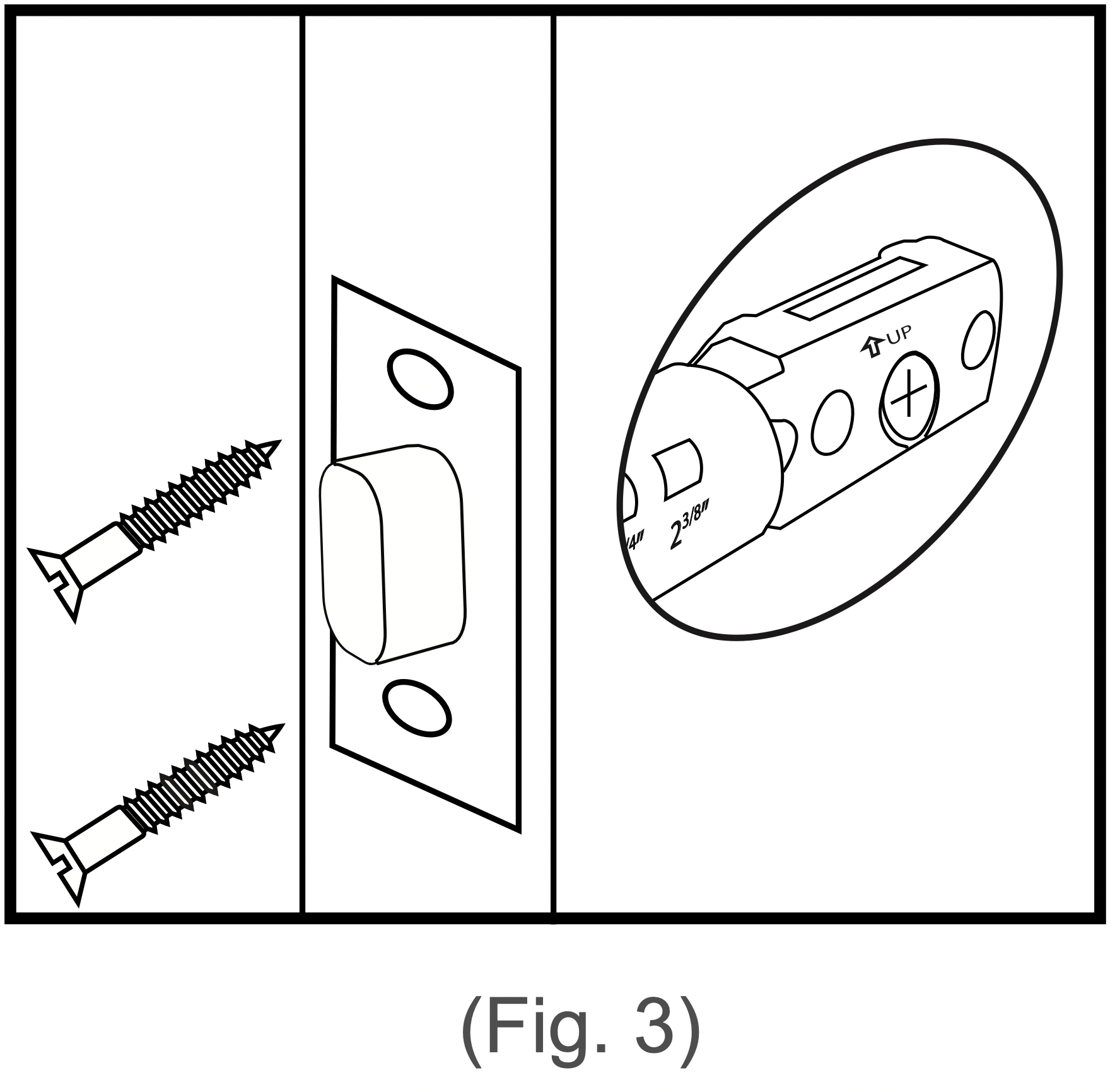
Step 3. Add 2x wood screws and use a screwdriver (not included) to secure them.(Fig.3)
Installing the Strike
In most cases, the existing strike plate and setup can be used. If you wish to use the one included with your lock, refer to the instructions for Part 3 on pages 15-16.
Adjusting for Door Orientation
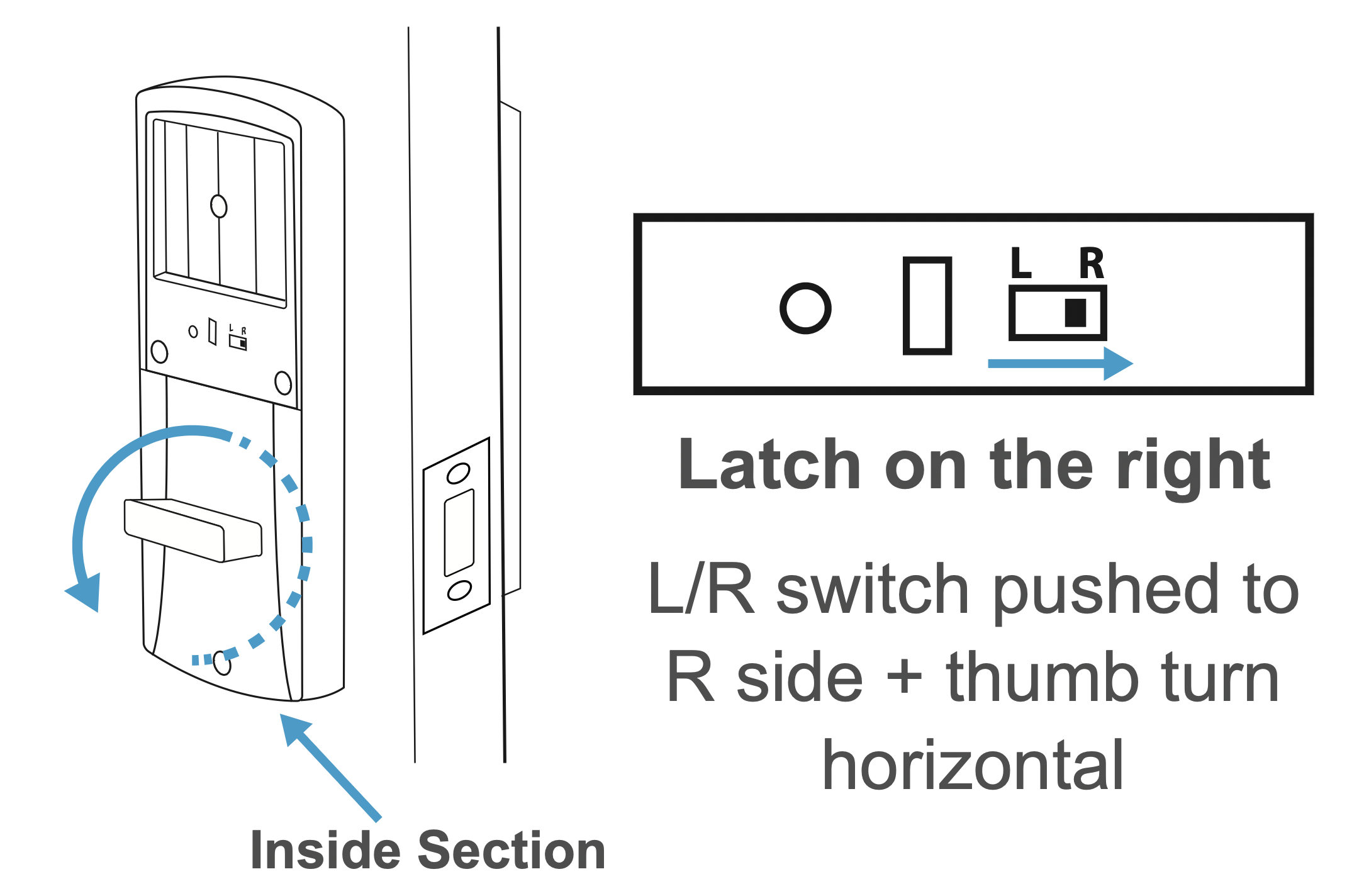
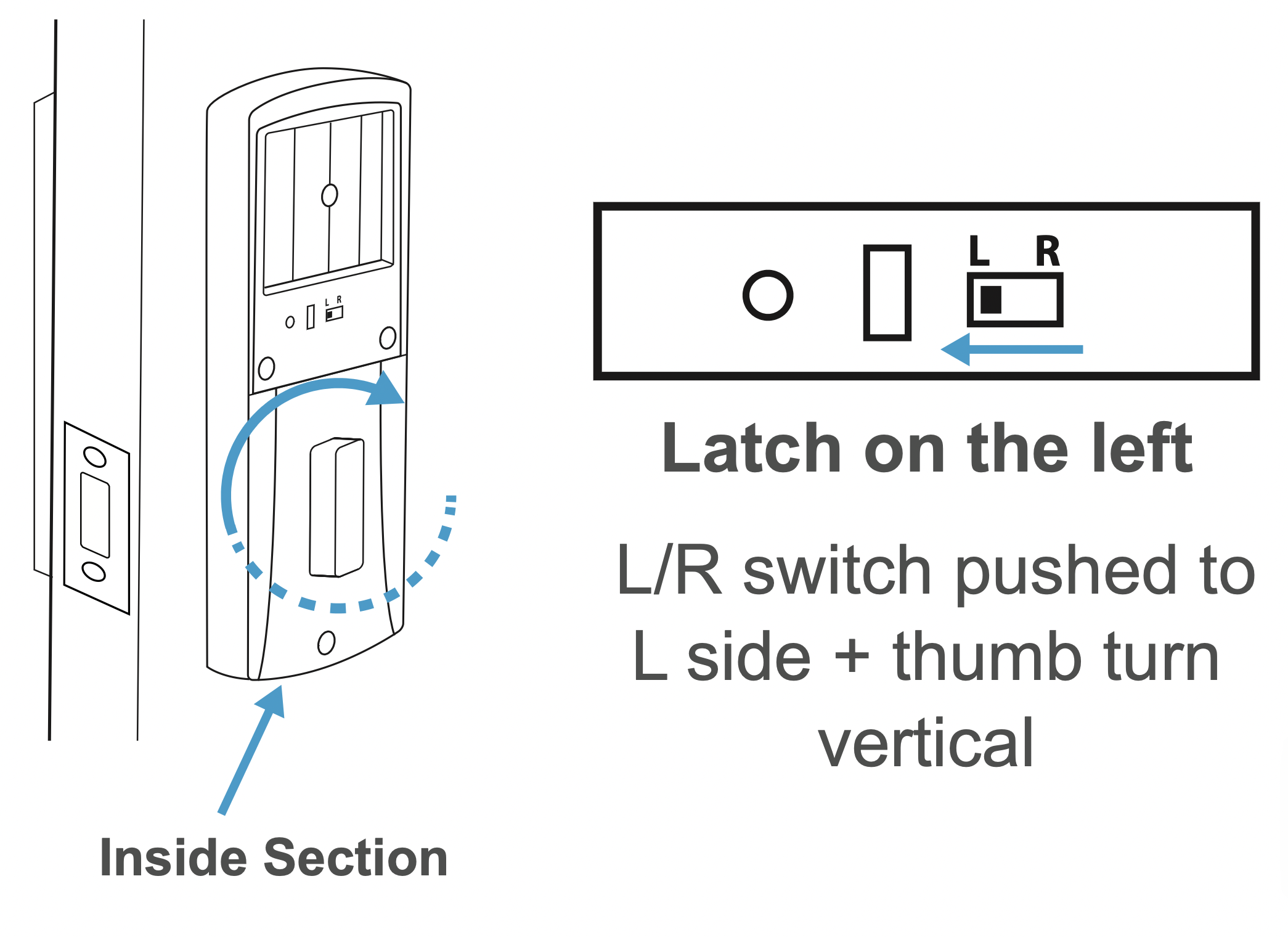
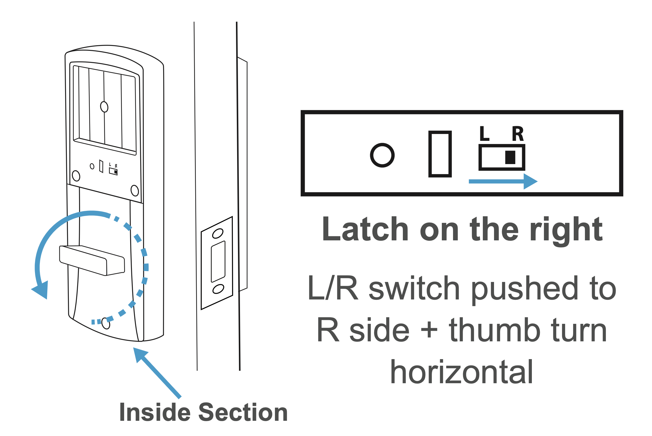
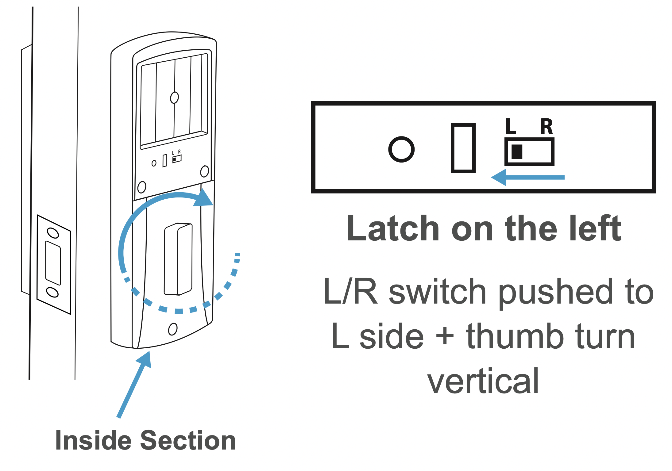
Step 1. With the door open, check it from the back and/or inside of the room. The lock’s parts should be oriented differently depending on whether the lock will be on the left side or right side of the door.
Step 2. Remove the battery cover from the inside section of the lock and adjust the L/R Switch and thumb turn as needed.
Main Installation
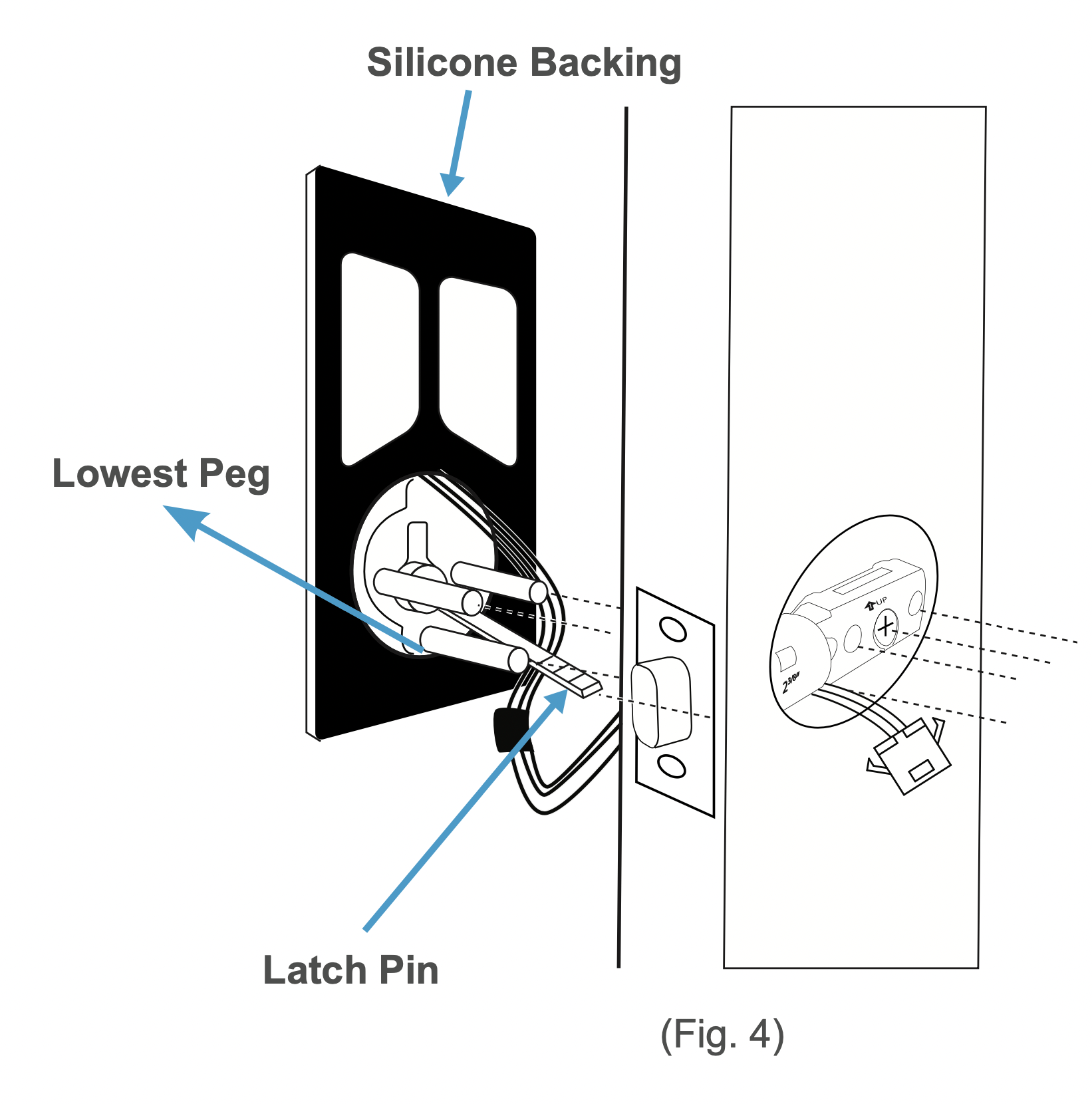
Step 1. Start with the outside section. Feed the power cables under the latch and thread the latch pin and two of the pegs through the latch. The third and lowest peg should be under the latch. If needed, have someone hold the door itself or hold the outside section flat against the front of the door.(Fig. 4)
Warning:
- Before threading the latch pin into the silver center part
 and make sure the key is turned so it can easily be removed from the keyhole. Make sure the latch pin is horizontal when inserting.
- It’s highly recommended to leave the door open and keep the keys in the lock during installation.
- Make sure the power cables are under the latch.
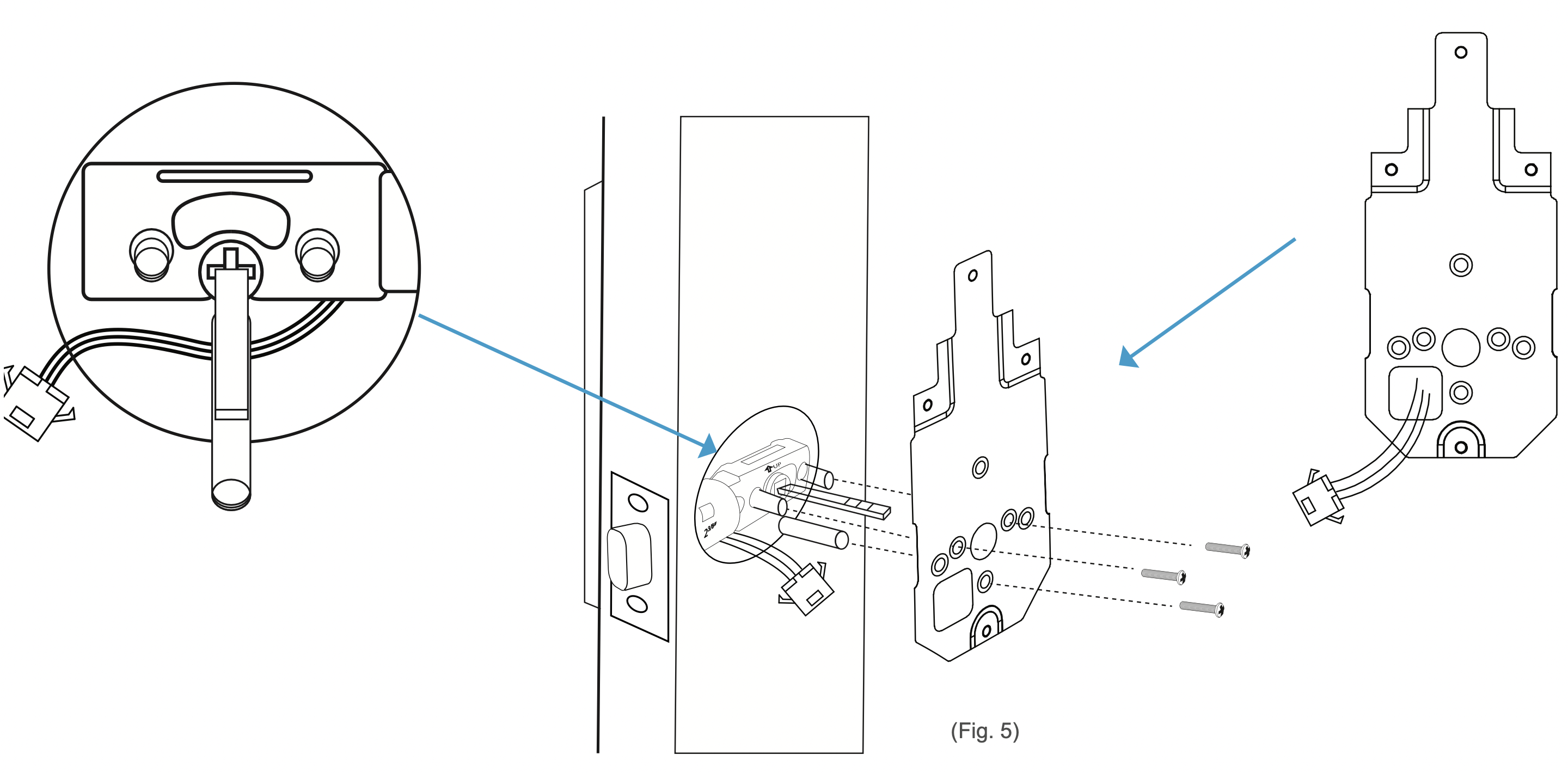
Step 2. Align the plate on the back of the door while making sure to thread the cables under the latch. Move the cables to the corner hole of the plate. Thread the latch pin through the larger hole and match up the pegs with the smaller surrounding holes. Use the 3x mounting screws to fasten the plate to the back of the door. Make sure all screws are tightened. (Fig. 5)
Warning:
- Check and adjust the plate or cables as needed to make sure the cables are tucked under the latch. Do NOT force the screw through the cables as this will damage the lock and/or make it unusable.
- Thread the cables through the opening in the corner of plate.
Step 3. Plug the cable into the inside section via the connectors. Make sure the lines and notches from each connector are on the same side. (Fig.6)

Step 5. Fit the inside section over the plate. Make sure to thread the latch pin into
Step 4. Check that the lock is set for the correct orientation. If needed, adjust the switch and thumb turn according to the orientation needed for your door. silver center part and tuck the cords away from the lowest screw hole. (Fig. 7) If needed, tuck the cables inside the door hole.
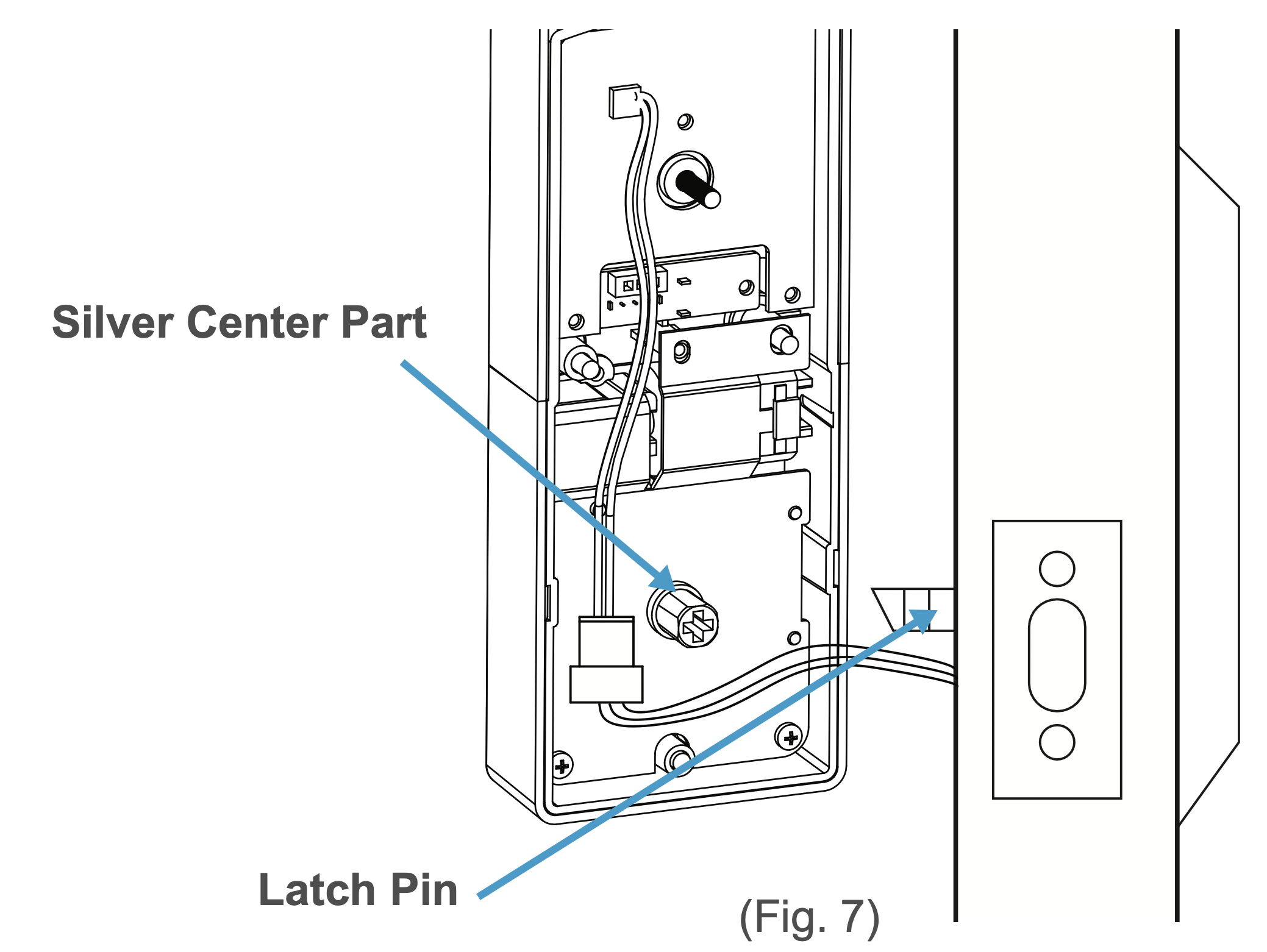
Warning: Before threading the latch pin into the silver center part  , make sure the key is turned so it can easily be removed from the keyhole.
Step 6. With the inside section flat against the back of the door, use the 4 x inside screws to fasten it to the back of the door.
Note the placements for the different sized screws. (Fig 8.) Make sure all screws are tightened.
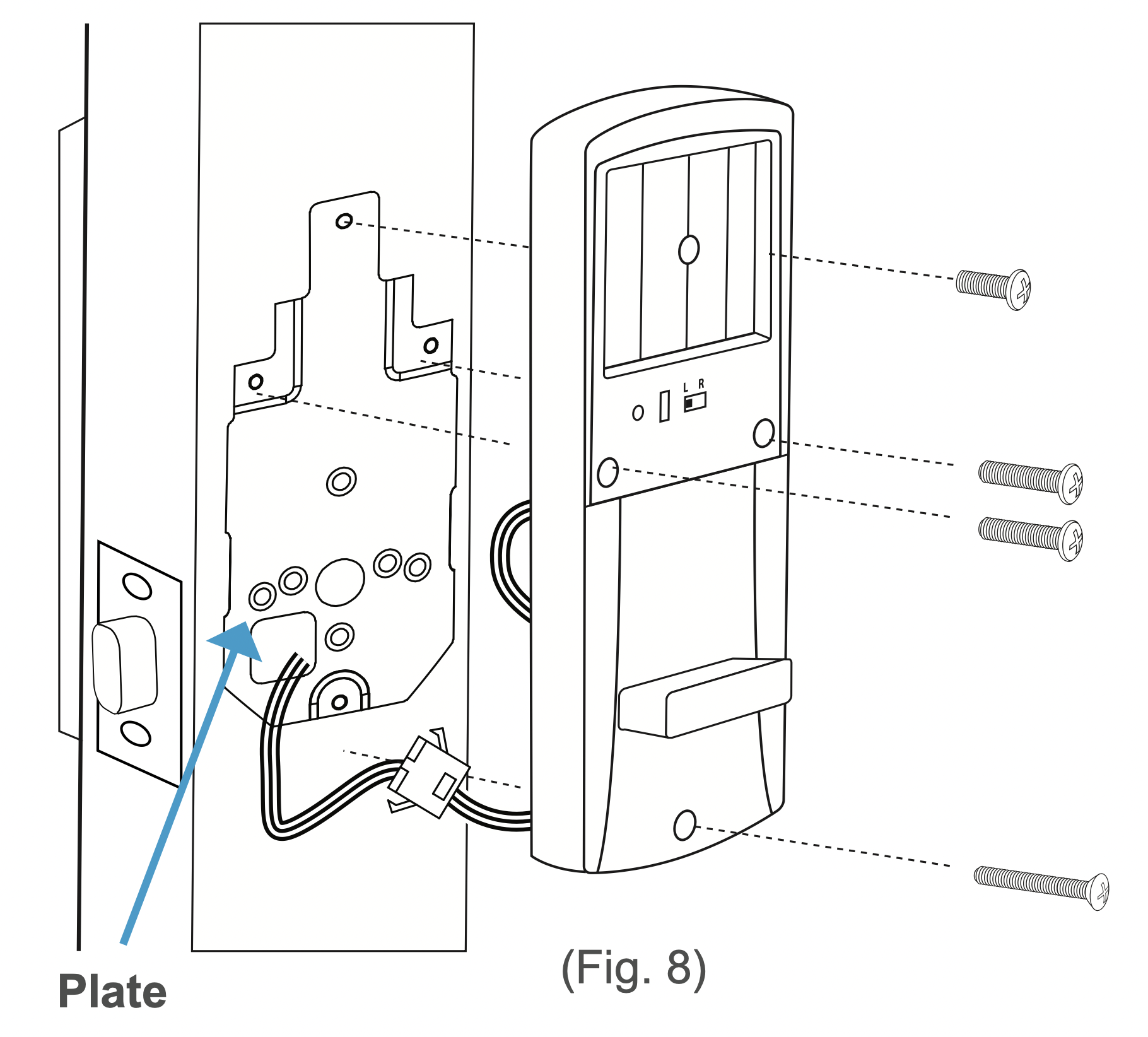
Warning: Check and adjust the cables as needed to make sure they are tucked away from any screw hole opening. Do NOT force the screw through the cables as this will damage the lock and/or make it unusable.
Step 7. Add batteries to the battery compartment, then slide the cover down over it. The lock should now be ready to use. It’s highly recommended to use the keys and default password to test the lock to make sure it works before closing the door. See Section 6 for information on the default admin password.
Installation (New)
Warning: This section details installation steps needed if you are installing the TL-201 on a door without a cutout. If you are using the TL-201 to replace an old lock or if your door otherwise already has a cutout, please go back to page 8.
Note:
- For easier installation, have another person help to hold the lock etc.
- For your convenience, installation instructions are broken into segments. Read and follow the instructions for both PreInstallation and Main Installation.
Pre-Installation
Making the Opening
Step 1. Using the provided template, mark the locations for the centers of the backset and the latch hole.
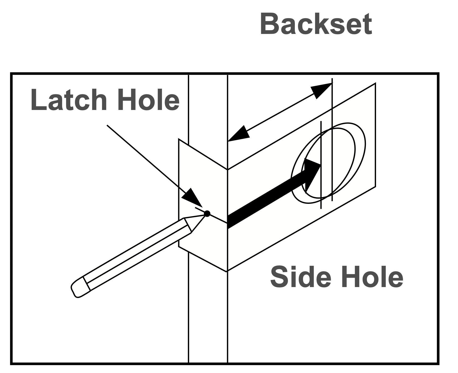
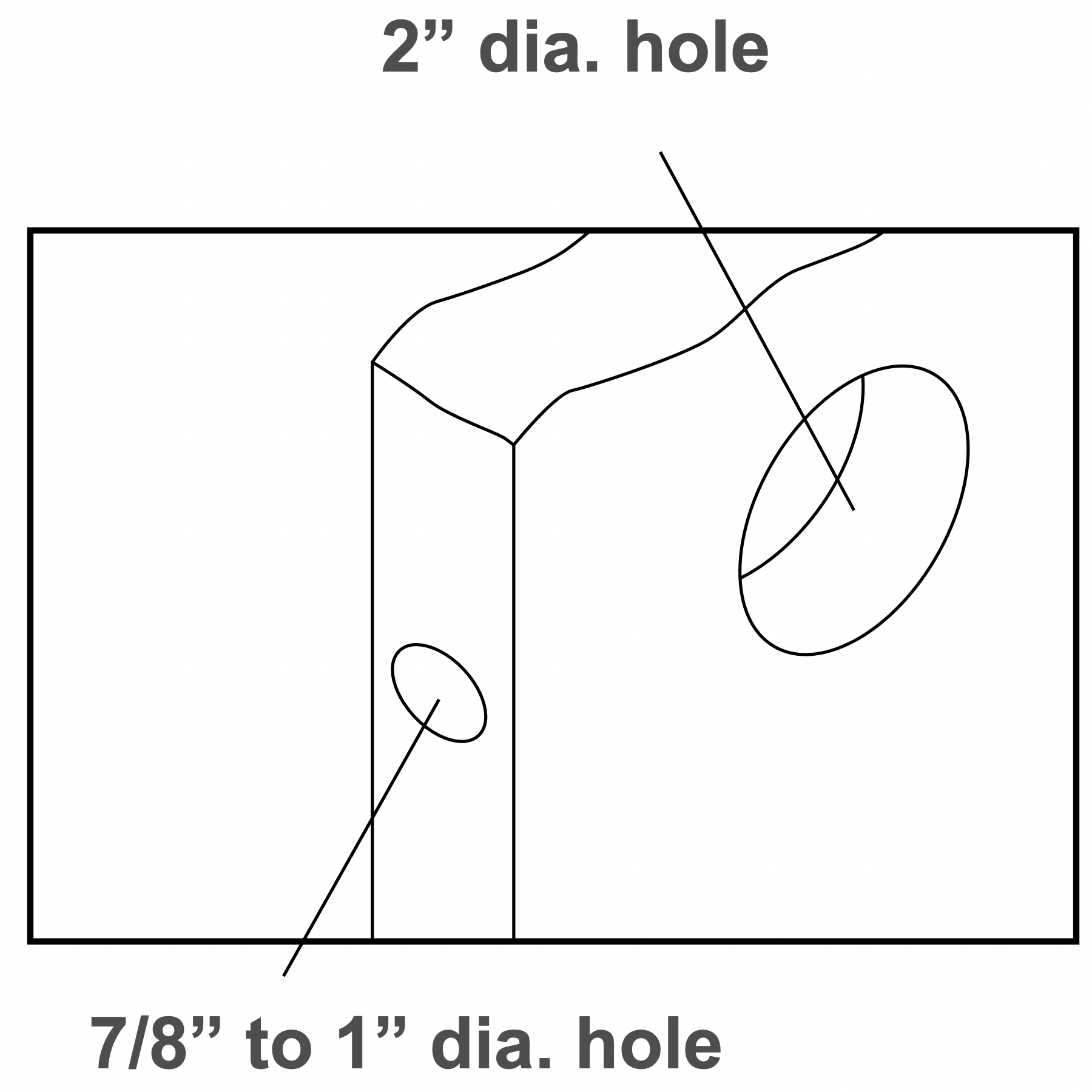
Step 2. Bore a 54mm (about 2” or 2 1/8”) hole on the door face, then drill a 25mm (about 1”) hole into the edge of the door so that it intersects with the larger hole.
Note:
- When drilling the 54mm (about 2” or 2 1/8”) hole, it’s recommended to drill from both sides of door to prevent splintering.
- It may be easier to drill the 54mm hole with a hole saw bit (not included).
- It may be easier to drill the 25mm hole with a hole saw bit (not included) or a 7/8” spade bit (not included). If using a spade bit, do not drill at high speeds as this may tear out extra wood and damage the door.
Installing the Latch
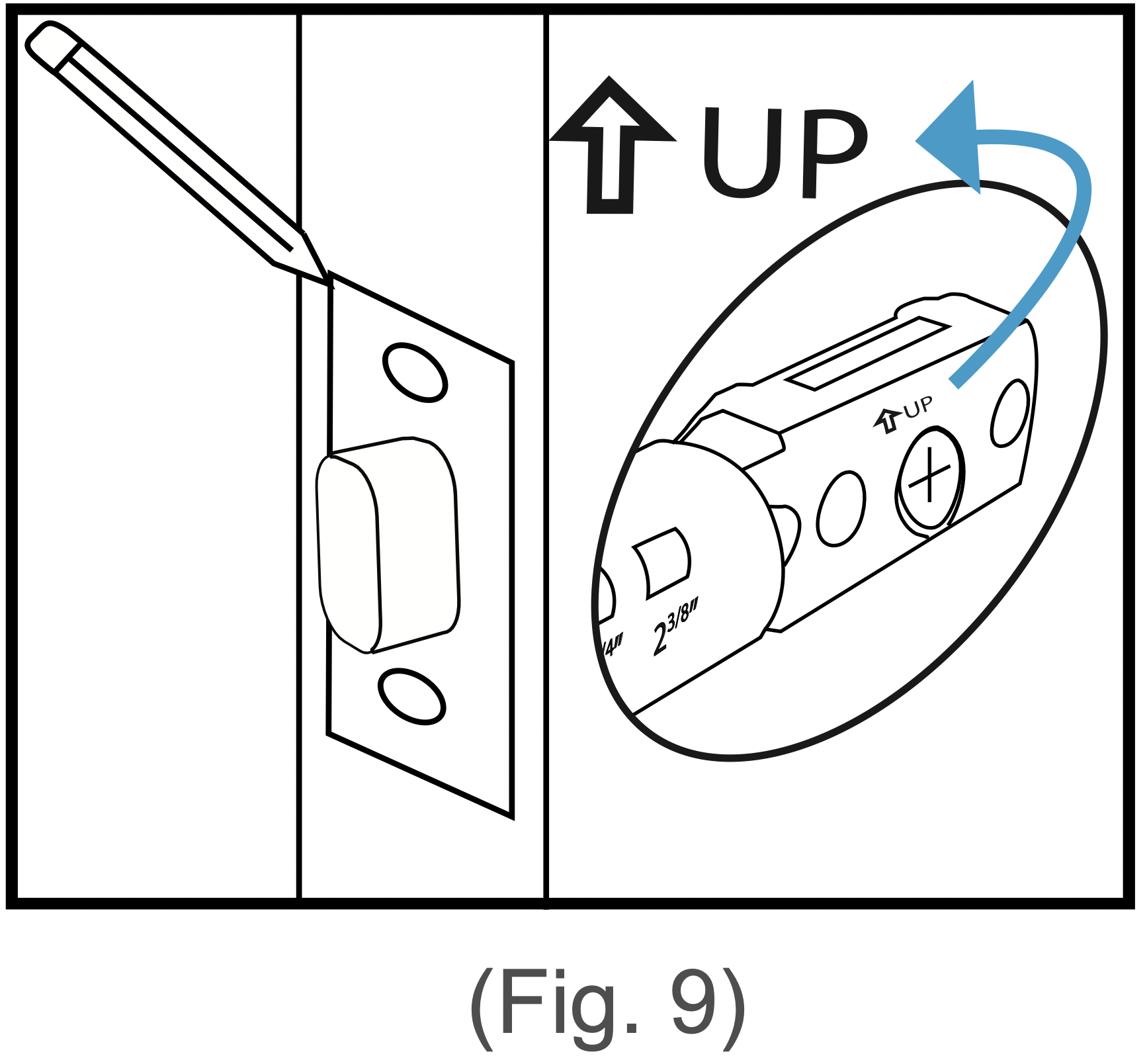
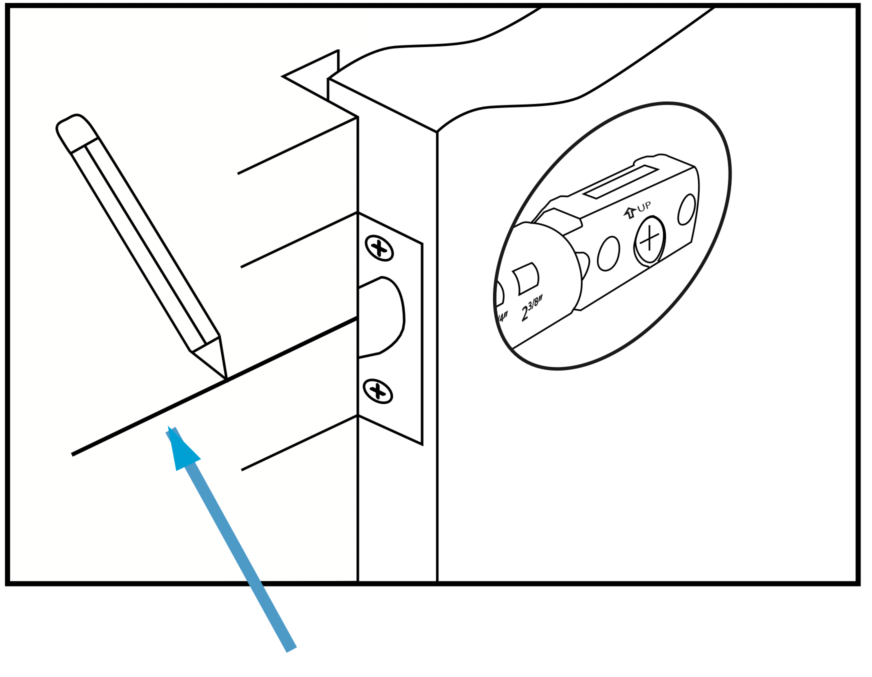
Step 1. Check the  icon on the latch and insert it into the hole. Using a pencil, mark a line around the edges of the latch to use as a guide. After marking each side, remove the latch. (Fig. 9).
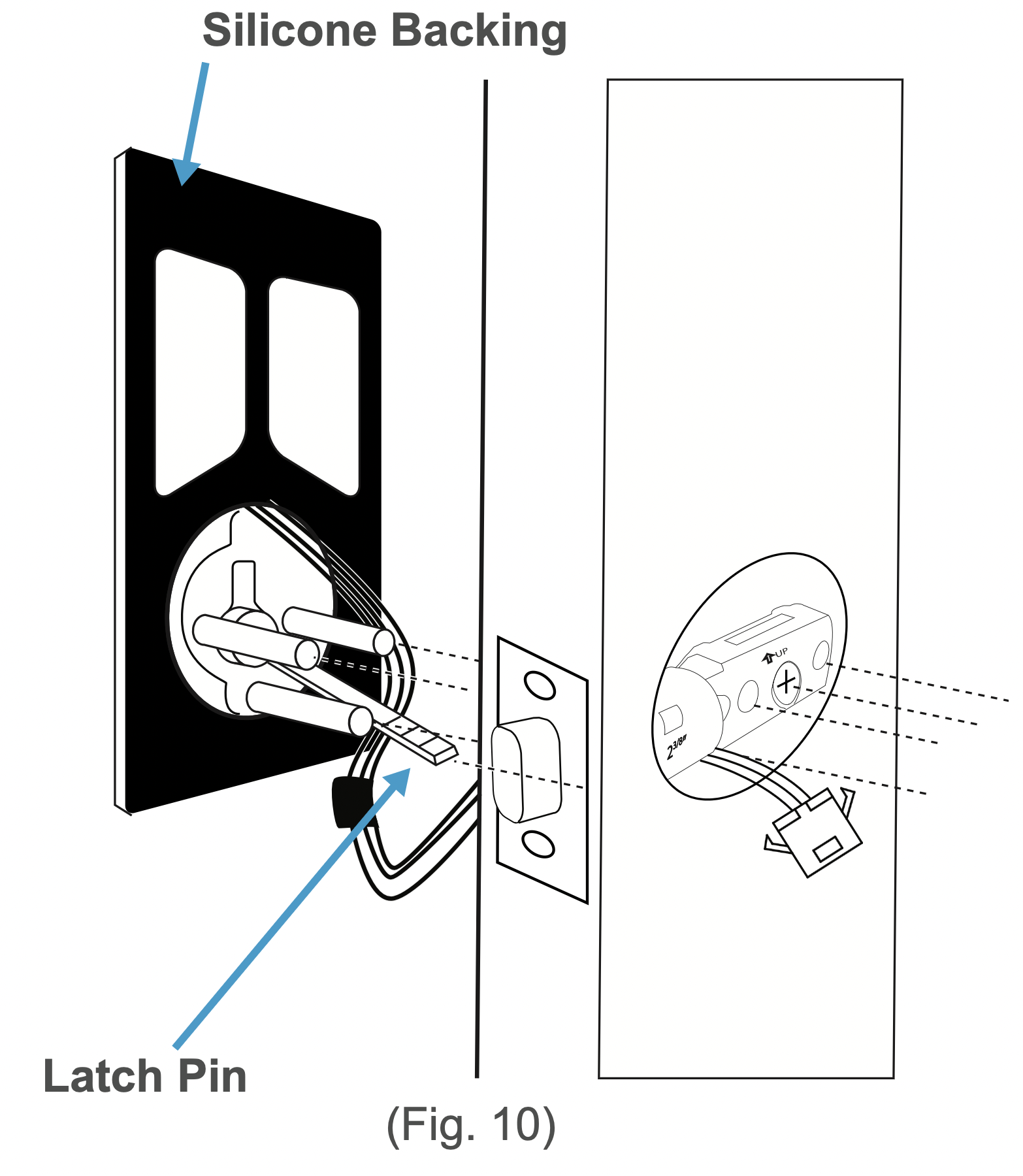
Step 2. Chisel about 3mm (0.1”) deep or until the latch plate sits flush with the door edge. (Fig. 10) (Fig. 9) (Fig. 10)
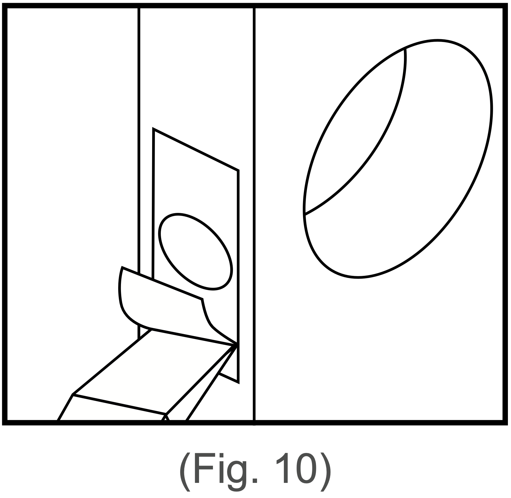
Note: During chiseling, it’s highly recommended to stop and reinsert the latch every once in a while to see if it sits flush. If not, chisel a little more and check again. Be careful not to chisel too deep otherwise the lock may not function correctly after installation.
Step 3. Insert the latch into the hole and check it. The latch’s plate should sit flush against the edge of the door. The latch should be adjusted if there’s too much space behind it or if it’s sticking out of the door. If the latch needs adjusting, move to Step 4. If it doesn’t need adjusting, skip to Step 5.
Step 4. Turn the latch and extend or retract it as needed. Make sure the metal peg pops into one of the two square holes in the side and the deadbolt is pushed all the way after adjusting the latch. Insert the latch back into the door.
Step 5. Add 2x wood screws and use a screwdriver (not included) to secure them.
Creating a Mortise & Installing the Strike
Step 1. Push the door until nearly closed and check where the latch’s bolt touches the frame.
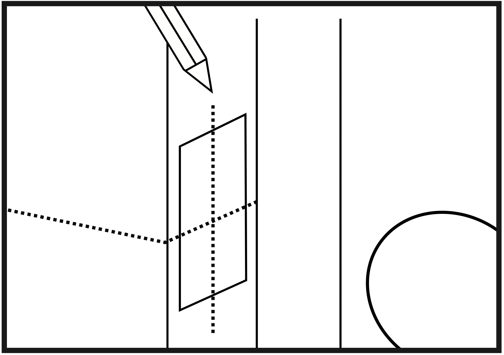
Step 2. Use a pencil to mark the horizontal center of the latch on the door frame.
Step 3. Open the door again and extend the line over the edge of the door and inside the frame.
Step 4. Measure the inside of the frame. Determine and mark the halfway point. From this point, use a ruler to draw a line straight down so that it intersects the existing line.
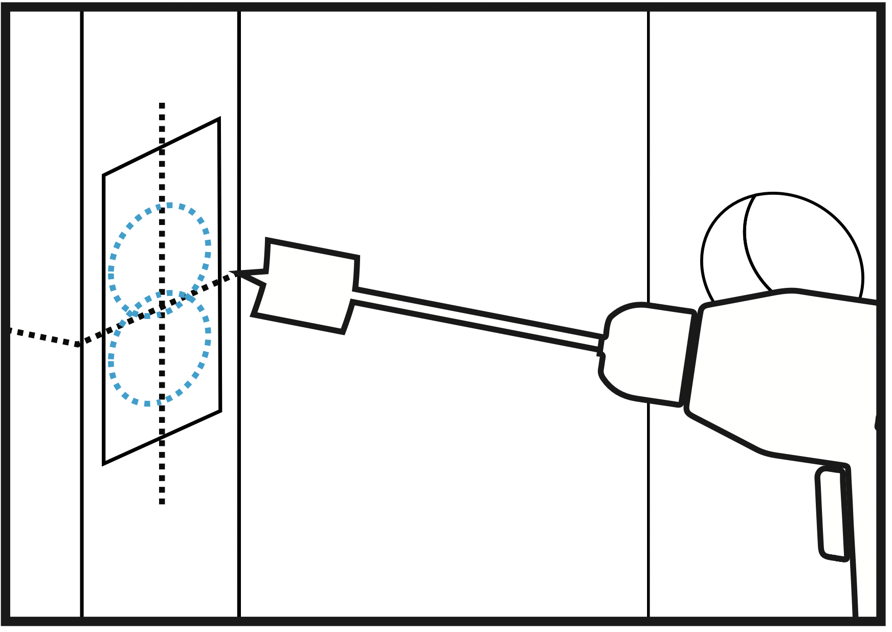
Step 5. Use a 7/8” (22.2mm) spade bit and a drill to make two partially overlapping holes approx. 0.6” (15mm) deep, centered above and below the center line. If needed, use the chisel to make the hollow (aka “mortise”) more square. Note: If you choose to use the strike box, you may need to chisel slightly deeper.
Note: If using a spade bit, do not drill at high speeds as this may tear out extra wood and damage the door or doorframe.
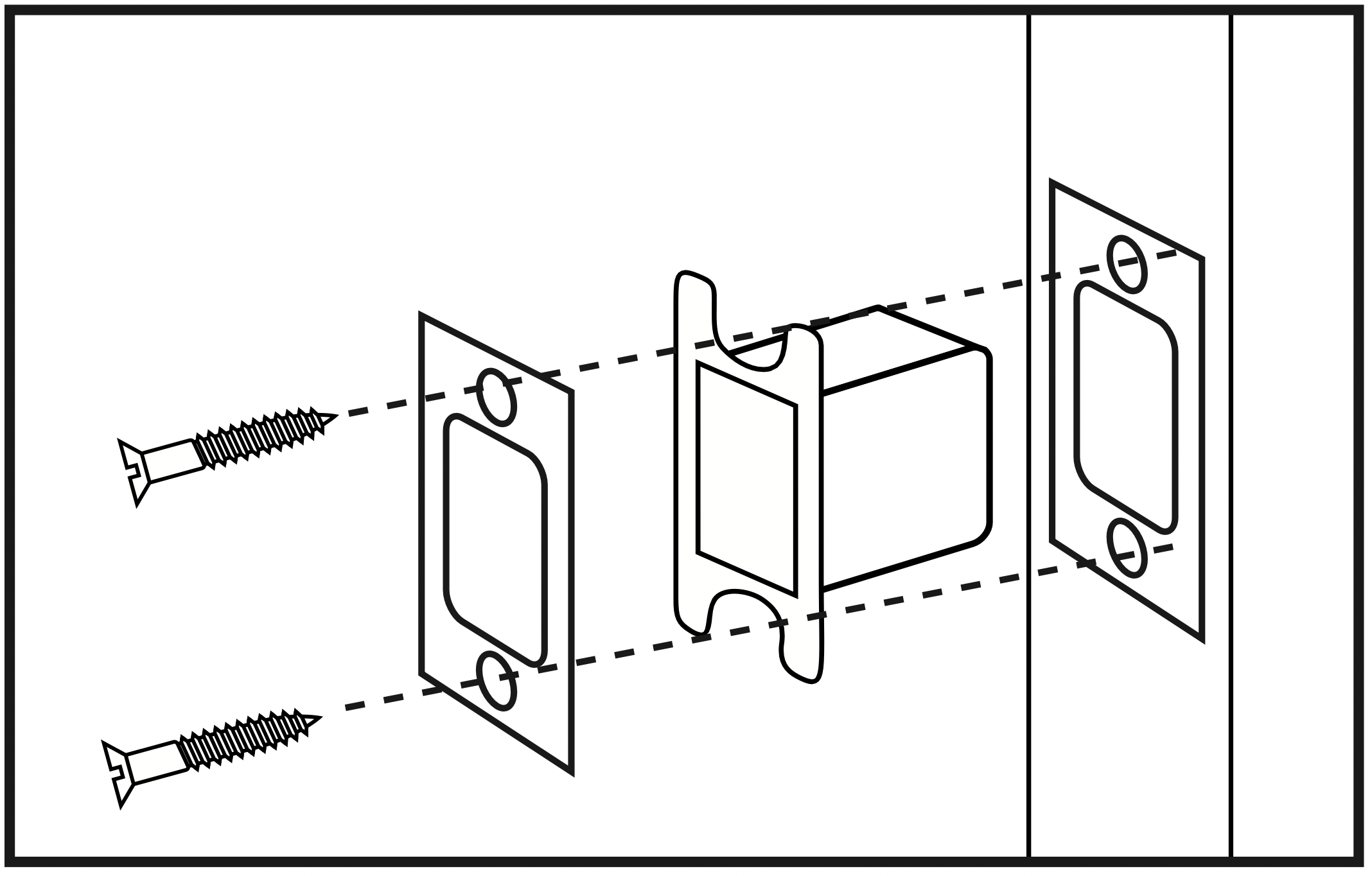
Step 6. Hold the strike plate over the mortise. Using a pencil, mark a line around the edges of plate to use as a guide. After marking at the straight edges of the plate, remove the plate.
Step 7. Chisel about 1.5mm deep or until the strike plate sits flush with the door frame. Note: If you choose to use the strike box, you may need to chisel slightly deeper.
Note: During chiseling, it’s highly recommended to stop and check that the strike plate sits flush in the doorframe over the strike box. If not, chisel a little more and check again. Be careful not to chisel too deep; otherwise, the lock may not function correctly after installation.
Step 8. Position the strike and strike box, then use a pencil to mark the center points of the screw openings in the strike plate. Set the strike and strike box aside and drill two small holes at each center point.
Step 9. Position the strike and strike box. Add the 2x remaining wood screws and use a screwdriver (not included) to secure them.
Adjusting for Door Orientation
Step 1. With the door open, check it from the back and/or inside of the room. The lock’s parts should be oriented differently depending on whether the lock will be on the left side or right side of the door.
Step 2. Remove the battery cover from the inside section of the lock and adjust the L/R Switch and thumb turn as needed.
Main Installation
Step 1. Start with the outside section. Feed the power cables under the latch and thread the latch pin and two of the pegs through the latch; the third and lowest peg should be under the latch. If needed, have someone hold the door itself or hold the outside section flat against the front of the door.(Fig. 10)
Note:
- Before threading the latch pin into the silver center part
 , make sure the key is turned so it can easily be removed from the keyhole. Make sure the latch pin is horizontal when inserting.
- It’s highly recommended to leave the door open and keep the keys in the lock during installation.
- Make sure the power cables are under the latch.
Step 2. Align the plate on the back of the door while making sure to thread the cables under the latch. Move the cables to the corner opening of the plate.
Thread the latch pin through the larger hole and match up the pegs with the smaller surrounding holes. Use the 3x mounting screws to fasten the plate to the back of the door. Make sure all screws are tightened. (Fig. 11)
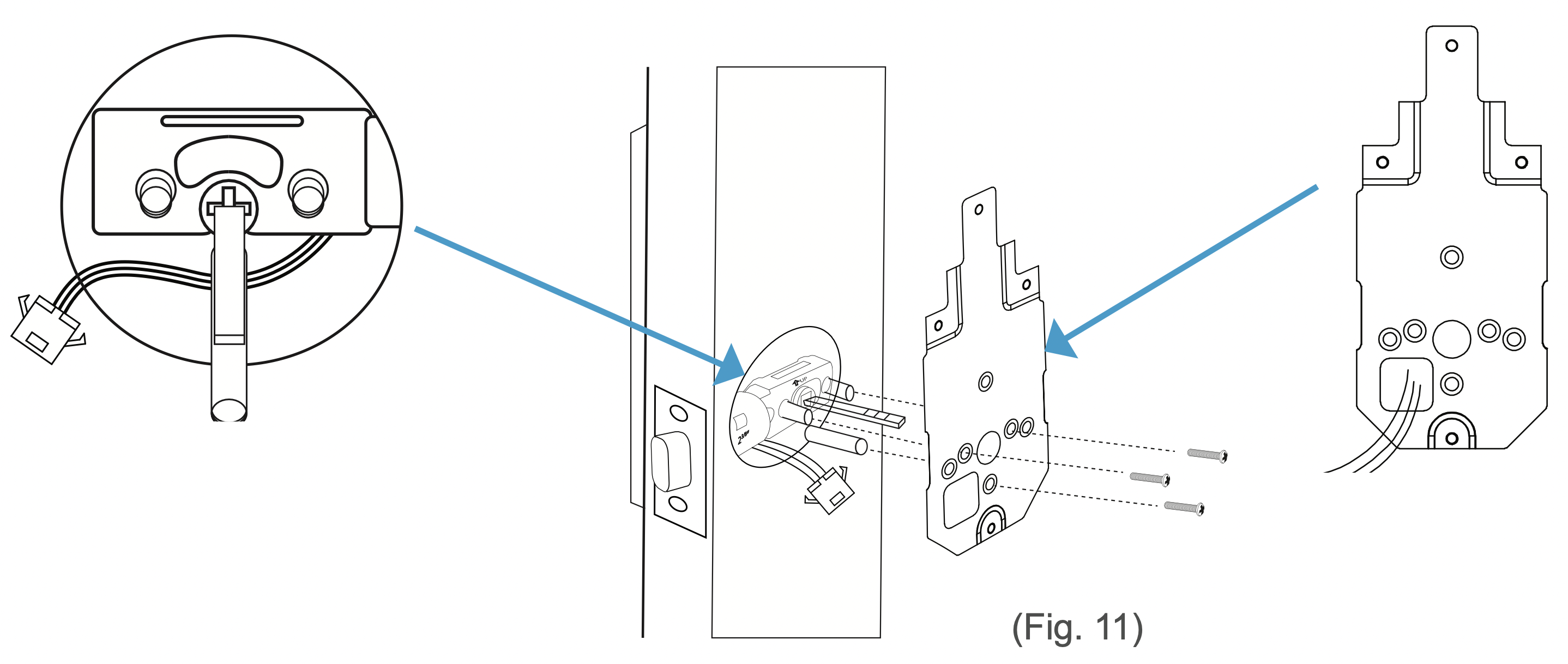
Warning: Check and adjust the plate or cables as needed to make sure the cables are tucked under the latch. Do NOT force the screw through the cables as this will damage the lock and/or make it unusable.
Step 3. Connect the cables to the connectors. Make sure the lines and notches from each connector are on the same side.

Step 4. Check that the lock is set for the correct orientation. If needed, adjust the switch and thumb turn according to the orientation needed for your door. Refer to the images on page 16.
Step 5. Fit the inside section over the plate. Make sure to thread the latch pin into silver center part and tuck the cords away from the lowest screw hole. (Fig. 12) If needed, tuck the cables inside the door hole.
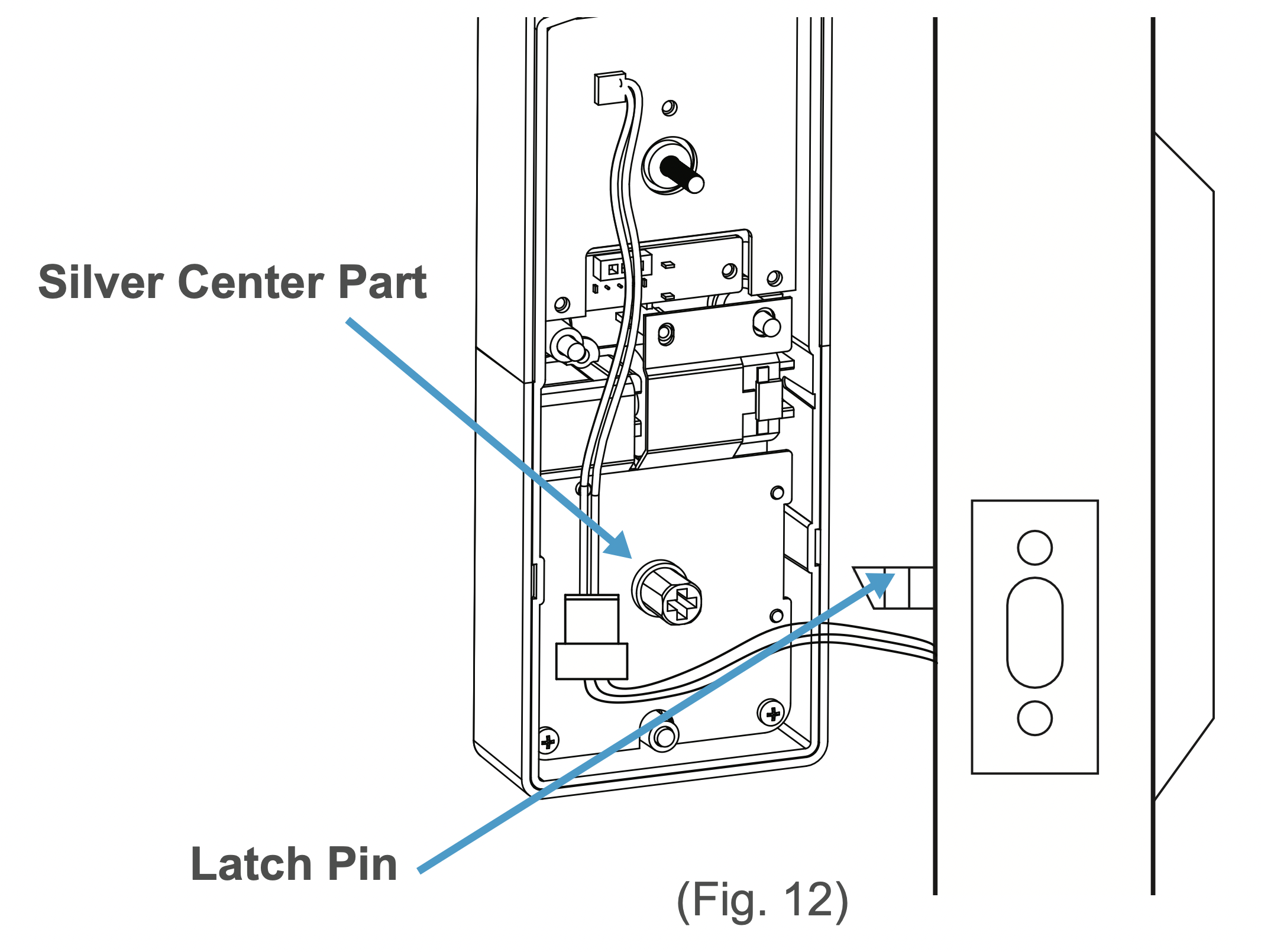
Warning: Before threading the latch pin into the silver center part , make sure the key is turned so it can easily be removed from the keyhole.
Step 6. With the inside section flat against the back of the door, use the 4x inside screws to fasten it to the back of the door.
Note the placements for the different sized screws. (Fig. 13) Make sure all screws are tightened.
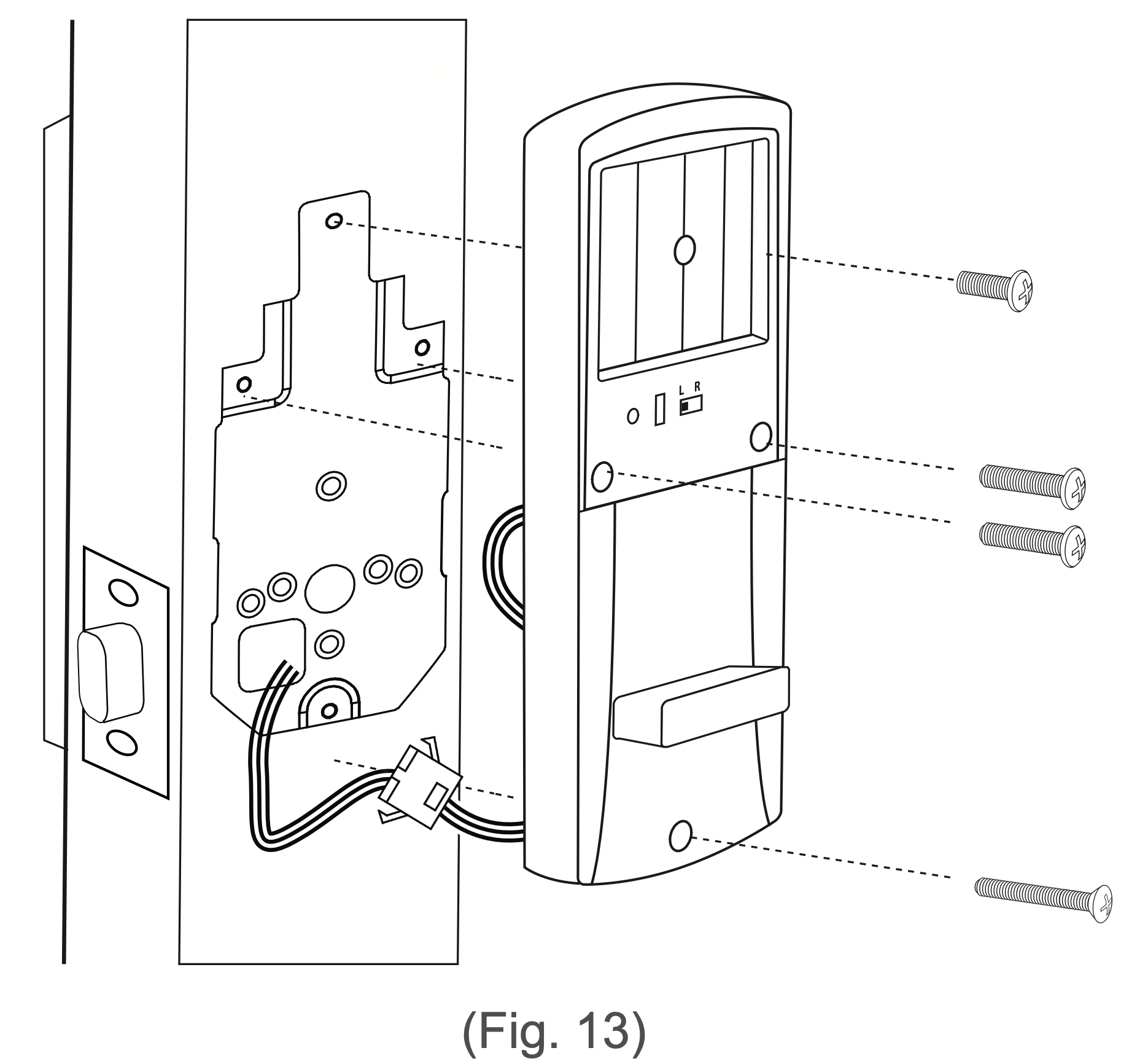
Warning: Check and adjust the cables as needed to make sure they are tucked away from any screw hole opening. Do NOT force the screw through the cables as this will damage the lock and/or make it unusable.
Step 7. Add batteries to the battery compartment, then slide the cover down over it. The lock should now be ready to use.
It’s highly recommended to use the keys and default password to test the lock to make sure it works before closing the door. See Section 6 for information on the default admin password.
Using the Lock
In general, there are two ways to unlock your door: using keys or using the keypad to enter the password, then pressing the  button. The lock will engage.
Caution: Regardless of unlock method, the TL-201 will not lock again on its own. To lock the door, close it, wait for the keypad light turns off, then press the  button. The lock will engage and lock the door. If the keypad lights up, press the
  button twice to lock the door. (Pressing the lock button once will turn off the backlight. Pressing the lock button twice engages the lock.)
Using the Admin Password
Enter the Admin Password on keypad, and then press the  button. The lock will engage allowing you to open the door. Note, the Admin Password must be changed from the default password. See Section 6.
Using a User Password
Enter the password received from the admin, and then press the  button. The lock will engage allowing you to open the door.
Note:
- The TL-201 also features a Mute Function. See Section 7.
- If a password has been entered wrong 5x in a row, the lock will go into a 15-minute period of inactivity where it cannot be used. This is a security feature designed to prevent unwanted parties from using the lock.
Keypad Passwords
Changing the Admin Password
Caution:
- Admin passwords must be 4~6 digits long.
- The default Admin Password is ‘123456’.
- For security, it is highly recommended that you change the Admin Password from the default.
Step 1. First, make sure the TL-201 is fully unlocked. Then, use the keypad to enter the default (‘123456’) or current Admin Password, then press the  button.
Step 2. Wait for the backlight to flash red and then blue again. Quickly enter ‘1’ and press the  button before the light turns off.
Step 3. Enter the new Admin Password, and then press the  button. The lock should beep to confirm the change. If desired, test the new password afterwards.
Note: The new password must be entered while the blue backlight is on. If it goes out, begin again at Step 1.
Adding User Passwords
Note:
- The admin must create passwords for users.
- User passwords must be 4~6 digits long.
- Do not use the same combination for admin and user passwords.
Step 1. First, make sure the TL-201 is fully unlocked. Use the keypad to enter the current Admin Password, then press the  button.
Step 2. Wait for the backlight to flash red and then blue again. Quickly enter ‘2’ and press the  button before the light turns off.
Step 3. Enter the new 4~6 digit user password, and then press the  button. The lock will beep to confirm the password was added.
Step 4. Repeat step 3 with different passwords to add multiple user passwords (up to 20 at a time). Note: all passwords must be entered and while the backlight remains on.
Step 5. Passwords can now be given to users as needed.
Changing User Passwords
Note:
- To change user passwords, you must use the current user passwords to open the lock first.
- User passwords must be 4~6 digits long.
Step 1. Make the TL-201 is fully unlocked. Use the keypad to enter the current User Password, then press the  button.
Step 2. Wait for the backlight to flash red and then blue again. Quickly enter ‘3’ and press the  button before the light turns off.
Step 3. Enter the new 4~6 digit user password, and then press the  button. The lock will beep to confirm the change. If desired, test the new password afterwards.
Deleting all User Passwords
First, make sure the TL-201 is fully unlocked. Then, use the keypad to enter the current Admin Password, then press  the button. The lock should beep and the backlight should turn blue again. Quickly enter ‘4’ and press the
  button before the light turns off. All user passwords will then be erased.
Disguising Your Password
This function is an added security feature aimed at preventing password theft. With Passcode Disguise, you may enter 12 digits into the keypad. As long as the correct password sequence is entered, regardless of how many digits were entered before or after, the TL201 will unlock.
For example, if your user password is “0808“, you can enter digits before and/or after you enter “0808” to confuse any unwanted party who may be watching. In this case, “113540808”, “110808”, “108081”, and “208082256977” and so on will all successfully open the door while concealing your password.
Using the Mute Function
Caution: USE WITH CAUTION. Remember to turn off the function when it is no longer needed. Do not leave this function on for extended periods of time.
Muting/Un-muting
Step 1. First, make sure the TL-201 is fully unlocked. Then enter the current Admin Password and press the  button.
Step 2. Wait for the backlight to flash red and then blue. Quickly enter ‘8’ and press the button before the light turns off.
Resetting the Lock
Caution:
- Resets cannot be reversed.
- Performing a reset will delete all passwords including the Admin Password.
- Once all passwords are erased, only the default Admin Password can open the lock.
- After a reset:
- Admin Password will return to its default ‘123456’.
- Choose a new Admin Password immediately. See Section 6.
Option 1
Step 1. Remove the cover from the battery compartment at the back of the lock.
Step 2. Press and hold the reset button for at least three seconds.
Option 2
Step 1. First, make sure the TL-201 is fully unlocked. Use the keypad to enter the Admin Password, then enter .
Step 2. Wait for the backlight to flash red and then blue. Enter ‘9’ and then press before the blue back light turns off.
Note: The TL201 will automatically reset anytime the lock is removed and/or the any internal cables are disconnected and reconnected.
Maintenance
Proper cleaning and maintenance of your lock ensures it will continue to work as it should.
- The keypad is made of acrylic. Use water and soft, non-abrasive cloth when cleaning.
- If a mess cannot be cleaned with water, apply a gentle cleaner to the cloth and clean.
- Do not apply any cleaner or detergent directly to any part of the lock.
- After cleaning with any cleaner, apply clean water to a new, non-abrasive cloth, wipe the lock clean, and dry so as not to leave residue on the lock.
- Do not let water and liquids get into the lock’s electric parts or battery compartment.
Troubleshooting
| Problem |
Possible Cause
|
Solution(s) |
|
Why can’t I open the door?
|
Too much time has passed.
|
Turn the handle to open the door while the lock’s back light is still on.
|
|
Your access has been restricted.
|
If you received a key from the lock’s admin, your access may be restricted to certain times of the day etc. Check with your admin regarding these details.
|
|
Why does the lock jam? / The door doesn’t close.
|
The latch size is wrong.
|
Disassemble the lock and check the latch assembly. If retrofitting, check the latch length and adjust as needed. If installed on a new door, adjust the latch and/or, drill into the door to fit the latch as needed.
|
|
The strike plate and latch aren’t correctly aligned.
|
Open the door and check the alignment of both the latch and the strike plate. Adjust as needed.
|
|
The lock doesn’t work.
|
The lock isn’t receiving power.
|
Ensure the batteries are properly installed. Remove and reinstallif needed.
|
|
The batteries are entirely dead and/or were not replaced in a timely manner.
|
Replace the batteries.
|
|
Use the micro USB port to power the lock so that the door opens. Replace the batteries.
|
|
I entered the password wrong (at least 5x).
|
If a password has been entered wrong 5x in a row, regardless of the entry method, the lock will go into a 15-minute period of in activity where it can not be used. This is a security feature designed to prevent unwanted parties from using the lock.
|
Wait 15 minutes and try again.
|
|
Why is the lock beeping multiple times?
|
|
I forgot my codes.
|
The codes were not properly recorded.
|
Perform a reset in order to erase all passwords. In order toperform a reset, you must have access to the back of the door. Once a reset is performed, record the passwords in memory or a secure location.
|