In order to continue serving our customers
and providing the best products, our
product information including our user
manuals may receive updates from time
to time. Please check our website for the
latest user manuals and product materials.
Version 1.0 7/26/19

www.turbolock.com
Customer Service: 855-850-8031

Section 1
Information & Safety Warnings 4
1.1 Introduction 4
1.2 Safety Warnings 4
1.3 End-of-Life Disposal 5
Section 2
Package Contents & Overview 6
2.1 Contents 6
2.2 Overview 6
2.3 Battery Information 7
2.4 Usage Overview 7
Section 3
Installation (Retrot) 8
3.1 Pre-Installation 8
3.2 Main Installation 10
Section 4
Installation (New) 12
4.1 Pre-Installation 12
4.2 Main Installation 15
Section 5
Using the Lock 18
Section 6
Keypad Passcodes 18
6.1 Changing the Admin Passcode 18
6.2 Adding Keypad Passcodes 19
6.3 Delete a Single Passcode 20
6.4 Delete All Passcodes 20
6.5 Passcode Disguise 20
Section 7
Using the Mute Function 21
7.1 Activating Mute Mode 21
7.2 Deactivating Mute Mode 21
Section 8
The TurboLock Plus App 21
8.1 App Installation 22
8.2 Pairing 22
8.3 App Usage 23
8.4 Generating Keypad Passcodes 24
8.5 Managing User Passcodes (E-Keys)
25
Section 9
Resetting the Lock 26
Section 10
Specications 27
Section 11
Maintenance 28
Section 12
Troubleshooting 28
Section 13
Warranty 31
13.1 Violation 31
13.2 Information 31
Table of Contents

4 TURBOLOCK TL115
Section 1
Information & Safety Warnings
1.1 Introduction
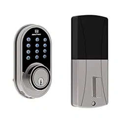
This user manual will guide you through the functions and usage of your TURBOLOCK TL115 Bluetooth-enabled Smartlock. It is
important that you follow all instructions and regard all notes that appear throughout this manual. Consult this manual before you
attempt to use your lock. If you have questions not answered by this manual or are in need of repair or non-routine service, contact
customer service at 1-855-850-8031. Before contacting customer service, please have your purchase information ready as this may
be needed during the call. Please record this information below:
Date of Purchase:
Place of Purchase:
1.2 Safety Warnings
When reading this manual, note these icons:
Notes with this icon MUST be read, understood, and obeyed to prevent injury or damage.
Notes with this icon include relevant information.
General Precautions
• The lock shall only be used as described in this manual.
• Verify that all parts of the lock are accounted for. If any part is missing, contact customer service.
• If the battery compartment or surrounding parts are damaged, do not use the lock.
• Use only 9V alkaline batteries (one is included).
• Never insert objects into the lock other than batteries as described in this manual.
• The lock is not a toy. Do not leave children unsupervised around the lock.

TURBOLOCK TL115 5
• Use only the parts included in the original packaging or received from TURBOLOCK.
• Verify all surfaces are at and level before beginning installation. Installation on doors or surfaces with any type of
deformity such as gaps or warping may cause the lock to malfunction or fail to operate entirely.
• Expected use is for standard doors made for buildings within the U.S.
• New batteries on average can deliver up to one full year of use before replacement is needed. Battery life varies by
usage.
• Replace the batteries after receiving the lock’s low battery notication.
• Never apply any cleaner directly to any part of the lock. Only use clean (or puried) water and mild cleaner on a soft,
non-abrasive cloth when cleaning.
• Potential Shock Warning: Do not allow water and/or liquids to get into the lock’s electric parts.
• Never submerge the lock or any of the lock’s components.
• Hanging objects on the lock is not recommended.
• The lock may be used with the TurboLock Plus app. The lock will function without the app but full functionality may
only be achieved when the app is used.
1.3 End-of-Life Disposal
This product must not be disposed of by incineration, landlling, or mixing with household trash. Improper disposal of the
battery contained within this product may result in the battery heating up, rupturing, or igniting which may cause serious injury.
The substances contained inside the battery present chemical risks to the environment. The recommended disposal for any
TURBOLOCK TL115 at its end-of-life is to dispose of the entire unit at or through an e-waste recycling center, program, or facility.
Local regulations and laws pertaining to the recycling and disposal of certain types of batteries and/or products containing them
will vary according to country, state, and local governments. Please check laws and regulations corresponding to where you live in
order to properly dispose of the battery and/or unit. It is the user’s responsibility to dispose of their waste equipment properly with
accordance with local regulations and laws.
For additional information about where you should drop o your batteries or electronic waste, please contact your local or regional
waste-management oce, your household waste disposal service, or your point-of-sale.
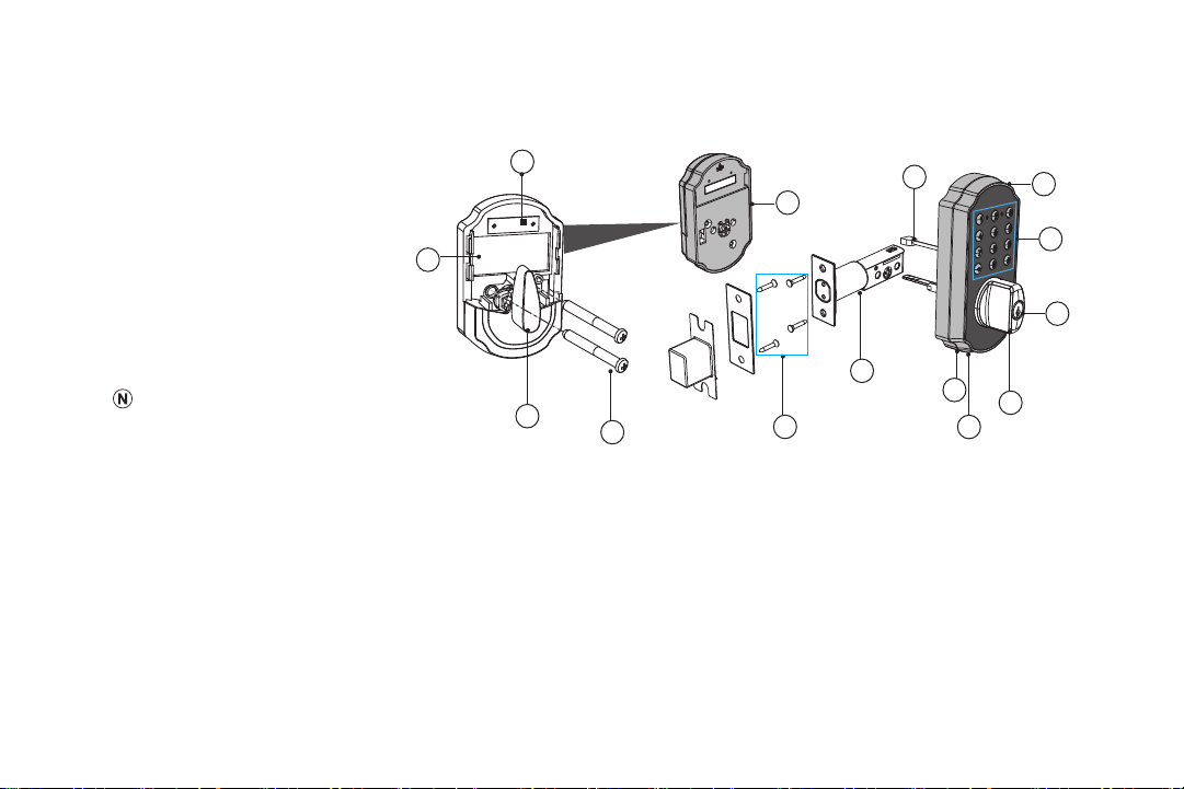
1: Battery Compartment
2: Inside Knob
3: Mounting Screws
4: Wood Screws
5: Latch Assembly
6: Micro-USB Charging Port
7: Speaker
8: Outside Knob
9: Key Hole
10: Keypad
11: Outside Assembly
12: Power Cable
13: Inside Assembly
14: Reset Button
6 TURBOLOCK TL115
Section 2
Package Contents & Overview
2.1 Contents
TL115 Bluetooth-enabled Smartlock x 1
Outside Knob x 1
Inside Knob x 1
Latch Assembly x 1
Wood Screws x 6
Mounting Screws x 2
Keys x 3
- Mounting screws may already be
inside the lock upon opening.
- Requires 9V alkaline batteries (included).
2.2 Overview
2
1
4
3
5
13
7
8
6
14
9
10
11
12

TURBOLOCK TL115 7
2.3 Battery Information
The lock requires 9V alkaline battery. New battery should be installed as soon as possible after receiving the rst low-battery
warning, as indicated by a single red ash on the indicator and a voice conrmation (“Low battery. Please replace the battery.”). After
that rst notication, the lock will only have enough power for approximately 50 uses before the batteries are fully depleted. Low-
battery notication will come from the lock itself.
2.4 Usage Overview
When using the app or passcodes, the TL115’s backlight will turn on. The door can only be opened while the backlight is on. After
a couple seconds of inactivity, the backlight will turn o and the TL115 will automatically lock. You can also use one of the included
physical keys to open the lock directly.
Using the Admin Passcode
Use the keypad to enter the Admin Passcode, and then press ‘#’ to unlock the door.
For added security, the Admin Passcode must be changed from the manufacturer’s default after installation and initial testing.
See Section 6.
Using the Emergency Power Port
Supply power via the Emergency Power Port on the bottom of the lock. The backlight will turn on indicating the lock is receiving
power. Enter a Passcode and then press ‘#’ to unlock the door as usual.
Using a User Passcode
Use the keypad to enter the passcode, then press ‘#’ to unlock the door.
• User Passcodes (eKeys) may have restricted access according to the app admin’s discretion.
• The TL115 features a Mute Function. See Section 7.
• If a Passcode has been entered wrong 5x in a row, the lock will go into a 5-minute period of inactivity where it cannot be
used, except with the included physical key. This is a security feature designed to prevent unwanted parties from using the
lock.
8 TURBOLOCK TL115
Section 3
Installation (Retrot)
This section details installation steps needed if you are installing the TL115 on a door with a single cutout already
made. Replacing an older xture with a newer one is known as a retrot. If your door has never had a lock or doorknob
installed or otherwise has no cutout, please skip to Section 4.
• For easier installation, have another person help to hold the lock.
• Remove all parts of any old lock before installing the TL115. In some cases, the old strike plate and/or box may be used.
• For your convenience, installation instructions are broken into segments. Read and follow the instructions for both Pre-
Installation and Main Installation.
• If your door happens to have two cut-outs, check the clearance between the two. Make sure there is enough distance so that
you may seal o any extra openings.
3.1 Pre-Installation
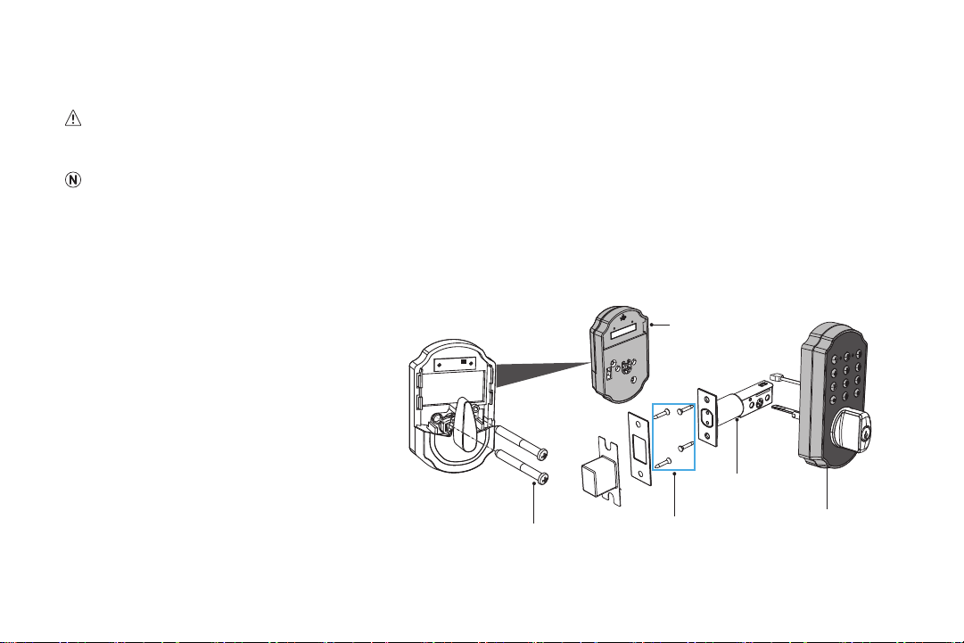
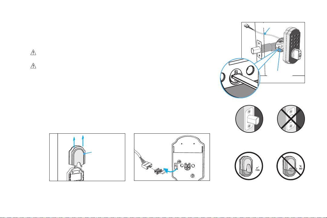
Part 1 - Disassemble the Lock
The TL115 comes already assembled. Before
installation, release the wood screws and
mounting screws to disassemble the lock into
three main parts: Outside Assembly x 1, Inside
Assembly x 1, Latch Assembly x 1 (Fig. 1).
Wood Screws
Mounting Screws
Inside Assembly
Outside Assembly
Latch Assembly
(Fig. 1)
TURBOLOCK TL115 9
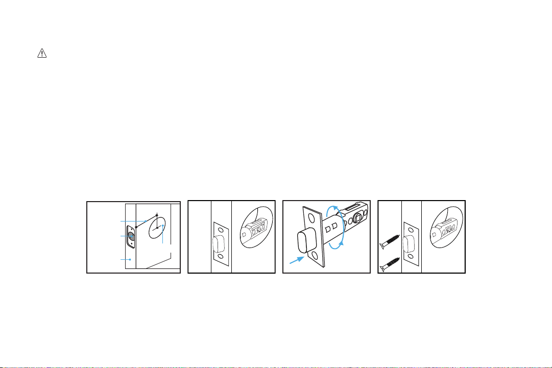
Part 2 - Installing the Latch
KEEP DOOR OPEN AT ALL TIMES SHORTLY BEFORE, DURING AND SHORTLY AFTER INSTALLATION. If the lock is
incomplete or improperly installed, the lock and/or door may become stuck.
After nishing installation, be sure to use the door at least once to make sure all parts of the lock function correctly.
Step 1. Check the dimensions of the door before installing the latch (Fig. 2).
Step 2. Insert the latch into the hole and check it. The latch’s plate should sit ush against the edge of the door (Fig. 3). If
there’s too much space behind the latch or if it’s sticking out from the door, the latch should be adjusted. If the latch
needs adjusting, continue on to Step 3; otherwise, go to Step 4.
Step 3. Turn the latch and extend or retract it as needed. Make sure the metal peg pops into one of the two square holes in the
side and the deadbolt is pushed all the way in while adjusting the latch’s length (Fig. 4). Insert the latch back into the
door.
Step 4. Add 2x wood screws and use a screwdriver (not included) to secure them (Fig. 5).
2
3/4” (70mm)
Or
2
3/8” (60mm)
2
1/8” (54mm)
Hole
1
” (25mm)
Door Edge
2
3/4
”
2
3/8
”
(Fig. 2) (Fig. 3) (Fig. 4) (Fig. 5)
2
3/4
”
2
3/8
”
2
3
/
4
”
2
3/
8
”
Part 3 - Installing the Strike
In most cases, the existing strike plate and setup can be used. If you wish to use the one included with your lock, skip to Section
4.1, Part 3.
10 TURBOLOCK TL115
3.2 Main Installation
Step 1. Start with the outside section. Feed the power cable above the latch and thread
the latch pin through the square hole in latch. The latch pin must be horizontal
while inserting the square hole in latch (Fig. 6).
Do NOT force the cable’s connector end through any part of the lock.
Damaging the connector may make the lock unusable.
It’s highly recommended to leave the door open during installation. And
always keep the bolt extended throughout the installation (Fig. 7).
Step 2. If needed, have someone hold the door itself or hold the outside section at
against the front of the door. Then take out the inside section, and turn the
thumb vertically before installing (Fig. 8).
Step 3. Remove the battery compartment cover on the inside section (Fig. 9).
Step 4. Gently feed the other power cable through the hole of inside section to snap it into
the cable connectors. Then feed the connected power cable into the hole of door
(Fig. 10).
Horizontal
Latch Pin
Fig. 6
Power Cable
Compartment
Cover
Fig. 9
Fig. 10
Extended Retracted
Fig. 7
Fig. 8
TURBOLOCK TL115 11
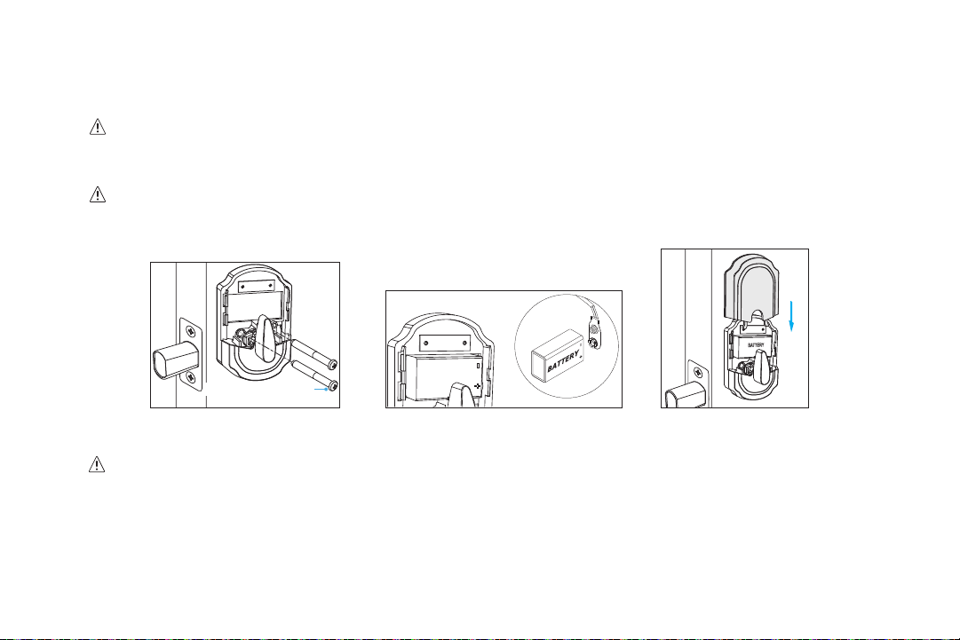
Step 5. Align the mounting holes of inside section with the two round holes near the square hole in latch, then use the two
mounting screws to install the inside section on the door (Fig. 11)
Always keep the bolt extended and the thumb turn vertical throughout throghout the installation (Figs. 7 & 8).
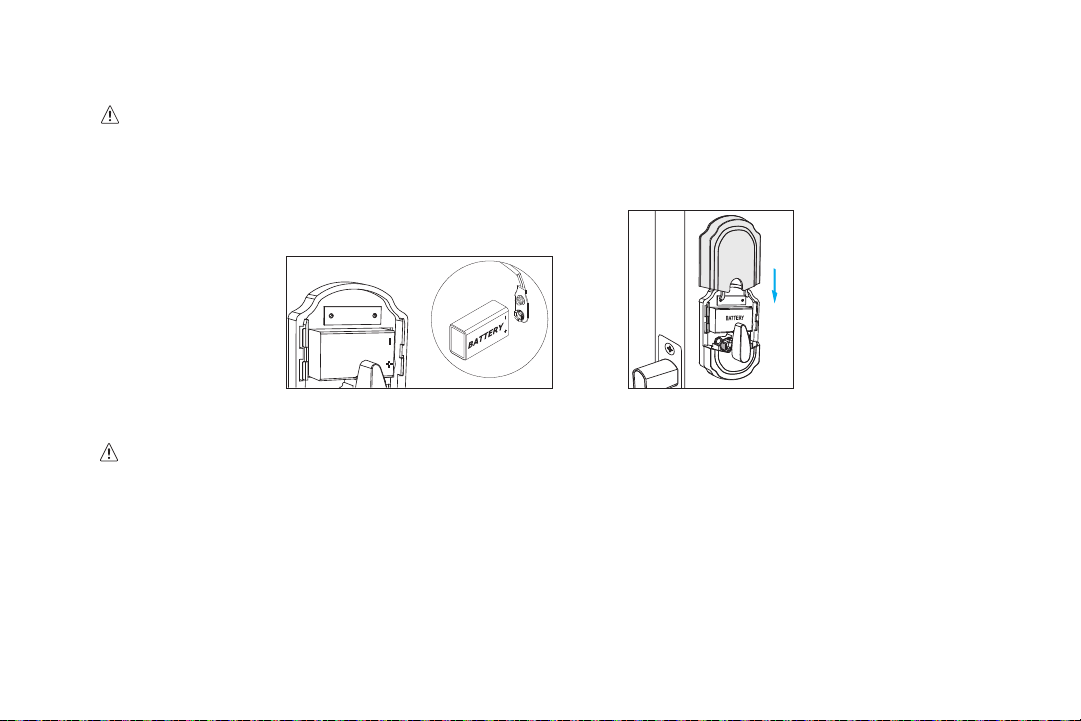
Step 6. Install the included 9V alkaline battery or rechargeable battery into battery compartment (Fig. 12).
Make sure the positive and negative pole connection is correct.
Step 7. Slide down the compartment cover to complete the installation (Fig. 13).
BATTERY
Fig. 11 Fig. 12
Mounting Screws
Fig. 13
Do NOT force the cable’s connector end through any part of the lock. Damaging the connector will make the lock
unusable.
Step 8. The lock should now be ready to use. It’s highly recommended to use the default passcode and the app to test
the lock before closing the door. See Section 6 for information on the default admin passcode. See Section 8 for
information on the app.

12 TURBOLOCK TL115
Section 4
Installation (New)
This section details installation steps needed if you are installing the TL115 on a door
without a cutout. If you are using the TL115 to replace an old lock or if your door otherwise
already has a cutout, please go back to Section 3.
• For easier installation, have another person help to hold the lock.
• For your convenience, installation instructions are broken into segments. Read and follow the
instructions for both Pre-Installation and Main Installation.
4.1 Pre-Installation
Part 1 Making the Opening
Step 1. Using the provided template, mark the locations for the centers of the backset and the
latch hole (Fig. 14).
Step 2. Bore a 54mm (about 2” or 2 1/8”) hole on door face, then drill a 25mm (about 1”) hole into
the edge of the door so that it intersects with the larger hole (Fig. 15).
• When drilling the 54mm (about 2” or 2 1/8”) hole, it’s recommended to drill from both sides of
door to stop the wood from splintering.
• It may be easier to drill the 54mm hole with a hole saw bit (not included).
• It may be easier to drill the 25mm hole with a hole saw bit (not included) or a 7/8” spade bit (not included). If using a spade bit,
do not drill at high speeds as this may tear out too much wood and/or damage the door.
Mark Hole
Latch Hole
Backset
Side Hole
2” diameter hole
1” diameter hole
Fig. 14
Fig. 15
(Fig. 17)
(Fig. 16)
TURBOLOCK TL115 13
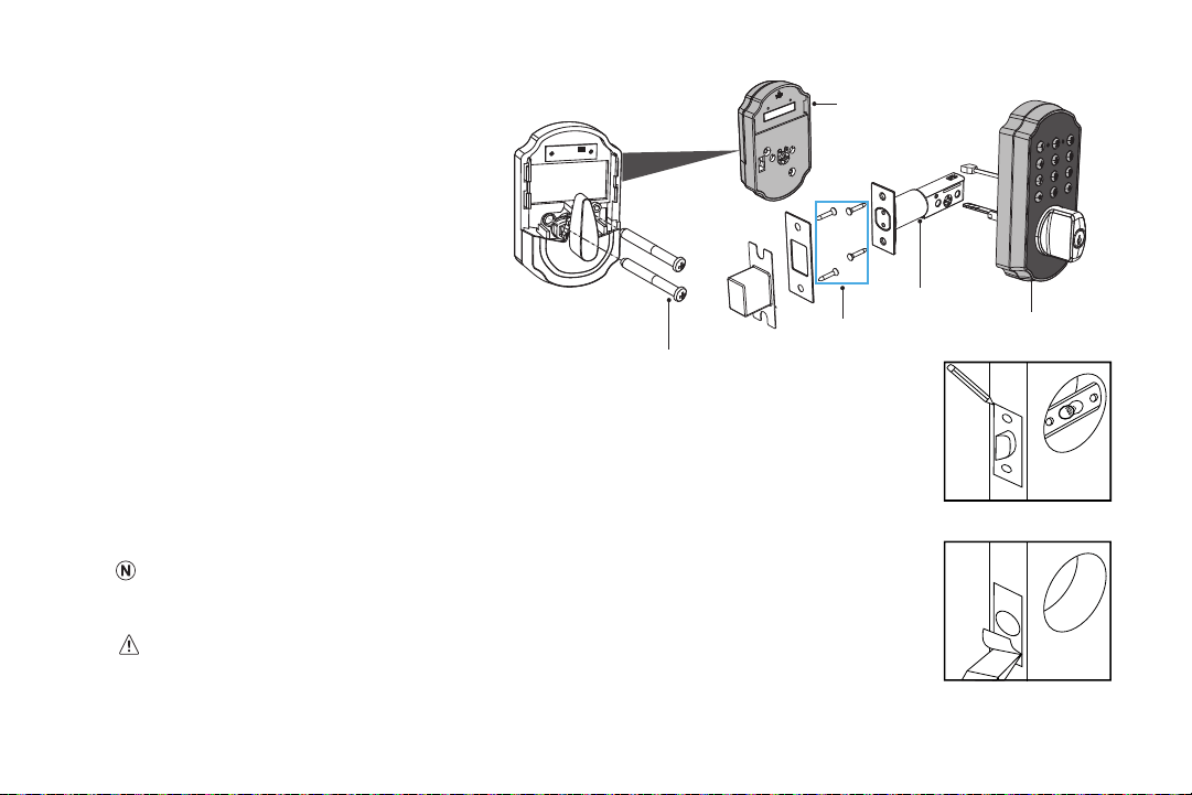
Part 2 - Disassemble the Lock
The lock is pre-assembled upon arrival. Before
installation, loosen the wood screws and
mounting screws to separate the lock into three
main parts:
Outside Assembly x 1
Inside Assembly x 1
Latch Assembly x 1
Part 3 - Installing the Latch
Step 1. Insert the latch into the hole. Using a pencil, mark a line around edge of latch plate to use as
a guide. After marking at all four sides of the plate, remove the latch (Fig. 16).
Step 2. Chisel about 3mm (0.1”) deep or until latch plate sits ush with door edge (Fig. 17).
During chiseling, it’s highly recommended to stop and reinsert the latch every once in a while to
see if it sits ush. If not, chisel a little more and check again.
Be careful not to chisel too deep; otherwise, the lock may not function correctly after installation.
Wood Screws
Mounting Screws
Inside Assembly
Outside Assembly
Latch Assembly

14 TURBOLOCK TL115
Step 3. Insert the latch into the hole and check it. The latch’s plate should sit ush against the edge of the door (Fig. 3). If
there’s too much space behind the latch, or if it’s sticking out of the door, the latch should be adjusted. If the latch
needs adjusted, move to Step 4; otherwise, skip to Step 5.
Step 4. Hold the front of the latch and the square opening from both sides, pull or push to extend or retract the latch end as
needed (Fig. 4). Insert the latch back into the door.
Step 5. Check the latch’s bolt and make sure the rounded side faces in. Use the 2x Wood
Screws and a screwdriver (not included) to secure them (Fig. 5).
Part 4 - Creating a Mortise & Installing the Strike
Step 1. Push the door until nearly closed and check where the latch’s bolt touches the frame.
Step 2. Use a pencil to mark the horizontal center of the latch on the door frame (Fig. 18).
Step 3. Open the door again and extend the line over the edge of the door and inside the
frame.
Step 4. Measure the inside of the frame. Determine and mark the halfway point. From this
point, use a ruler to draw a line straight down so that it intersects the existing line (Fig.
19).
Step 5. Use a 7/8” (22.2mm) spade bit and a drill to make two partially overlapping holes
about 0.6” (15mm) deep centered both above and below the center line. If needed,
use the chisel to make the hollow (aka “mortise”) more square. If you choose to use
the strike box, you may need to chisel slightly deeper (Fig. 20).
If using a spade bit, do not drill at high speeds as this may tear out extra wood and/or
damage the door or doorframe.
2
3
/
4
”
2
3
/
8
”
(Fig. 18)
(Fig. 19)
(Fig. 20)
TURBOLOCK TL115 15
Step 6. Hold the strike plate over the mortise. Using a pencil, mark a line around the
edges of plate to use as a guide. After marking at the straight edges of the
plate, remove the plate.
Step 7. Chisel about 1.5mm deep or until strike plate sits ush with door frame.
• If you choose to use the strike box, you may need to chisel slightly deeper.
• During chiseling, it’s highly recommended to stop and check to see if the strike
plate sits ush in the doorframe over the strike box. If not, chisel a little more and
check again.
Be careful not to chisel too deep; otherwise, the lock may not function correctly after installation.
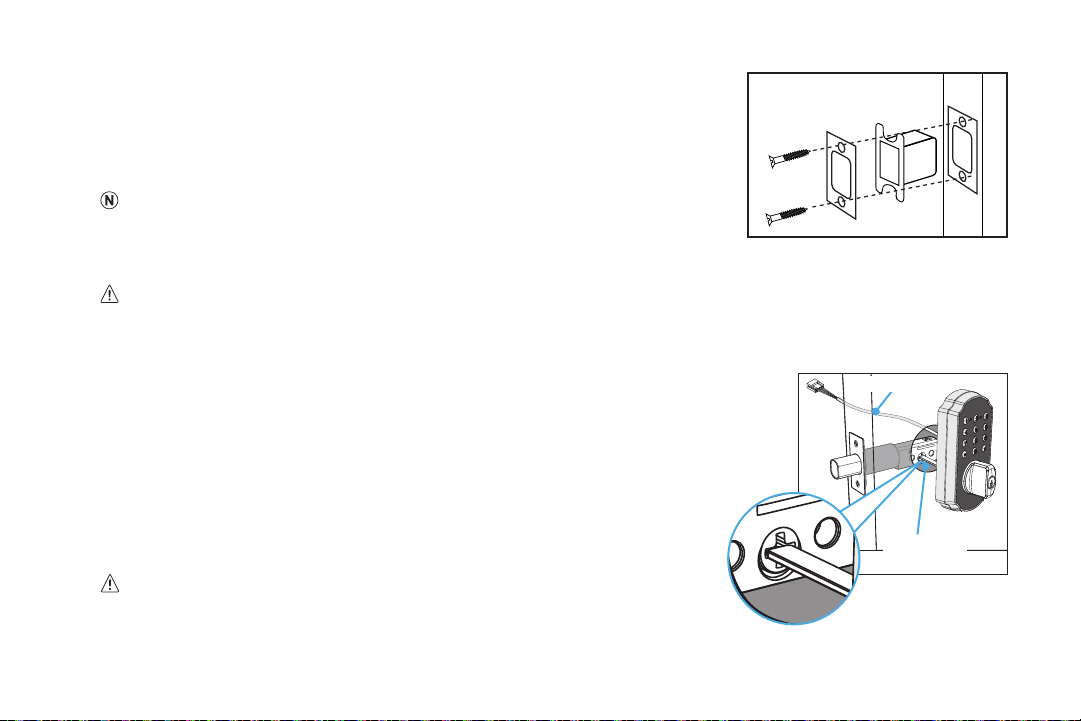
Step 8. Position the strike and strike box, then use a pencil to mark the center points of the screw openings in the strike plate.
Set the strike and strike box aside and drill two small holes at each center point.
Step 9. Position the strike and strike box. Add the two remaining Wood Screws and use
a screwdriver (not included) to secure them (Fig. 20).
4.2 Main Installation
Step 1. Start with the outside section. Feed the power cable above the latch and thread
the latch pin through the square hole in latch. The latch pin must be horizontal
while inserting the square hole in latch (Fig. 6).
Do NOT force the cable’s connector end through any part of the lock.
Damaging the connector may make the lock unusable.
(Fig. 21)
Horizontal
Latch Pin
Fig. 6
Power Cable

16 TURBOLOCK TL115
It’s highly recommended to leave the door open during installation. And always
keep the bolt extended throughout the installation (Fig. 7).
Step 2. If needed, have someone hold the door itself or hold the outside section at against
the front of the door. Then take out the inside section, and turn the thumb vertically
before installing (Fig. 8).
Step 3. Remove the battery compartment cover on the inside section (Fig. 9).
Step 4. Gently feed the other power cable through the hole of inside section to snap it into
the cable connectors. Then feed the connected power cable into the hole of door
(Fig. 10).
Step 5. Align the mounting holes of inside section with the two round holes near the square hole in latch, then use the two
mounting screws to install the inside section on the door (Fig. 11).
Always keep the bolt extended and the thumb turn vertical throughout the installation (Figs. 7 & 8).
Extended Retracted
Fig. 7
Fig. 8
Compartment
Cover
Fig. 9
Fig. 10
Fig. 11
Mounting Screws
TURBOLOCK TL115 17
Step 6. Install the included 9V alkaline battery or rechargeable battery into battery compartment (Fig. 12).
Make sure the positive and negative pole connection is correct.
Step 7. Slide down the compartment cover to complete the installation (Fig. 13).
BATTERY
Fig. 12 Fig. 13
Do NOT force the cable’s connector end through any part of the lock. Damaging the connector will make the lock
unusable.
Step 8. The lock should now be ready to use. It’s highly recommended to use the default Passcode and the app to test the lock
before closing the door. See Section 6 for information on the default admin Passcode. See Section 8 for information on
the app.

18 TURBOLOCK TL115
Section 5
Using the Lock
To unlock the TL115, use the keypad to enter the passcode, then press ‘#’. The TL115 will unlock after the voice conrmation
(“Opened”) and will automatically lock again after a few seconds.
The Admin Passcode must be changed from the default. See Section 6.
The lock can also be unlocked via the app. Refer to Section 8.
Section 6
Keypad Passcodes
6.1 Changing the Admin Passcode
• The Admin Passcode must always be exactly 6 digits long.
• The default Admin Passcode is ‘123456’.
For security, it is highly recommended that you change the Admin Passcode from the manufacturer default.
Step 1. Press the ‘#’ on the keypad, and enter the current Admin Passcode then press ‘#’. Voice navigation will guide you
through the process:
“To set up an Admin Passcode, please press 1.”
Step 2. Enter ‘1’ then press ‘#’.
Step 3. Enter the new Admin Passcode, then press ‘#’. After the voice conrmation (“Success”), the new Admin Passcode is
saved.
Step 4. Test the new Admin Passcode to conrm the modication was successful.
• The Passcode must be entered while the keypad backlight is on. If it goes out, begin again at Step 1.
• If the Admin Passcode is lost or forgotten, the lock may be reset. Refer to Section 9.

TURBOLOCK TL115 19
6.2 Adding Keypad Passcodes
Keypad passcodes can be generated so that more people can gain entry access as needed.
USE WITH CAUTION. Anyone with the keypad passcode can unlock the TL115 until the keypad passcode is deleted. If more
control is needed, refer to Section 8.
• The admin must create passcodes for users.
• Keypad passcodes must be 6 digits long.
• The TL115 can hold up to 9 keypad passcodes.
Step 1. Press ‘#’ on the keypad, and enter the current Admin Passcode. Then press ‘#’ again. Voice navigation will guide you
through the process:
“To set up a user passcodes, please press 2.”
Step 2. Enter ‘2’ then press ‘#’. Follow the voice prompt:
“Please enter the new user passcode.”
Step 3. Enter a new keypad passcode, and then press ‘#’. After the voice conrmation (“Success”), the new passcode has
been saved.
You can create multiple passcodes (up to 9 total) in Step 3 so long as the keypad backlight is still on. If the keypad backlight
turns o, you must go back to Step 1 to create a new keypad passcode.
Step 4. Test the new passcode(s) to conrm the modication was successful.

20 TURBOLOCK TL115
6.3 Delete a Single Passcode
Step 1. Press ‘#’ on the keypad, and enter the current Admin Passcode. Then press ‘#’ again. Voice navigation will guide you
through the process:
“To delete a user passcode, please press 3.”
Step 2. Enter ‘3’ then press ‘#’ before the keypad turns o.
Step 3. Before the keypad turns o, enter the passcode you want to delete, then press ‘#’ .
Step 4. After the voice conrmation (“Success”), the old passcode should be deleted.
Step 5. Test the old Passcode. It should now be unusable.
6.4 Delete All Passcodes
Step 1. Pres
s ‘#’ on the keypad, and enter the current Admin Passcode. Then press ‘#’
again
.
Step 2. Voice navigation will guide you through the process:
“To erase all user passcodes, please press 4.”
Step 3. Enter ‘4’ then press ‘#’ before the keypad turns o.
Step 4. After the voice conrmation (“All user passcodes successfully deleted”), the keypad will turn o. All passcodes are now
deleted.
Step 4. Test all previous keypad passcodes. They should now be unusable.
6.5 Passcode Disguise
This function is an added security feature aimed at preventing Passcode theft. With Passcode Disguise, you may enter 12 digits
into the keypad. As long as the correct Passcode sequence is entered, regardless of how many digits were entered before or
afterwards, the TL115 will unlock.

TURBOLOCK TL115 21
For example, if your user Passcode is “080808”, you can successfully unlock the TL115 by entering “11354080808”, “11080808”,
“10808081” and so on.
Section 7
Using the Mute Function
USE WITH CAUTION. Remember to turn o the function when it is no longer needed. Do not leave this function on for extended
periods of time. Mute mode will disable all notications, excluding the low-battery warning.
7.1 Activating Mute Mode
Step 1. Press
‘#’ on the keypad, and
enter the current Admin Passcode. Then press
‘#’
again. Voice navigation will guide you
through the process:
“To activate mute function, please press 6.”
Step 2. Press ‘6’ and then ‘#’. After the voice conrmation (“Mute mode activated”), the TL115 will be muted and will remain so
until the feature is turned o.
7.2 Deactivating Mute Mode
Step 1. Press
‘#’ on the keypad, and
enter the current Admin Passcode. Then press
‘#’
again
. Voice navigation will guide you
through the process:
“To activate mute function, please press 6.”
Step 2. Press ‘6’ and then press ‘#’. After the voice conrmation ("Mute mode deactivated.") and the keypad lights o, Mute
mode is deactivated.
Section 8
The TurboLock Plus App
The TurboLock Plus app, compatible with most Android and iOS smartphones, grants access to all of the TL115’s features.
Through the app, you can unlock the TL115, create and send passcodes (E-Keys), track unlocking records and more. To get the
app, follow the instructions below.

Fig. 1
22 TURBOLOCK TL115
8.1 App Installation
Step 1. On your smartphone, search for the “TurboLock Plus” app in the Google Play or App Store.
Step 2. Download and install the app.
Step 3. Turn on your smartphone’s Bluetooth
®
function and open the app.
Step 4. Register for an account and reopen the app.
8.2 Pairing
For the rst time pairing
Step 1. Open the app, tap the icon on the lock list screen, then select the lock. The app will
begin pairing.
Step 2. Tap any conrmation messages as needed.
Pairing to another smartphone
To pair a dierent smartphone with the lock, you must reset the lock using the steps below. Resetting the lock will revert the Admin
Passcode to the default and delete all user and keypad passcodes. After the new smartphone is paired to the lock, the previous
phone will no longer have Admin privileges.
For App operations, there is only one admin, but there can be multiple users.
Step 1. Press ‘#‘ on the keypad, enter your current Admin Passcode, then press ‘#’. The lock is now in Setup mode. Follow the
prompts or the steps below to reset the lock.
Step 2. Press ‘5’ then ‘#’. The TL115 will reset and enter the sleep mode.
Step 3. Open the app, tap the icon on the lock list screen, then select the lock. The app will begin pairing.
Step 4. Tap any conrmation messages as needed. The TL115 might beep and open upon pairing for the rst time.
TURBOLOCK TL115 23
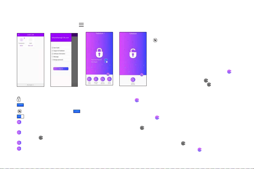
8.3 App Usage
From the lock list screen (Fig. 2), tap get more information about lock service (Fig. 3). Or tap the name of lock to enter operation
screen (Fig. 4 and Fig. 5).
Fig. 2 Fig. 3
Main Interface (Admin View)
Fig. 4
Main Interface (User View)
Fig. 5
: Tap to open the lock. Make sure the Bluetooth status icon is lit up ( ).
: Tap to Reset Temp Passcode.
Keep the app connected. Tap before generating any passcode for the rst time use.
: Slide to toggle the Mute feature. Make sure the Bluetooth status icon is lit up ( ).
Send E-Key: Tap to enter the Send E-Key screen. From here, you can send E-keys to other users or generate temporary
keypad unlock codes, even if the Bluetooth status icon is grayed out ( ).
Manage E-Key: Tap to enter Manage E-Key screen. From here, you can delete unlock codes, even if the Bluetooth status icon
is lit o ( ).
Unlock Records: Tap to view recent unlock records, even if the Bluetooth status icon is lit o ( ).
Reset Admin: Tap to reset admin passcode. Bluetooth status icon must indicate successful connection ( ).
• Images for illustrative purposes only. Actual
content may vary.
• App content subject to change without
notication.
• App content may dier depending on
operating system.
• Before using App to open the lock, make
sure the Bluetooth status icon is lit up ( ).
This means it has connected successfully.
If the icon is grayed out ( ) this means the
lock is not connected. Tap to connect.
24 TURBOLOCK TL115
Fig. 6
Fig. 7
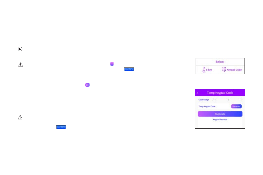
8.4 Generating Keypad Passcodes
For users without the TurboLock Plus app, the Admin can generate a 6-digit passcode that users can manually enter on the TL115
keypad to unlock. This 6-digit code can be revoked at any time by the Admin. This is a temporary unlock code that can be used 1-3
times, as assigned by the Admin.
Keypad passcodes should only be used for temporary access. For permanent access, it is highly recommended to add E-Keys.
For instructions, refer to Section 8.5.
FIRST TIME USE: Make sure the app is connected ( ). Before you can generate temporary
(keypad) passcodes, you MUST tap “Reset Temp Passcode” on the app home screen.
Generate Keypad Passcodes in App
Step 1. After opening the app, tap to enter the Send E-Key screen.
Step 2. Tap “Keypad Code” to enter the Send Keypad Code screen.
Step 3. Code Usage limits the number of times a keypad code can be used: 1 for one-time
use, 2 for two-time use, and so on. Set the number of uses (Code Usage) for this
passcode, between 1 and 3, then tap Generate (Fig.7).
You may generate up to 300 temporary (keypad) passcodes (100 for each Code Usage). After
this limit is reached, you will not be able to create any new passcodes until you tap “Reset
Temp Passcode” (
) in the app home screen.
TURBOLOCK TL115 25
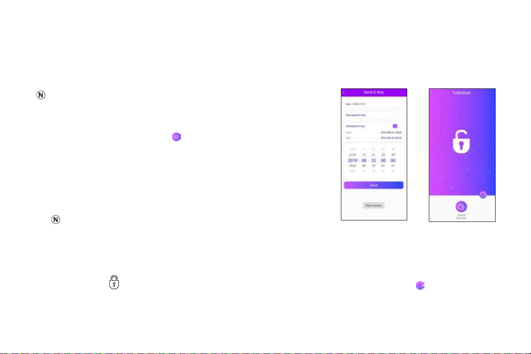
8.5 Managing User Passcodes (E-Keys)
User Passcodes (E-Keys) are generated on the TurboLock Plus app by the Admin and sent to a user. That user must install the
TurboLock Plus app on their smartphone and register for a TURBOLOCK account.
E-Keys can be permanent or have time restrictions, at the Admin’s discretion.
Generate E-Keys in App
Step 1.
After opening the app, tap to enter the Send E-Key screen.
Step 2. Tap “E-Key” to enter the Send E-Key screen.
Step 3. Enter the user’s E-mail or phone number (whichever the user registered
with) (Fig. 8).
Step 4. Select “Scheduled E-Key” if you wish for the E-Key to be temporary;
otherwise, select “Permanent E-Key.”
Permanent E-Keys can be deleted on the Manage E-Keys section of the app.
Use E-Keys in App
After E-Keys are successfully shared, the users can use the E-Keys to open the lock in App.
Step 1. Log in the TurboLock Plus app with the user’s account to enter the User View (Fig. 24).
Step 2. Tap the icon in the app screen to open the lock. Make sure the Bluetooth status icon is lit up ( ).
Fig. 27
Main Interface (User View)
Fig. 24
26 TURBOLOCK TL115
Section 9
Resetting the Lock
• Resets cannot be reversed.
• Performing a reset will delete all Passcodes including the Admin Passcode..
• Once all Passcodes are erased, only the default Admin Passcode can open the lock.
• After a reset:
○ Admin Passcode reverts to default: 123456.
○ Choose a new Admin Passcode immediately. See Section 6.
○ All digital keys and codes issued via the app will be erased. In order to restore app
functionality, it must be paired with the lock again. See Section 8.2.
Option 1
Step 1. Pres
s ‘#’ on the keypad, enter the current Admin Passcode, then press
‘#’ again. Voice navigation will guide you
through the process:
“To restore the default factory setting, please press 5.”
Step 2. Press ‘5’ followed by ‘#’ before the lock’s backlight turns o. The TL115 will conrm “Restore factory settings,” then
ash three times. After the voice conrmation (“Success”), the TL115 is now reset.
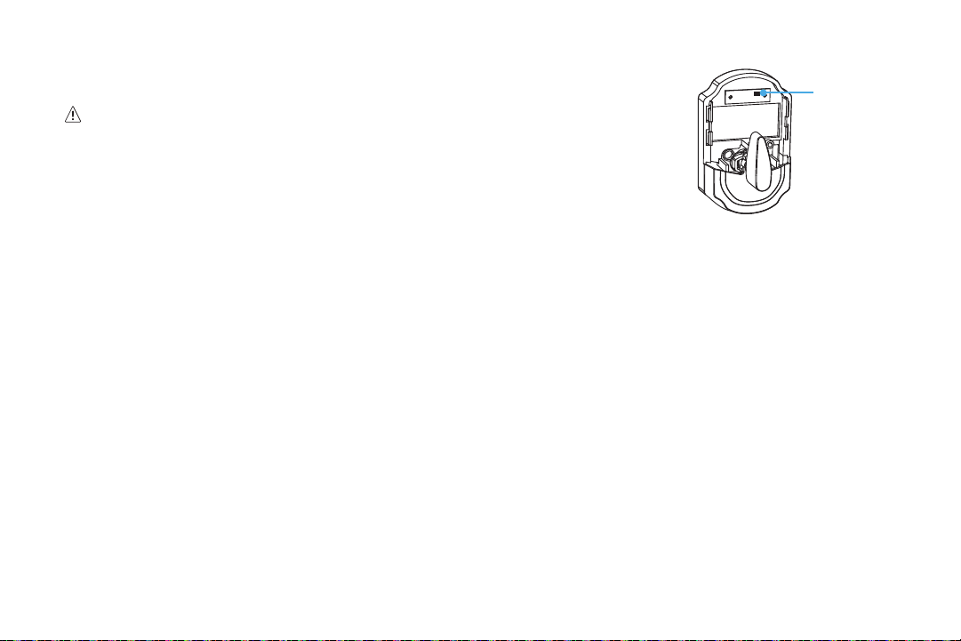
Option 2
Step 1. Remove the cover from the battery compartment at the back of the lock.
Step 2. Press and hold the little black button above the battery compartment for ~5 seconds. The TL115 will conrm “Restore
factory settings,” then ash three times. After the voice conrmation (“Success”), the TL115 is now reset.
Inside Section
Reset Button

TURBOLOCK TL115 27
Section 10
Specications
Item Description
Model Name TL115
Battery Type 9V alkaline battery
Net Weight 2.6 lb / 1.2 kg
Dimensions 5.3 x 5.9 x 3.0 in (135 x 149 x 76.6 mm)
Material Zinc alloy
Deadbolt Spring
Stand-by Consumption <70uA
Physical Keys 3
Number of E-Keys Unlimited
Temporary Keypad Codes Up to 300 temporary (keypad) passcodes can be generated from the app, distributed evenly
between the three Code Usage limits.
Keypad Codes 9 user, 1 admin
Passcode Length 6 digits
Pressing Cycle times >200,000
Application Systems Requests IOS 9.0 or Android 5.1 above
Micro USB 1 x USB (mobile power bank)
Usage Temp.
-4°F~140°F (-20°C~60°C)
Door requirements 2.16” (5.5cm) diameter hole, 1.38” - 2.16” (3.5cm - 5.5cm) thickness
Warranty 1 Year Limited

28 TURBOLOCK TL115
Section 11
Maintenance
Proper cleaning and maintenance of your lock ensures it will continue to work as it should.
• For most cleaning purposes, use clean (or puried) water and a soft, non-abrasive cloth.
• If a mess cannot be cleaned with water, apply a gentle cleaner to the cloth and clean.
• Do not apply cleaner or detergent directly to any part of the lock.
• After cleaning with a cleaner or detergent, wipe o any residue using a second non-abrasive cloth. Be sure to dampen the
cloth with clean (puried) water.
• The TL115 meets IP65 water-resistance. It can withstand splashes and contact with water once properly installed; however, do
not submerge the lock.
• Do not let water and liquids get into the lock’s electric parts or battery compartment.
Section 12
Troubleshooting
Problem Possible Cause Solution(s)
Why can’t I open the
door?
Too much time has passed. Try passcode again. Remember to turn the handle to
open the door while the lock’s backlight is still on.
Your access has been restricted. If you received a key from the lock’s admin, your access
may have a restricted schedule. Check with your admin
regarding these details.

TURBOLOCK TL115 29
Problem Possible Cause Solution(s)
Why does the lock
jam? / The door doesn’t
close.
The latch size is wrong. Disassemble the lock and check the latch assembly.
If retrotting, compare the latch length and adjust as
needed. If installed on a new door, adjust the latch and/
or, drill into the door to t the latch as needed.
The strike plate and latch aren’t correctly
aligned.
Open the door and check the alignment of both the latch
and the strike plate. Adjust as needed.
The lock doesn’t work. The lock isn’t receiving power. Ensure the batteries are properly installed. Remove and
reinstall if needed.
The batteries are entirely dead and/or
were not replaced in a timely manner.
Replace the batteries.
Use one of the physical keys to lock and unlock the
TL115. Replace the batteries.
Use the emergency power port to power the lock so that
the door opens. Replace the batteries.
Can not generate
temporary keypad
passcodes from app?
For the rst time use, didn’t tap “Reset
Temp Passcode” (
) on the app
home screen, or even you have tap
, still fail to generate temporary
keypad passcodes.
For the FIRST TIME USE: Make sure the app is
connected. Tap “Reset Temp Passcode” ( ) on the
app home screen then proceed to generate temporary
(keypad) passcodes.
The 300 temporary keypad passcodes
limit is reached.
New Passcodes cannot be generated if the limit is
reached. Make sure the app is still connected, and tap
“Reset Temp Passcode” on the app home screen again
to generate new passcodes.

30 TURBOLOCK TL115
Problem Possible Cause Solution(s)
I appear to be locked
out. Not even my admin
Passcode works.
If a passcode has been entered wrong
5x in a row, regardless of the entry
method, the lock will go into a 5-minute
security lockdown. This is a feature
designed to prevent unwanted parties
from attempting to guess passcodes.
Wait 5 minutes and try again, or use the physical key to
open the lock directly.
The physical key can be used to override the
security lockout.
Lock indicator ashes
red.
Low battery warning New batteries should be installed as soon as possible
after receiving the rst low-battery warning.
I forgot my codes. The codes were not properly recorded. Perform a reset in order to erase all Passcodes. If you
do not remember your Admin Passcode, you must have
access to the back of the door to perform a reset. Once
the reset is complete, all passcodes will be erased and
the Admin Passcode will return to the default value (see
Section 6).
You will need to pair the TL115 to your smartphone
again. See Section 8.2 for details.
If none of the above resolves your issue, please visit our website at www.turbolock.com or contact customer service at
855-850-8031.

TURBOLOCK TL115 31
Section 13
Warranty
13.1 Violation
The lock cannot be repaired or serviced within its warranty period if any of the following has occurred:
• The warranty has expired
• Damage occurred during or in relation to non-routine and/or unauthorized disassembly
• Failure to provide a valid proof of purchase when requesting service or repair
• Damage occurred as a result of natural disaster etc.
• Damage occurred due to unexpected factors or man-made reasons (including mis-operation, uid found in any openings, improper
insertion or pulling, hauling, bumping, improper voltage input and others)
13.2 Information
One-Year Limited Hardware Warranty
Your TURBOLOCK TL115 Bluetooth-enabled Smartlock (“Product”) includes a One-Year Limited Hardware Warranty (“Warranty”).
The Warranty covers product defects in materials and workmanship under normal use. This Warranty is limited to residents of the
United States and Canada only and is available only to original purchasers. This Warranty gives you specic legal rights and you
may also have other rights which vary from state to state.
This W
arranty starts on the date of your purchase and lasts for one (1) year (the “Warranty Period”). The Warranty Period is not
extended if the Product is repaired or replaced. We may change the availability of this limited warranty at our discretion, but any
changes will not be retroactive.
Warranty services are provided by TURBOLOCK Warranty Pro (“WP”). If a hardware defect arises and a valid claim is received
within the Warranty Period, at its option and to the extent permitted by law, WP will: (1) repair the hardware defect by using new or
refurbished parts that are equivalent to new in performance and reliability; or (2) exchange the Product with a product that is new or
refurbished which is substantially equivalent to the original product. This Warranty is for one replacement only of like-items and does

32 TURBOLOCK TL115
not cover items out of production if the product is no longer made or stocked. This Warranty is not assignable or transferable. The
original purchaser may call the toll-free number at 1-855-850-8031 for service requests.
When a product or part is exchanged, any replacement item becomes your property and the replaced item becomes WP’s property.
This warranty only covers technical hardware defectiveness during the warranty period and under normal use conditions. WP does
not warrant uninterrupted or error-free operation of this Product.
This Warranty does not cover any damage due to: (a) transportation; (b) storage; (c) improper use; (d) failure to follow the product
instructions or to perform any preventive maintenance; (e) modications; (f) unauthorized repair; (g) normal wear and tear; or (h)
external causes such as accidents, abuse, or other actions or events beyond our reasonable control.
Important: Do not disassemble the Product. Disassembling the Product will void this Warranty. Only WP or a party expressly
authorized by WP should perform service on this Product.
DISCLAIMER OF WARRANTY: THE REMEDIES DESCRIBED ABOVE ARE YOUR SOLE AND EXCLUSIVE REMEDIES AND OUR
ENTIRE LIABILITY FOR ANY BREACH OF THIS LIMITED WARRANTY. OUR LIABILITY SHALL UNDER NO CIRCUMSTANCES
EXCEED THE ACTUAL AMOUNT PAID BY YOU FOR THE DEFECTIVE PRODUCT, NOR SHALL WE UNDER ANY
CIRCUMSTANCES BE LIABLE FOR ANY CONSEQUENTIAL, INCIDENTAL, SPECIAL OR PUNITIVE DAMAGES OR LOSSES,
WHETHER DIRECT OR INDIRECT.
SOME STATES DO NOT ALLOW THE EXCLUSION OR LIMITATION OF INCIDENTAL OR CONSEQUENTIAL DAMAGES, SO
THE ABOVE LIMITATION OR EXCLUSION MAY NOT APPLY TO YOU.
THE DURATION AND REMEDIES OF ALL IMPLIED WARRANTIES, INCLUDING WITHOUT LIMITATION THE WARRANTIES OF
MERCHANTABILITY AND FITNESS FOR A PARTICULAR PURPOSE ARE LIMITED TO THE DURATION OF THIS EXPRESS
LIMITED WARRANTY.


COPYRIGHT © 2019 TURBOLOCK. ALL RIGHTS RESERVED.