
JL AUDIO
®
AP AMPLIFIERS
Installation Instructions
Important Safety Information
WARNING
See the Important Safety and Product Information guide in the product box for product warnings and other
important information.
This device must be installed according to these instructions. Failure to install this device in accordance with
these instructions could result in serious personal injury, damage to the device and/or vessel, or poor product
performance.
Disconnect the power supply to the vessel's audio system before beginning to install this device. To avoid
possible serious personal injury or damage to the device and vessel, disconnect the power supply to the
vessel's audio system before beginning to install the device.
Continuous exposure to sound pressure levels over 100dBA may cause permanent hearing loss. The volume
is typically too loud if you cannot hear people speaking around you. Limit the amount of time you listen at high
volume. If you experience ringing in your ears or muffled speech, stop listening and have your hearing checked.
The wiring from the power source to the amplifier must run through an inline fuse or circuit breaker (not
included) as close to the power source as possible. You must connect the positive wire to the fuse or circuit
breaker. Connecting the amplifier to power without an inline fuse or circuit breaker may result in a fire if there is
a short in the cable.
CAUTION
Install in a dry, well-ventilated location that does not interfere with your factory-installed systems. Mount this
product securely to prevent damage or injury in severe conditions. Carefully route all system wiring away from
moving parts and sharp edges; secure with cable ties or wire clamps and use grommets and loom where
appropriate to protect from sharp edges.
To avoid possible personal injury, always wear safety goggles, ear protection, and a dust mask when drilling,
cutting, or sanding.
NOTICE
Only use this product with 12 volt, negative-ground electrical systems. This product is not certified or approved
for use in aircraft.
For ABYC
®
and NMEA
®
applications, circuit protection is required within 18 cm (7 in.) of the battery, unless the
cable is an enclosure or a conduit.
This product is water-resistant. Do not submerge the device or subject it to high-pressure water spray. Exposure
to water pressures beyond the listed water rating can damage the device.
When drilling or cutting, always check what is on the opposite side of the surface to avoid damaging the vessel.
It is strongly recommended that you have your audio system installed by a professional installer to ensure
optimum performance.
You must read all installation instructions before beginning the installation. If you experience difficulty during
the installation, go to support.garmin.com for product support.
After installing an audio system, you should run the connected speakers and subwoofers at low to medium
volumes during their first few hours of use. This helps to improve the overall sound by gradually loosening
up the moving components in the new speakers and subwoofers, such as the cone, spider, and surround.
See the installation instructions provided with your speakers, because there may be more details about the
recommended low-to-medium volume usage time for each model.
January 2026 GUID-825043EC-AB52-4D71-959C-5ABABAC34D9B v3
Tools Needed
● Phillips screwdriver
● Drill
● 3 mm (
1
/
8
in.) drill bit
Model Numbers
These instructions cover the installation and operation for three models of JL Audio
®
AP amplifiers.
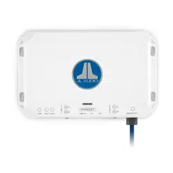
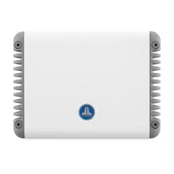
JL Audio AP300/1 Monoblock Amplifier
JL Audio AP300/4 4-Channel Amplifier
JL Audio AP600/6 6-Channel Amplifier
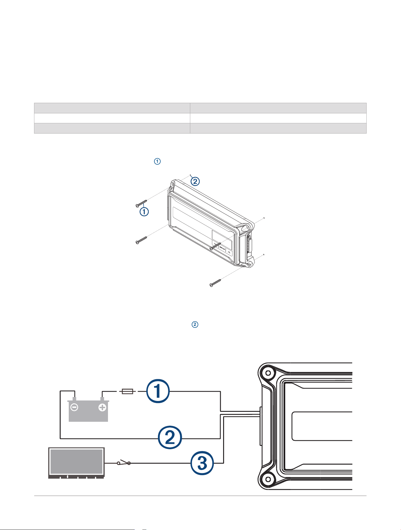
Mounting the Amplifier
1 Identify the four M4 x 35 mm screws
1
included with the device.
2 Place the amplifier onto the mounting location, and mark the locations of the pilot holes.
3 Remove the amplifier from the mounting location.
4 Using a
1
/
8
in. (3 mm) drill bit, drill four pilot holes
2
into the mounting surface.
5 Screw the amplifier into the mounting surface using the four screws.
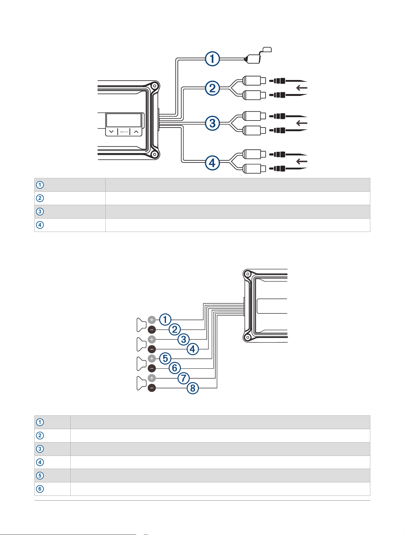
Power Wiring
2
JL Audio® AP Amplifiers
Installation Instructions
1
+12V DC (Red)+
2
Ground (Black)-
3
Remote in (Blue)+
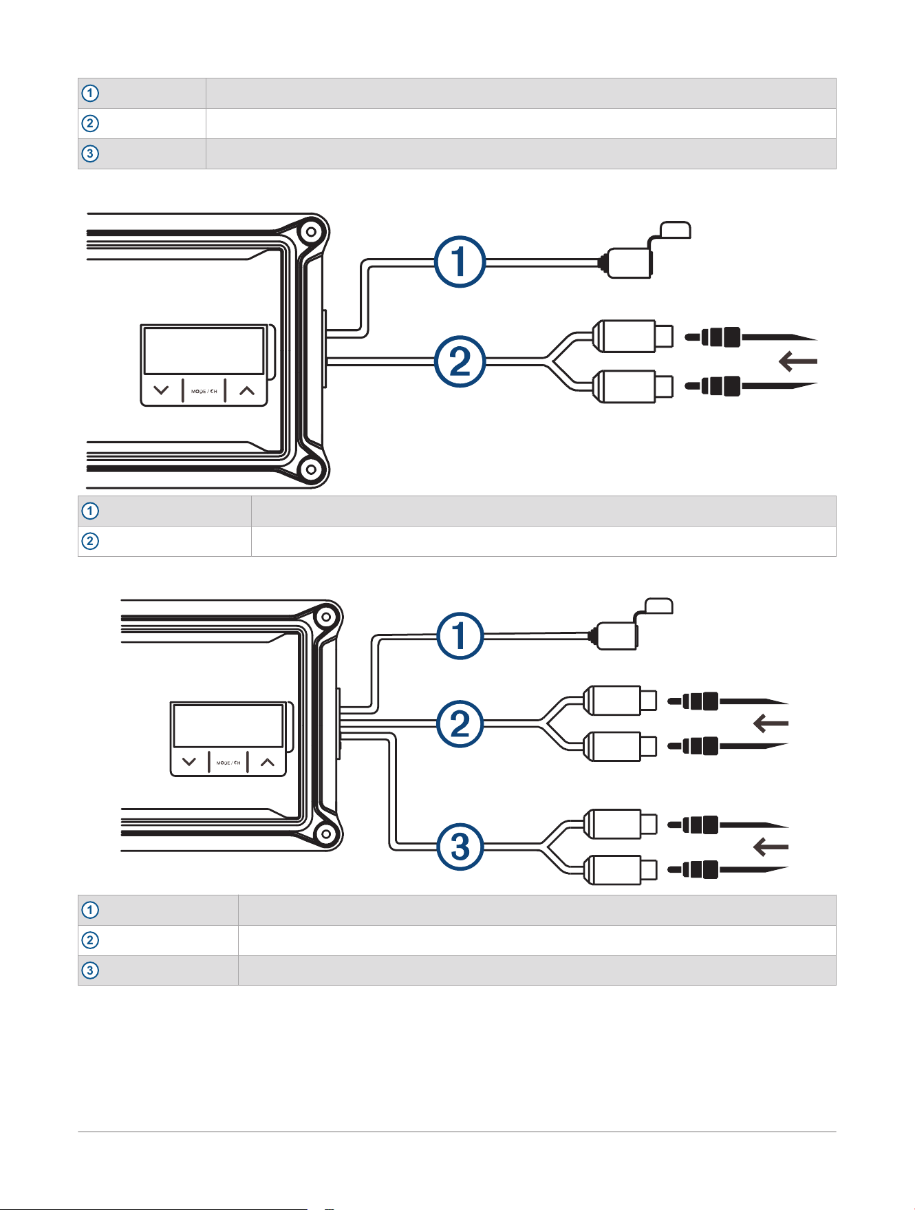
JL Audio
®
AP300/1 Signal Inputs: 200mV - 8V RMS
1
Service port
2
Input
JL Audio
®
AP300/4 Signal Inputs: 200mV - 8V RMS
1
Service port
2
CH. 3/4 input
3
CH. 1/2 input
JL Audio® AP Amplifiers
Installation Instructions
3
JL Audio
®
AP600/6 Signal Inputs: 200mV - 8V RMS
1
Service port
2
CH. 5/6 input
3
CH. 3/4 input
4
CH. 1/2 input
JL Audio
®
AP300/4 Outputs
You can configure the JL Audio AP300/4 in stereo mode or bridged mode, depending on the needs of your
system.
Figure 1: Stereo Mode Outputs
1
CH. 1+ (White)
2
CH. 1- (White with black stripe)
3
CH. 2+ (Gray)
4
CH. 2- (Gray with black stripe)
5
CH. 3+ (Green)
6
CH. 3- (Green with black stripe)
4 JL Audio® AP Amplifiers
Installation Instructions
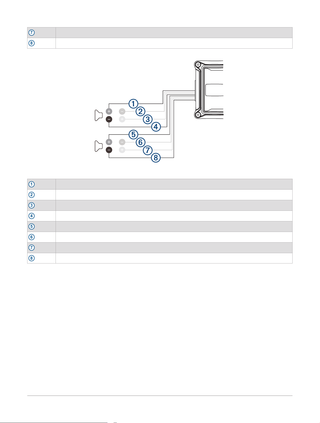
7
CH. 4+ (Violet)
8
CH. 4- (Violet with black stripe)
The minimum impedance for each speaker output in stereo mode is 2 ohms.
Figure 2: Bridged Mode Outputs
1
CH. 1+ (White)
2
unused
3
unused
4
CH. 2- (Gray with black stripe)
5
CH. 3+ (Green)
6
unused
7
unused
8
CH. 4- (Violet with black stripe)
The minimum impedance for each speaker output in bridged mode is 4 ohms.
JL Audio
®
AP600/6 Outputs
You can configure the JL Audio AP600/6 in stereo mode or bridged mode, depending on the needs of your
system.
JL Audio® AP Amplifiers
Installation Instructions
5
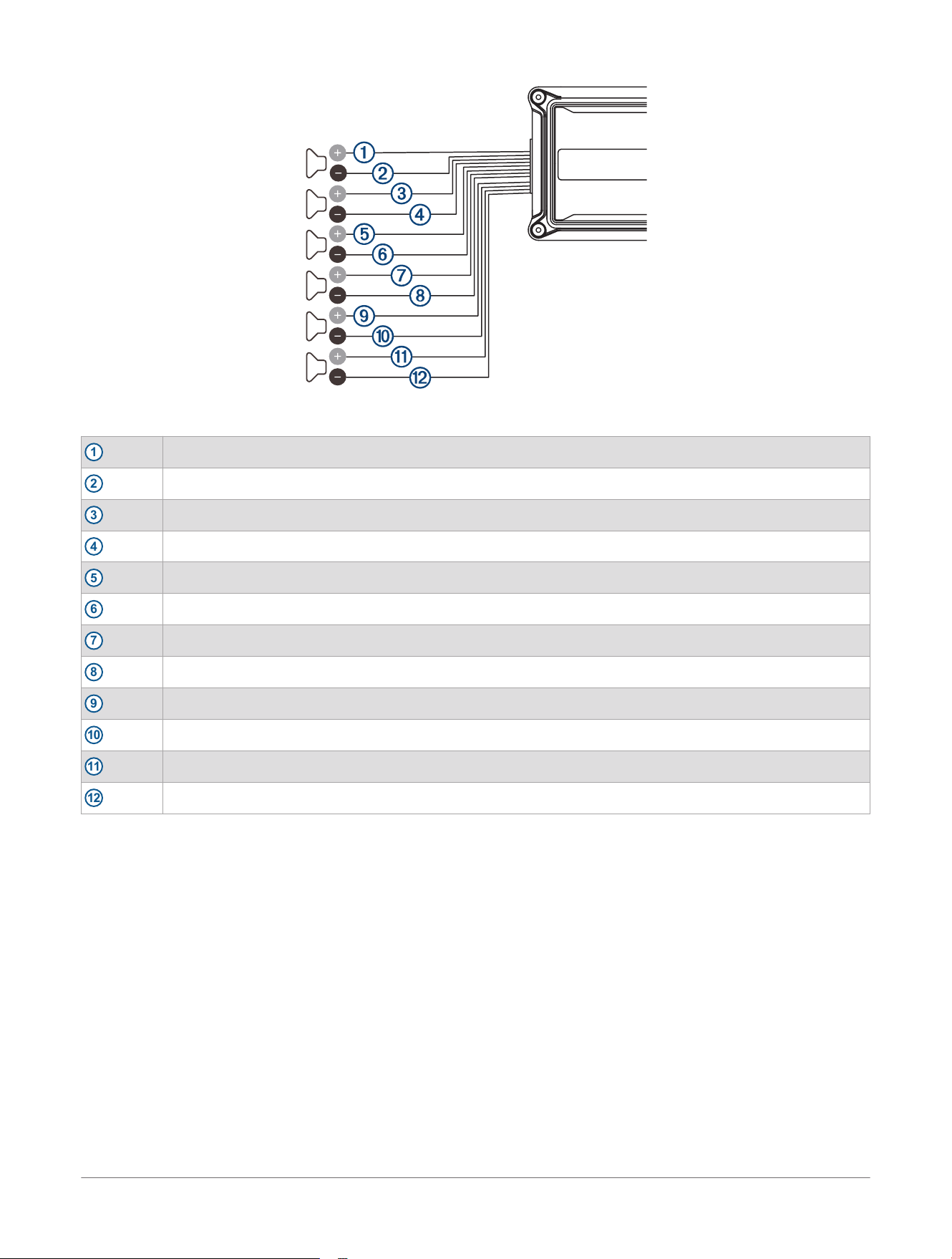
Figure 3: Stereo Mode Outputs
1
CH. 1+ (White)
2
CH. 1- (White with black stripe)
3
CH. 2+ (Gray)
4
CH. 2- (Gray with black stripe)
5
CH. 3+ (Green)
6
CH. 3- (Green with black stripe)
7
CH. 4+ (Violet)
8
CH. 4- (Violet with black stripe)
9
CH. 5+ (Orange)
10
CH. 5- (Orange with black stripe)
11
CH. 6+ (Brown)
12
CH. 6- (Brown with black stripe)
The minimum impedance for each speaker output in stereo mode is 2 ohms.
6
JL Audio® AP Amplifiers
Installation Instructions
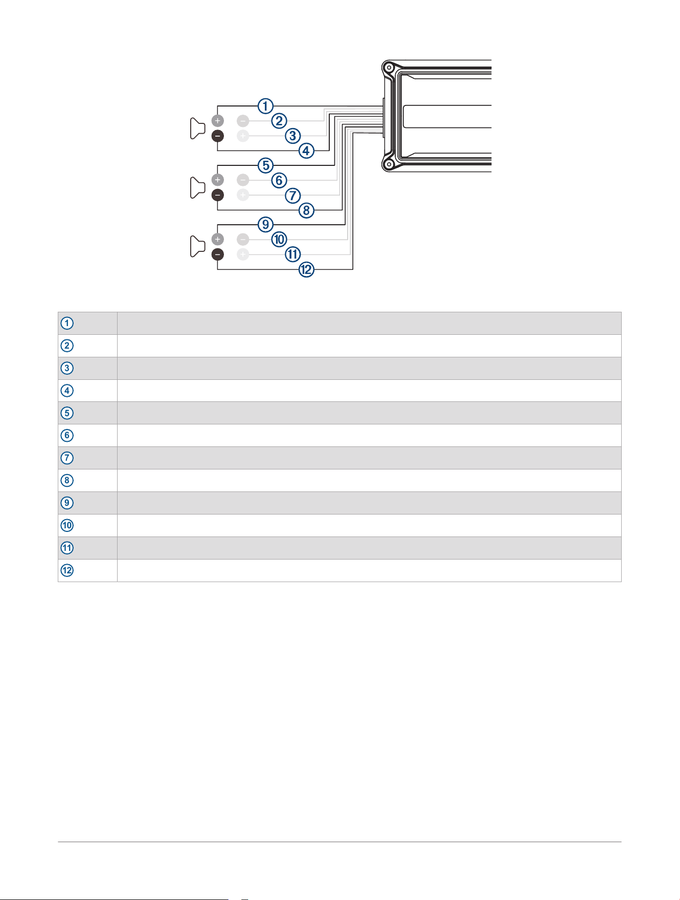
Figure 4: Bridged Mode Outputs
1
CH. 1+ (White)
2
unused
3
unused
4
CH. 2- (Gray with black stripe)
5
CH. 3+ (Green)
6
unused
7
unused
8
CH. 4- (Violet with black stripe)
9
CH. 5+ (Orange)
10
unused
11
unused
12
CH. 6- (Brown with black stripe)
The minimum impedance for each speaker output in bridged mode is 4 ohms.
JL Audio® AP Amplifiers
Installation Instructions
7
JL Audio
®
AP300/1 Outputs
1
SPK+ (Brown)
2
SPK- (Brown with black stripe)
The minimum impedance for the output is 2 ohms.
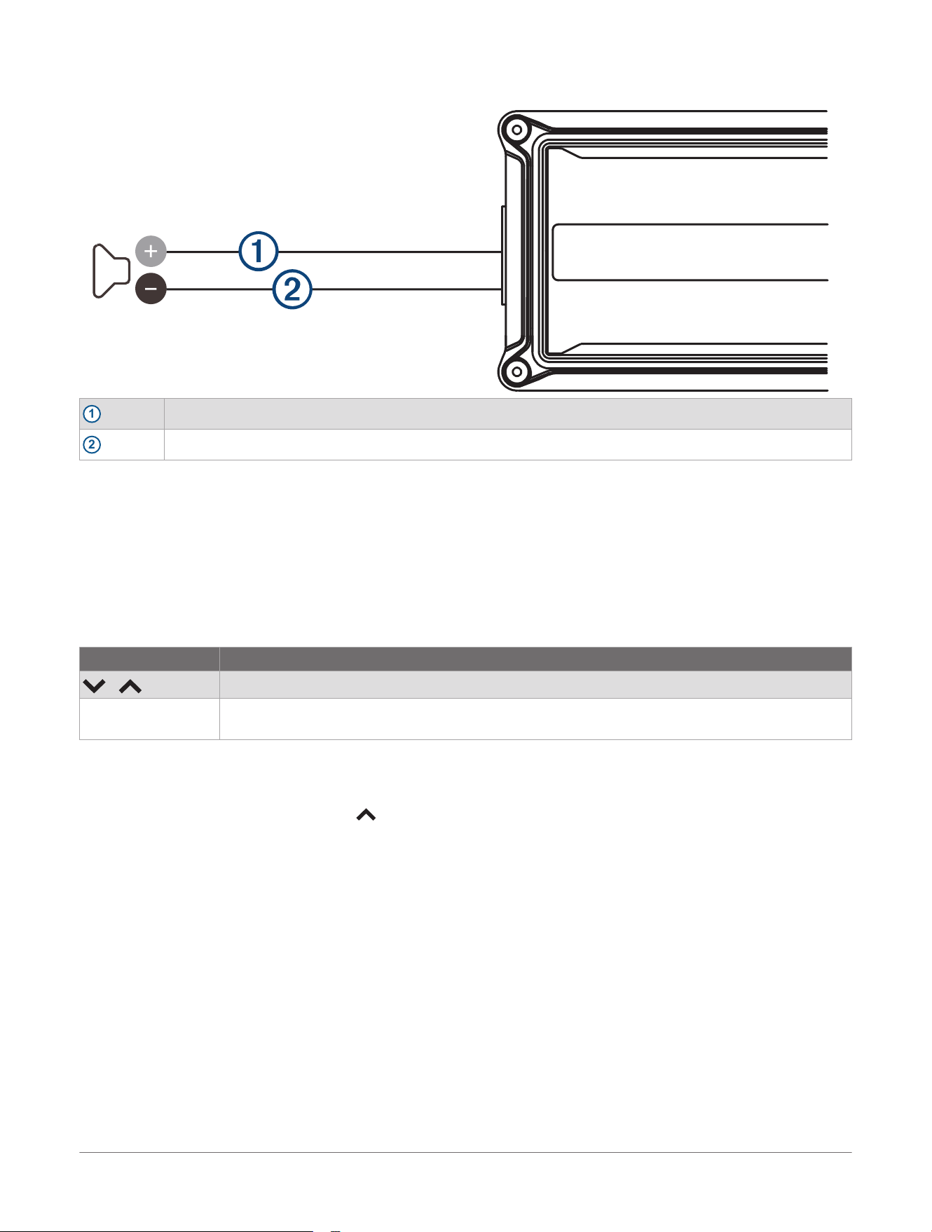
Display and Controls
Default Display
You can configure the amplifier settings using the top-panel display and controls. When the amplifier is on,
the default display alternates between the voltage and internal temperature readings every five seconds. The
default display remains active for sixty seconds before turning off. You can press any button to reactivate the
default display.
Control Description
/
Press to move through the menus
MODE / CH ● Press to enter a selection
● Hold to exit or save and return to the default display
Setup
Changing the Temperature Scale
1 While the default display is on, press to change the temperature reading between Fahrenheit (default) and
Celsius.
2 Hold MODE / CH to save your selection.
Settings
GAIN: (Input Sensitivity) Matches the source unit's output voltage with the inputs of each amplifier or amplifier
pairs from 1 to 11 (default value is 5).
HPF: (High-Pass Filter) For the JL Audio
®
AP300/4 and JL Audio AP600/6, this attenuates frequencies below the
selected filter frequency, from 20 Hz to 500 Hz at a rate of 12 dB per octave (default value is OFF).
LPF: (Low-Pass Filter) Attenuates frequencies above the selected filter frequency, from 20 Hz to 500 Hz at a
rate of 12 dB per octave (default value is 500 Hz).
B.B: (Bass Boost) Equalizer increases the range centered at 37 Hz from 0 to +18 dB (default value is 0).
I.F: (Infrasonic Filter) The JL Audio AP300/1 and CH. 5/6 on the JL Audio AP600/6 include an infrasonic filter.
This setting adjusts the high-pass filter cutoff frequency, from 20 Hz to 50 Hz at a rate of 12 dB per octave
(default value is OFF).
PHASE: (Phase Shift) For the JL Audio AP300/1, this setting inverts the output polarity from 0 (normal) to 180
(inverted) degrees for the best overall bass performance (default value is 0 degrees).
8
JL Audio® AP Amplifiers
Installation Instructions

Changing Settings
1 Press MODE / CH to enter Channel Selection mode.
2 Press or to select a channel pair, and press MODE / CH to confirm.
3 Press or to select a setting, and press MODE / CH to confirm.
4 Press or to adjust a setting.
5 Hold MODE / CH to save and exit.
Easy Tune Mode
The JL Audio
®
AP300/1, JL Audio AP300/4, and JL Audio AP600/6 include an Easy Tune mode that
automatically adjusts the amplifier's settings for use with stereos equipped with DSP profile capabilities or
systems with standalone signal processors. When the amplifier enters Easy Tune mode, the amplifier buttons
become locked and inoperable until Easy Tune mode is turned off.
Using Easy Tune Mode
● To activate Easy Tune mode, hold MODE / CH for 15 seconds.
When Easy Tune mode is activated, the screen displays "Easy Tune" for 60 seconds.
● To turn off Easy Tune mode, hold MODE / CH for 15 seconds.
Changing the Input Sensitivity
You can choose between two input sensitivity ranges on your amplifier. The LOW range (default) is between
200mV and 2V RMS and the HIGH range is between 800 mV and 8V RMS.
1 Press while the default display is on to select an input sensitivity range.
2 Hold MODE / CH to save your selection.
Manually Setting the Input Sensitivity Level
NOTICE
Follow this process only if you are not using the Easy Tune Mode of the amplifier.
Do not increase the GAIN settings in the system beyond the maximum level established during this procedure.
Doing so will result in audible distortion and possible speaker damage.
You must readjust the GAIN settings if any equalizer boost is activated after setting the GAIN with this
procedure. This applies to any EQ boost circuit, including source unit tone controls or EQ circuits. EQ cuts
do not require readjustment.
Required Equipment
● Digital AC voltmeter
● Sine wave test tone recorded at 0 dBFS reference level in the frequency range to be amplified.
Do not use attenuated test tones (such as -10 dB or -20 dB).
Full range channel/amplifier applications (JL Audio
®
AP300/4 and JL Audio AP600/6): 1 kHz
Subwoofer channel/amplifier applications: 50 Hz
● Depending on your type of source unit, the sine wave may be played from a CD, USB thumb drive, or a
portable media player. You must disable any EQ/DSP modes on your portable media player during level
setting.
Follow these steps to adjust the input sensitivity of each amplifier channel or channel pair to achieve overall
system balance.
1 Disconnect the speakers from the amplifier's speaker output connectors.
2 Turn off all processing (bass/treble, loudness, EQ, etc.) on the source unit, processors (if used) and
amplifier.
3 Set all of the fader control to the center position, and set the subwoofer level control to
3
/
4
of maximum, if
used.
4 Set all of the GAIN controls to "1".
5 Set the source unit volume to
3
/
4
of full volume to allow for reasonable gain overlap with moderate clipping
at full volume.
6 Determine the target AC voltage for input sensitivity adjustment according to the nominal impedance of the
speaker system connected to the amplifier outputs (Target AC Voltage, page10).
7 Verify that you have disconnected the speakers before proceeding.
JL Audio® AP Amplifiers
Installation Instructions
9

8 Play a track with an appropriate sine wave (within the frequency range to be amplified) at
3
/
4
source unit
volume.
9 Connect the AC voltmeter to the speaker output terminals of the amplifier.
For the JL Audio AP300/4 or JL Audio AP600/6, if the channel pair is operating in stereo, it is only
necessary to measure one channel. If bridged, you must test the voltage at the correct terminals (L+ and
R-).
10 While observing the voltmeter, adjust the GAIN control to a setting closest to the target AC voltage.
11 After you have adjusted each source/channel section to its maximum low-distortion output level, reconnect
the speakers.
You can adjust the GAIN controls downward if the amplifier requires attenuation to achieve the desired system
balance.
Checking the Firmware Version
Hold MODE / CH and simultaneously for three seconds.
The amplifier displays the current firmware version.
Restoring All Default Settings
Hold and simultaneously for seven seconds.
After seven seconds, all settings are returned to their original factory default values and FACT appears on the
screen.
Protection Mode
The amplifier includes built-in features to monitor for thermal and short circuit fault conditions.
Display Function
TEMP Indicates thermal fault (over-temperature condition).
● The audio output is muted.
● The amplifier returns to normal operation when the temperature returns to a safe level.
PROT Indicates an over-current condition.
● The audio output is muted and the audio may exhibit a repetitive, audible ticking or thumping noise in the
output.
● Possible causes include a speaker impedance lower than the optimum load range or a short-circuit in the
speaker wiring. A short circuit can be between the positive and negative speaker wires or between either
speaker wire and the vehicle chassis or +12V.
● The amplifier returns to normal operation when impedance returns to safe level. Some incidents may
require you to restart the amplifier.
Appendix
Target AC Voltage
JL Audio
®
AP300/1 Target AC Voltage
Nominal Impedance
4 ohms 28.3 V
2 ohms 24.5 V
JL Audio AP300/4 Target AC Voltage
Nominal Impedance Stereo (CH. 1/2/3/4) Bridged (CH. 1/2/3/4)
4 ohms 14.1 V 24.5 V
2 ohms 12.2 V not recommended
10 JL Audio® AP Amplifiers
Installation Instructions

JL Audio AP600/6 Target AC Voltage
Nominal
Impedance
Stereo (CH.
1/2/3/4)
Stereo (CH. 5/6) Bridged (CH.
1/2/3/4)
Bridged (CH. 5/6)
4 ohms 14.1 V 20.0 V 24.5 V 34.6 V
2 ohms 12.2 V 17.3 V not recommended not recommended
Specifications
All Models
Amplifier Topology Class D
Power Supply Type Regulated MOSFET switching
Operating Voltage 14.4V DC (9V to 16V)
Operating Temperature From -20 to 65°C (from -4 to 149°F)
Storage Temperature From -40 to 85°C (from -40 to 185°F)
Minimum Copper Power/GND Wire 4 AWG
NOTE: Copper clad aluminum (CCA) wire is not recommended.
S/N Ratio (A-weighted, 20 Hz to 20 kHz noise
bandwidth)
>70 dB (Referred to 1W)
Water Rating
IEC 60529 IP67
1
Type Preamp RCA jacks
Input Voltage Range 200mV to 2V RMS (low) or 800mV to 8V RMS (high)
Bass Boost EQ 0 to +18 dB, centered at 37 Hz, always active
JL Audio
®
AP300/1 Specifications
Recommended Fuse 35 A
Rated RMS Power @ 14.4V, <1% THD+N 200W x 1 @ 4 ohms
300W x 1 @ 2 ohms
Frequency Response 10 Hz to 500 Hz (+0, -3 dB)
Speaker Quantity One stereo pair
Filter Type Active, 12 dB/octave, low-pass (20 Hz to 500 Hz)
Infrasonic Filter 20 Hz to 50 Hz, 12 dB/octave
Phase Shift 0 to 180 degrees
Amplifier Dimensions ( L x W x H) 265 x 125 x 47 mm (10.43 x 4.90 x 1.85 in.)
JL Audio AP300/4 Specifications
Recommended Fuse 35 A
Rated RMS Power @ 14.4V, <1% THD+N 50W x 4 @ 4 ohms
75W x 4 @ 2 ohms
150W x 2 @ 4 ohms bridged
Frequency Response 20 Hz to 20 kHz (+0, -3 dB)
Speaker Quantity Two stereo pairs
Filter Type Active, 12 dB/octave, high-pass or low-pass (20 Hz to 500 Hz), defeatable
Infrasonic Filter N/A
Phase Shift N/A
Amplifier Dimensions ( L x W x H) 265 x 125 x 47 mm (10.43 x 4.90 x 1.85 in.)
1
The device is protected against the ingress of dust and withstands incidental exposure to water of up to 1 m for up to 30 min. For more information,
go to , .
JL Audio® AP Amplifiers
Installation Instructions
11
JL Audio AP600/6 Specifications
Recommended Fuse 70 A
Rated RMS Power @ 14.4V, <1% THD+N CH. 1/2/3/4:
50W x 4 @ 4 ohms
75W x 4 @ 2 ohms
150W x 2 @ 4 ohms bridged
CH. 5/6:
100W x 2 @ 4 ohms
150W x 2 @ 2 ohms
300W x 1 @ 4 ohms bridged
Frequency Response 20 Hz to 20 kHz (+0, -3 dB)
Speaker Quantity Three stereo pairs
Filter Type Active, 12 dB/octave, high-pass or low-pass
(20 Hz to 500 Hz), defeatable
Infrasonic Filter 20 Hz to 50 Hz, 12 dB/octave (CH. 5/6 only)
Phase Shift N/A
Amplifier Dimensions ( L x W x H) 300 x 150 x 47 mm (11.81 x 5.90 x 1.85 in.)
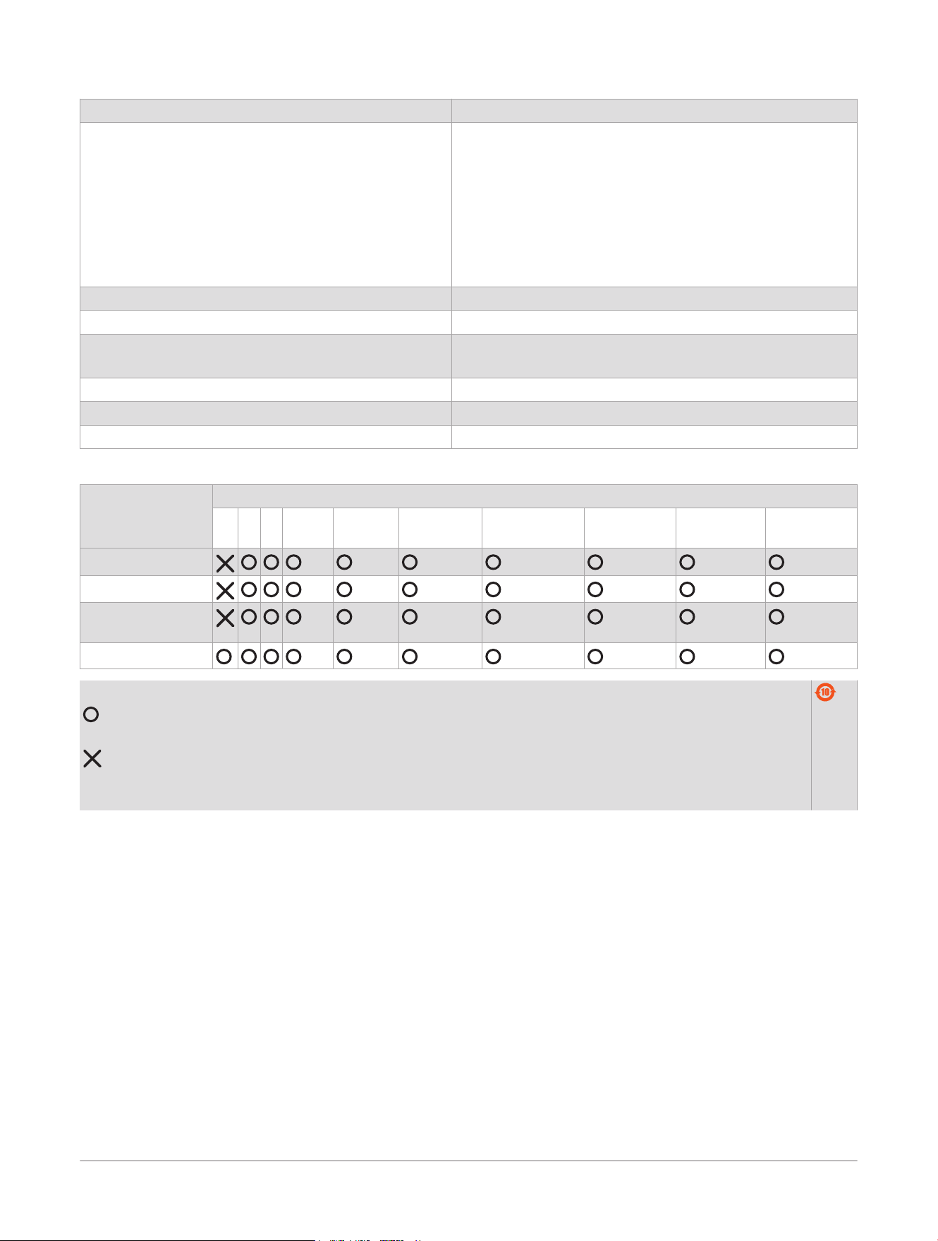
物質宣言
部件名称 有毒有害物质或元素
铅 汞 镉 六价铬 多溴联苯 多溴二苯
醚
邻苯二甲酸二
(2-乙基己)酯
邻苯二甲酸
丁苄酯
邻苯二甲酸
二丁酯
邻苯二甲酸
二异丁酯
印刷电路板组件
金属零件
电缆 电缆组件 连接
器
塑料和橡胶零件
本表格依据 SJ/T11364 的规定编制。
: 代表此种部件的所有均质材料中所含的该种有害物质均低于
(GB/T26572) 规定的限量
: 代表此种部件所用的均质材料中, 至少有一类材料其所含的有害物质高于
(GB/T26572) 规定的限量
* 该产品说明书应提供在环保使用期限和特殊标记的部分详细讲解产品的担保使用条件。
产品
© 2025 Garmin Ltd. or its subsidiaries
Garmin
®
, the Garmin
®
logo, JL Audio
®
, and the JL Audio
®
logo are trademarks of Garmin Ltd. or its subsidiaries, registered in the USA and other countries.
These trademarks may not be used without the express permission of
Garmin
®
.
M/N: A0P2895, A0P2896, A0P2897
12
JL Audio® AP Amplifiers
Installation Instructions