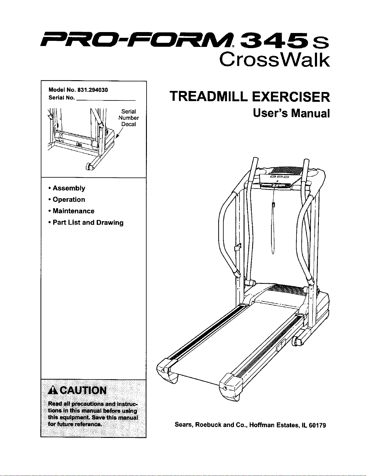
r"_n"__-____. 3 4 5 s
CrossWalk
Model No. 831.294030
Serial No.
erial
Number
Decal
• Assembly
• Operation
• Maintenance
• Part List and Drawing
TREADMILL EXERCISER
User's Manual
Sears, Roebuck and Co., Hoffman Estates, IL 60179
___-Fr__M. 3 4 5 s
CrossWalk
TABLE OF CONTENTS
IMPORTANT PRECAUTIONS ................................................................ 3
BEFORE YOU BEGIN ...................................................................... 5
ASSEMBLY ............................................................................... 6
OPERATION AND ADJUSTMENT ............................................................ 10
HOW TO FOLD AND MOVE THE TREADMILL .................................................. 14
TROUBLESHOOTING ..................................................................... 16
CONDITIONING GUIDELINES ............................................................... 18
ORDERING REPLACEMENT PARTS .................................................. Back Cover
FULL 90 DAY WARRANTY .......................................................... Back Cover
Note: An EXPLODED DRAWING and a PART LIST are attached in the center of this manual.
2
IMPORTANT PRECAUTIONS
i!i!iiiiii_iiii
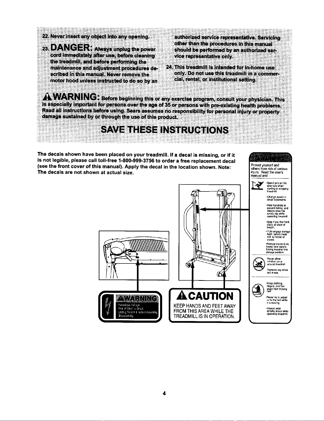
The decals shown have been placed on your treadmill. If a decal is missing, or if it
is not legible, please call toll-free 1-800-999-3756 to order a free replacement decal
(see the front cover of this manual). Apply the decal in the location shown. Note:
The decals are not shown at actual size.
[ ACAUTII N ]
KEEPHANDSANDFEETAWAYI
FROMTHISAREAWHILETHE |
TREADMILLISINOPERATION.J
Protect yourseff and
others from risk of sedous
injury. Read the user's
manual and :
i'_ *Sland Only Onthe
Side rails w_en
starting or stopping
treadmill
•Chan e sp_erhn
small _ncre'nen s
,HoW handrai_lo
preventfallins, and
always wear(he
safe_ clip while
opera_ng lreadmiil
,St_o if yo_ feel faint,
dizzy, et short of
I_eatn
• Fully e_gage storage
I_Ch bef_e tre_d-
mill is mow_ or
stored¸
•Redu_:e incline Ir_its
_owest _evel before
f_d_ng _readmlllinro
s_oragepo,s_n
_d h'e_m_l
_ lir_ers, and hai r
_,_ay from moving
,Never I1"/to _lju_l
_l is moving
•Al_ays _at
athl_ _loes While
_p_atitlg IreadmiH
4
BEFORE YOU BEGIN
Thank you for selectingthe revolutionaryPROFORM ®
CROSSWALK 345s treadmill. The CROSSWALK 345s
treadmillcombines advancedtechnologywith innova-
tive designto helpyou get the most from your exercise
programinthe convenience and privacyof your home.
And when you'renotexercising,the uniqueCROSS-
WALK 345s treadmillcan be folded up, requiringless
than halfthe floor space ofother treadmills.
For your benefit, read this manual carefully before
using the treadmill. Ifyou have questionsafter reading
this manual,call 1-800-.4-MY-HOME®(1-800-469-
4663).To helpus assist you, pleasenotethe product
modelnumber and serialnumberbeforecalling.The
modelnumber ofthe treadmillis831.294030. The sedal
numbercanbe found ona decal attachedto the tread-
mill(see the front coverofthismanualfor the location).
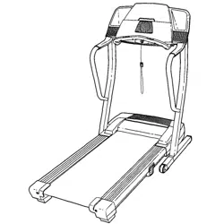
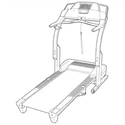
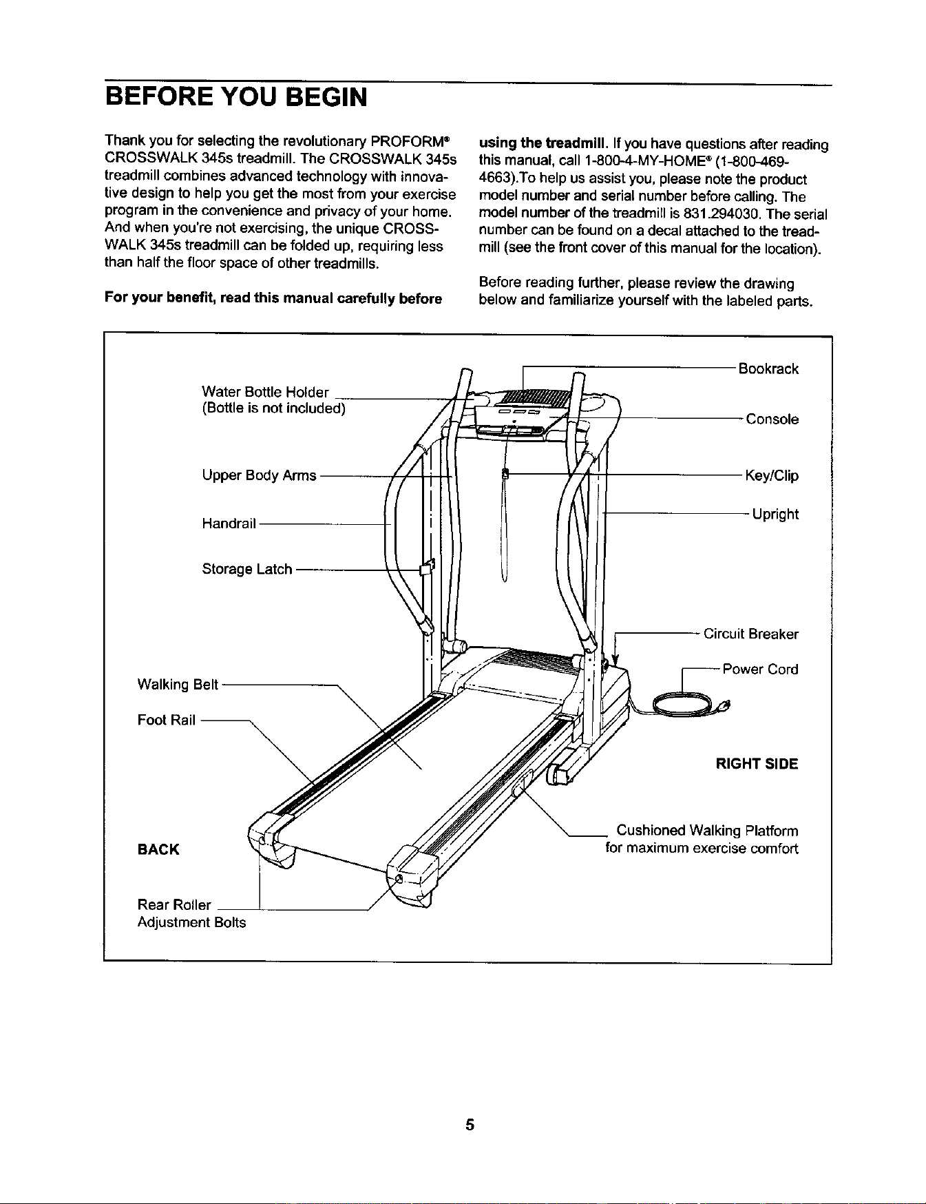
Beforereading further, please review the drawing
below and familiarize yourself with the labeled parts.
Water Bottle Holder
(Bottle is not included)
Upper BodyArms
Handrail
Storage Latch
Bookrack
Console
Key/Clip
Upright
- Circuit Breaker
Walking Belt
\
RIGHT SIDE
BACK
--. Cushioned Walking Platform
for maximum exercise comfort
Rear Roller
Adjustment Bolts
5
ASSEMBLY
Assembly requires two persons. Set thetreadmill in a cleared area and removeall packing materials.Do not
disposeofthe packingmaterialsuntilassembly is completed.
Note: The undersideof the treadmill walking belt is coated with high-performance lubdcant. During shipping, a
small amount of lubricant may be transferred to the top of the walking belt or the shipping carton. This is a normal
condition and does not affect treadmill performance. If there is lubricant on top of the walking belt, simply wipe off
the lubricantwith a soft cloth and a mild, non-abrasive cleaner.
Assembly requires the included allen wr_ and your own phillips screwdriver (_=====-,
rubber mallet _ , wire cutters _, and needlenose pliers _E]_,,.
For help identifying the assembly hardware, see the drawings below. Note: The assembly hardware and
other small parts are packaged in separate part bags. Do not open the part bags until instructed to do so.
Ifa part is notin the parts bag, firstcheck to see if it has been pre-assembled, If a part is missing, call toll-free
1-800-999-3756.
3/4"Tek Screw (58)-8
3/4" Bolt (37)-6
1" Screw (99)-2
1/2"Silver Screw
(48)-1
3/4" Screw (2)-6
D©
Washer (38)-6
1/2" GroundScrew
(75)-1
Wheel Nut (32)-2
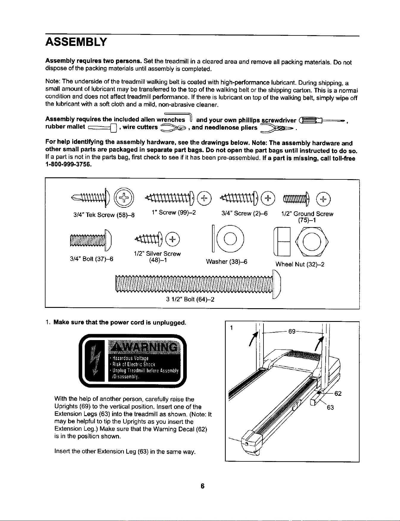
1. Make sure that the power cord is unplugged.
With the help of another person, carefully raise the
Uprights (69) to the vertical position. Insert one of the
Extension Legs (63) into the treadmill as shown. (Note: It
may be helpful to tip the Uprights as you insert the
Extension Leg.) Make sure that the Warning Decal (62)
is in the position shown.
Insert the other Extension Leg (63) in the same way.
-62
63
6
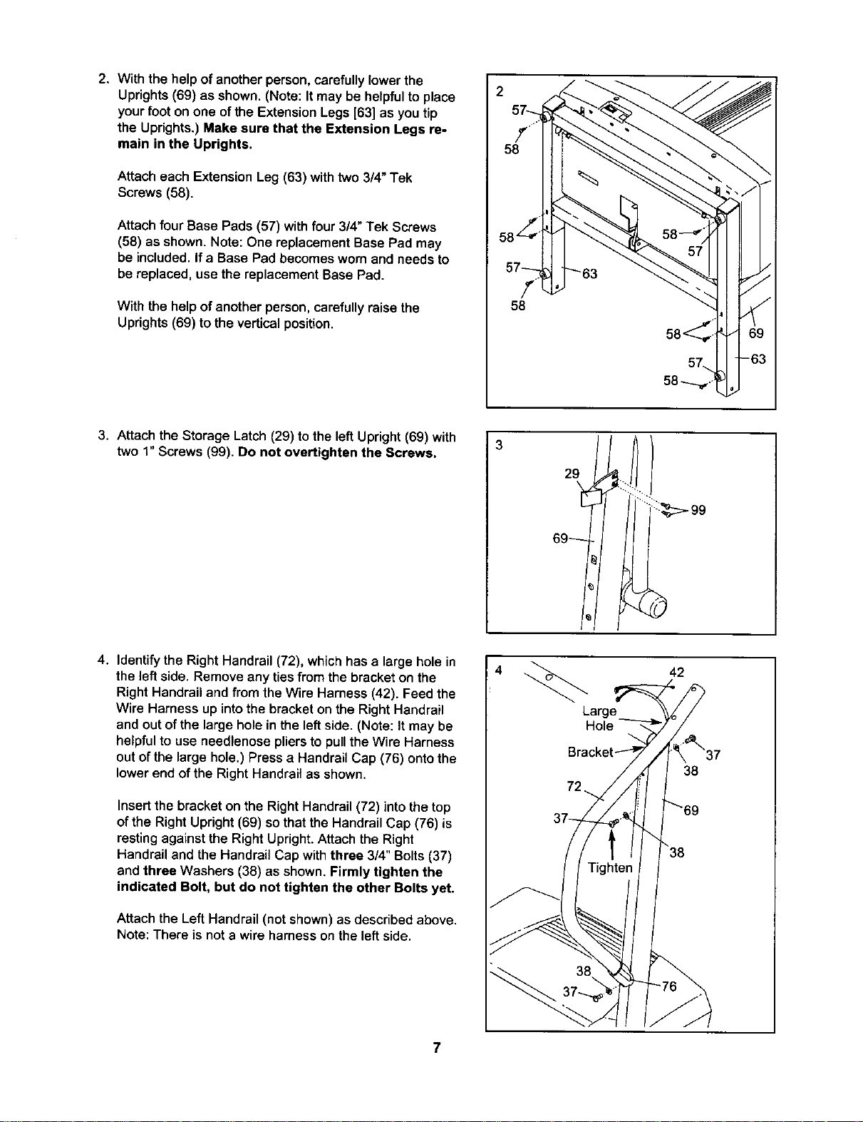
2. With the help of another person, carefully lower the
Uprights (69) as shown. (Note: It may be helpful to place
your foot on one of the Extension Legs [63] as you tip
the Uprights.) Make sure that the Extension Legs re-
main in the Uprights,
Attach each Extension Leg (63) withtwo 3/4" Tek
Screws (68).
Attach four Base Pads (57) withfour3/4" Tek Screws
(58) as shown. Note: One replacement Base Pad may
be included.If a Base Pad becomesworn and needs to
be replaced, use the replacement Base Pad.
With the help of another person, carefully raise the
Uprights (69) to the vertical position.
2
f
58
68, II
58
3. Attach the Storage Latch (29) to the left Upright (69) with
two 1" Screws (99). Do not overtighten the Screws.
3
4. Identify the Right Handrail (72), whichhas a large hole in
the left side. Remove any ties from the bracket on the
Right Handrail and from the Wire Harness (42). Feed the
Wire Harness up into the bracket on the Right Handrail
and out of the large hole in the left side. (Note: It may be
helpful to use needlenose pliers to pull the Wire Harness
out of the large hole.) Press a Handrail Cap (76) onto the
lower end of the Right Handrail as shown.
Insertthe bracket on the Right Handrail (72) into the top
of the Right Upright (69) so that the Handrail Cap (76) is
resting against the Right Upright. Attach the Right
Handrail and the Handrail Cap with three 3/4" Bolts (37)
and three Washers (38) as shown. Firmly tighten the
indicated Bolt, but do not tighten the other Bolts yet.
Attach the Left Handrail (not shown) as described above.
Note: There is not a wire harness on the left side.
4
42
38
7
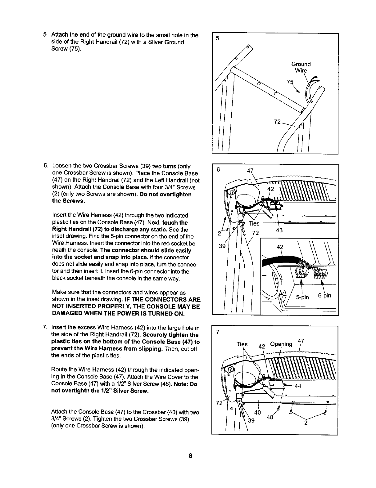
5. Attach the end ofthe groundwire to the small hole in the
side of the Right Handrail(72) with a SilverGround
Screw (75).
5
Ground
Wire
\
6. Loosenthe two Crossbar Screws (39) two turns (only
one Crossbar Screwis shown). Place the Console Base
(47) on the RightHandrail (72) and the Left Handrail (not
shown).Attach the Console Basewithfour 3/4" Screws
(2) (onlytwo Screws are shown). Do not overtighten
the Screws.
Insert theWire Harness (42) through the two indicated
plasticties on theConsoleBase (47). Next, touch the
Right Handrail (72) to discharge any static. See the
insetdrawing.Findthe 5-pinconnectoronthe end ofthe
Wire Harness. Inserttheconnectorintothe red socketbe-
neaththeconsole.The connector should slide easily
intothe socket and snap into place. If the connector
does notslideeasilyand snapintoplace,turnthe connec-
torand then insertit.Insertthe 6-pin connectorintothe
blacksocketbeneaththe consolein the sameway.
Make sure that the connectors and wires appear as
shown in the inset drawing. IF THE CONNECTORS ARE
NOT INSERTED PROPERLY, THE CONSOLE MAY BE
DAMAGED WHEN THE POWER IS TURNED ON.
7. Insert the excess Wire Harness (42) into the large hole in
the side of the Right Handrail (72). Securely tighten the
plastic ties on the bottom of the Console Base (47) to
prevent the Wire Harness from slipping. Then, cut off
the ends of the plastic ties.
Route the Wire Harness (42) throughthe indicatedopen-
ing in the Console Base (47). Attach the Wire Cover to the
Console Base (47) with a 1/2" Silver Screw (48). Note: Do
not overtightn the 1/2" Silver Screw.
Attach the Console Base (47) tothe Crossbar (40) withtwo
3/4" Screws (2). Tighten the two Crossbar Screws (39)
(only one Crossbar Screw is shown).
6 47
72 43
5-pin 6-pin
7
Ties 42
47
7;
® 40 48J :' "
I 2
8
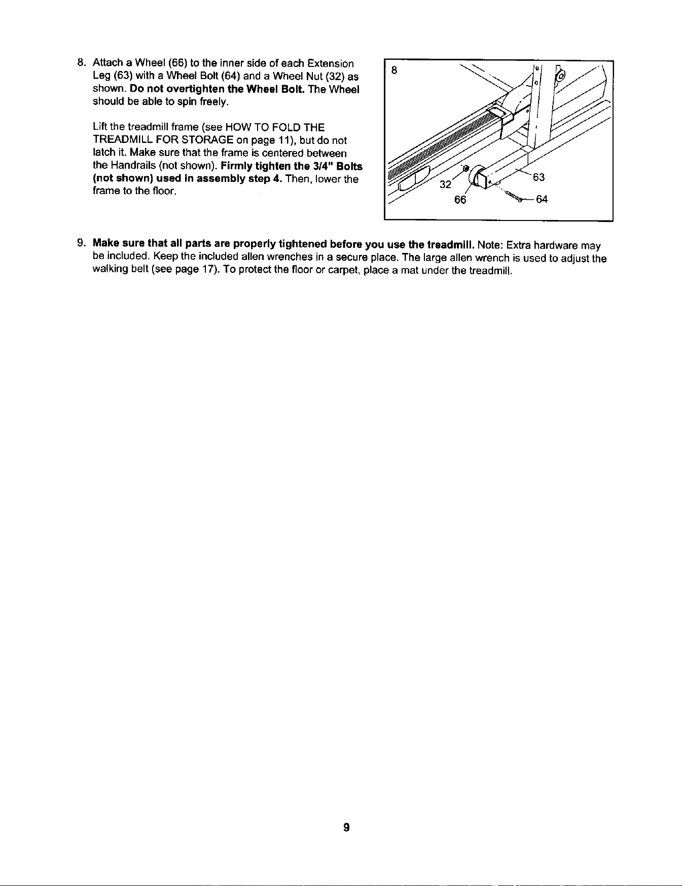
8. Attacha Wheel (66) to the inner side of each Extension
Leg (63) with a Wheel Bolt (64) and a Wheel Nut (32) as
shown. Do not overtighten the Wheel Bolt. The Wheel
shouldbe able to spin freely.
Lift the treadmill frame (see HOW TO FOLD THE
TREADMILL FOR STORAGE on page 11), but do not
latch it. Make sure that the frame is centered between
the Handrails (not shown). Firmly tighten the 314" Bolts
(not shown) used in assembly step 4. Then, lower the
frame tothe floor.
9. Make sure that all parts are properly tightened before you use the treadmill. Note: Extra hardware may
be included. Keep the included allen wrenches in a secure place. The large allen wrench is used to adjust the
walking belt (see page 17). To protect the floor or carpet, place a mat under the treadmill.
9
OPERATION AND ADJUSTMENT
THE PERFORMANT LUBETM WALKING BELT
Your treadmillfeatures a walking belt coated with
PERFORMANT LUBETM, a high-performance lubricant.
IMPORTANT; Never apply silicone spray or other
substances to the walking belt or the walking plat-
form. Such substances will deteriorate the walking
belt and cause excessive wear.
HOWTO PLUG IN THE POWER CORD
Your treadmill, like any other type ofsophisticated
electronicequipment, can be seriouslydamaged by
sudden voltagechanges in your home's power.
Voltage surges, spikes,and noise interferencecan
resultfrom weather conditionsor fromotherappliances
being turned on or off. To decrease the possibility of
your treadmill being damaged, always use a surge
suppressor with your treadmill (see drawing 1 at
the right). To purchase a surge suppressor, see
your local Sears or call 1-800-366-7278 and order
part number 146148.
Use only a single-outlet surge suppressor that is
UL 1449 listed as a transient voltage surge sup-
pressor (TVSS). The surge suppressor must have a
UL suppressed voltage rating of 400 volts or less
and a minimum surge dissipation of 450 joules.
The surge suppressor must be electrically rated
for 120 volts AC and 15 amps. There must be a
monitoring light on the surge suppressor to indi-
cate whether it is functioning properly. Failure to
use a properly functioning surge suppressor could
result in damage to the control system of the
treadmill. If the control system is damaged, the
walking belt may change speed or stop unexpect-
edly, which may result in a fall and serious injury.
This product must be grounded. If it should malfunc-
tion or break down, grounding provides a path of least
resistance for electric current to reduce the risk of elec-
tric shock. This product is equipped with a cord having
an equipment-groundingconductor and a grounding
plug. Plug the power cord into a surge suppressor,
and plug the surge suppressor into an appropriate
outlet that is properly installed and grounded in
accordance with all local codes and ordinances.
Important: The treadmill is not compatible with
GFCl-equipped outlets.
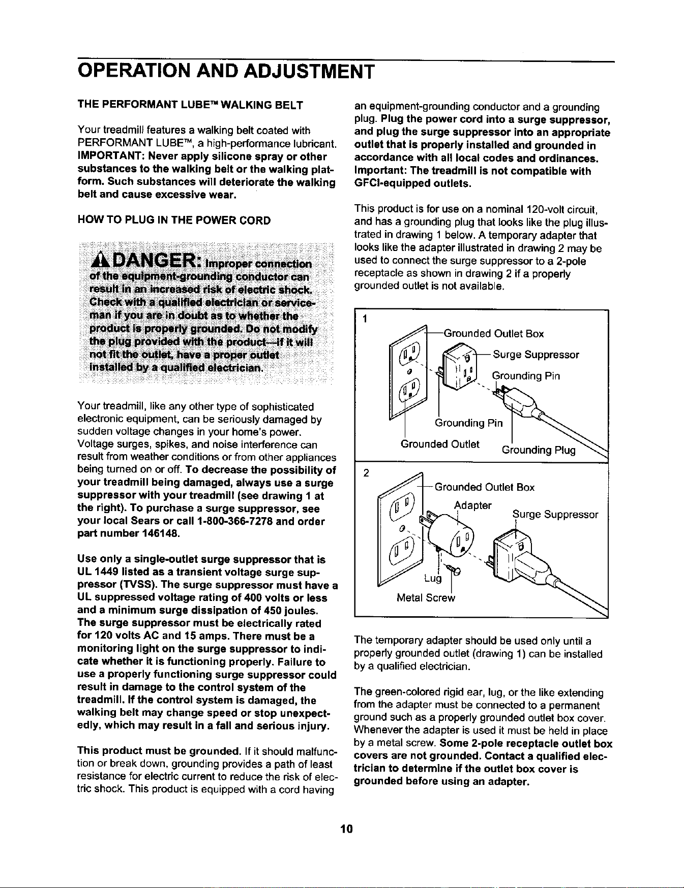
This product is for useon a nominal 120-voltcircuit,
and hasa groundingplugthat lookslike the plugillus-
trated in drawing 1 below. A temporaryadapter that
lookslikethe adapter illustratedin drawing2 may be
used to connectthe surgesuppressorto a 2-pole
receptacleas shown indrawing 2 if a propedy
groundedoutletis notavailable.
2
Grounded Outlet Box
_'-1 ._ Surge Suppressor
_" _... Grounding Pin
Grounding Pin
Grounded Outlet Grounding Plug
¢€_Grounded Outlet Box
Adapter ^
( _J _%_'_1 Surge suppressor
The temporary adapter should be used onlyuntila
properly grounded outlet (drawing 1) can be installed
bya qualifiedelectrician.
The green-colored rigid ear, lug, orthe likeextending
from the adapter must be connected to a permanent
ground such as a properly grounded outlet box cover.
Whenever the adapter is used it must be held in place
bya metal screw. Some 2-pole receptacle outlet box
covers are not grounded. Contact a qualified elec-
trician to determine if the outlet box cover is
grounded before using an adapter.
10
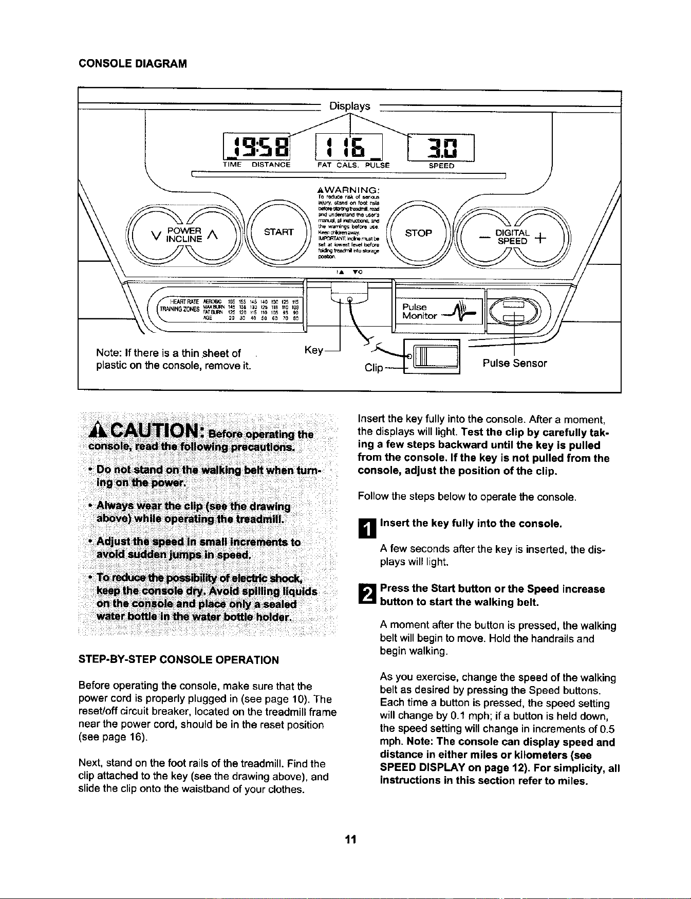
CONSOLE DIAGRAM
STEP-BY-STEP CONSOLE OPERATION
Before operating the console, make sure that the
power cord is properly plugged in (see page 10). The
reset/off circuitbreaker, locatedon the treadmillframe
near the powercord, should be in the reset position
(see page 16).
Next, stand on the foot rails of the treadmill. Find the
clip attached to the key (see the drawing above), and
slide the clip onto the waistband of your clothes.
Insert the key fully into the console. After a moment,
the displays will light. Test the clip by carefully tak-
ing a few steps backward until the key is pulled
from the console. If the key is not pulled from the
console, adjust the position of the clip,
Follow the steps below to operate the console.
_! Insert the key fully into the console.
A few seconds after the key is inserted, the dis-
playswilllight.
B Press the Start button or the Speed increase
button to start the walking belt.
A moment after the button is pressed, the walking
belt will begin to move. Hold the handrails and
begin walking.
As you exercise, change the speed ofthe walking
belt as desired by pressing the Speed buttons.
Each time a button is pressed, the speed setting
will change by 0.1 mph; ifa button is held down,
the speed setting will change in increments of 0.5
mph.Note: The console can display speed and
distance in either miles or kilometers (see
SPEED DISPLAY on page 12), For simplicity, all
instructions in this section refer to miles.
11
To stopthe walking belt, press the Stop button.
The elapsedtime will begin to flash inthe
Time/Distancedisplay.
Note: Duringthe first few minutes that thetreadmill
is used, inspect the alignment of the walking belt,
and align it if necessary (see page 16).
I_1 Change the incline of the treadmill as desired.
To changethe incline of the treadmill, presseither
of the Inclinebuttonsuntilthe desired inclinelevel
is reached,
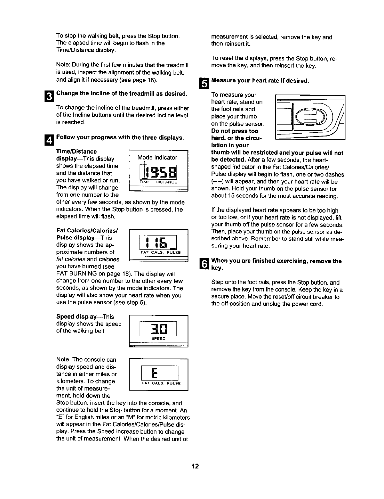
B Follow your progress with the three displays.
TimelDistance
display--This display
showsthe elapsedtime
and the distancethat
you have walked or run.
The displaywillchange
from one number tothe
Mode Indicator
F 81
TIME DISTANCE
other every few seconds, as shown by the mode
indicators.When the Stop button is pressed, the
elapsed time will flash.
Fat CalorieslCalories/
Pulse display--This ]display shows the ap- 1 l_il_
proximate numbers of FATCALS,PULSE
fat calories and calories
you have burned (see
FAT BURNING on page 18). The display will
change from one number to the other every few
seconds, as shown by the mode indicators. The
display will also show your heart rate when you
use the pulse sensor (see step 5).
Speed display--This
display shows the speed
of the walking belt [ 3.-.]
SPEED
Note: The console can
display speed and dis- [ E ]
tance in either miles or
kilometers. To change FAT CALS PULSE
the unit of measure-
ment, hold down the
Stop button, insert the key into the console, and
continue to hold the Stop button for a moment, An
"E" for English miles or an "M" for metric kilometers
will appear in the Fat Calories/Calories/Pulse dis-
play. Press the Speed increase button to change
the unit of measurement. When the desired unit of
measurement is selected, remove the key and
then reinsert it.
To resetthe displays, press the Stop button, re-
movethe key, andthen reinsert the key.
B Measure your heart rate if desired.
To measure your
heart rate, standon
thefoot rails and
place yourthumb
on the pulsesensor.
Do not press too
hard, or the circu-
lation in your
thumb will be restricted and your pulse will not
be detected. After a few seconds,the heart-
shapedindicatorin the Fat Calories/Calories/
Pulse displaywillbeginto flash, one or two dashes
(- -) will appear, and then your heart rate will be
shown.Hold yourthumb onthe pulse sensorfor
about 15 secondsfor the mostaccurate reading.
If the displayed heart rate appears to be too high
or too low, or if your heart rate is not displayed, lift
your thumb off the pulse sensor for a few seconds.
Then, place your thumb on the pulse sensor as de-
scribed above. Remember to stand still while mea-
suring your heart rate.
B When you are finished exercising, remove the
key.
Step ontothe foot rails, press the Stop button, and
removethe keyfrom the console. Keep the key in a
secureplace.Move the reset/offcircuitbreaker to
theoff positionand unplugthe power cord.
12
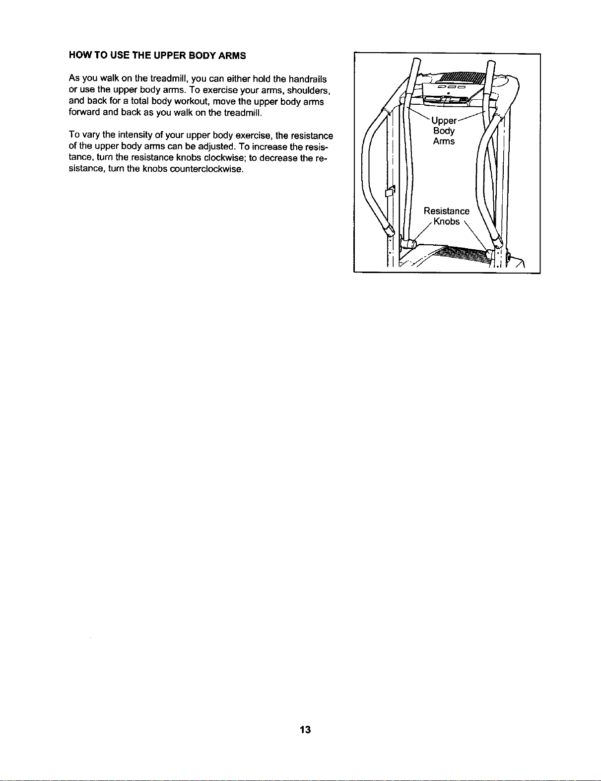
HOW TO USE THE UPPER BODY ARMS
As you walk on the treadmill, you can eitherhold the handrails
or use the upper body arms. To exercise your arms, shoulders,
and back for a total body workout, move the upper body arms
forward and back as you walk on the treadmill.
To vary the intensityofyour upper body exercise, the resistance
of the upper body arms can be adjusted. To increase the resis-
tance, turn the resistance knobs clockwise; to decrease the re-
sistance, turn the knobs counterclockwise.
/
13
HOW TO FOLD AND MOVE THE TREADMILL
HOW TO FOLD THE TREADMILL FOR STORAGE
Before folding the treadmill, adjust the incline to the
lowest position, If this is not done, the treadmill may be per-
manently damaged. Next, unplug the power cord. CAUTION:
You must be able to safely lift 45 pounds (20 kg) to raise,
lower, or move the treadmill.
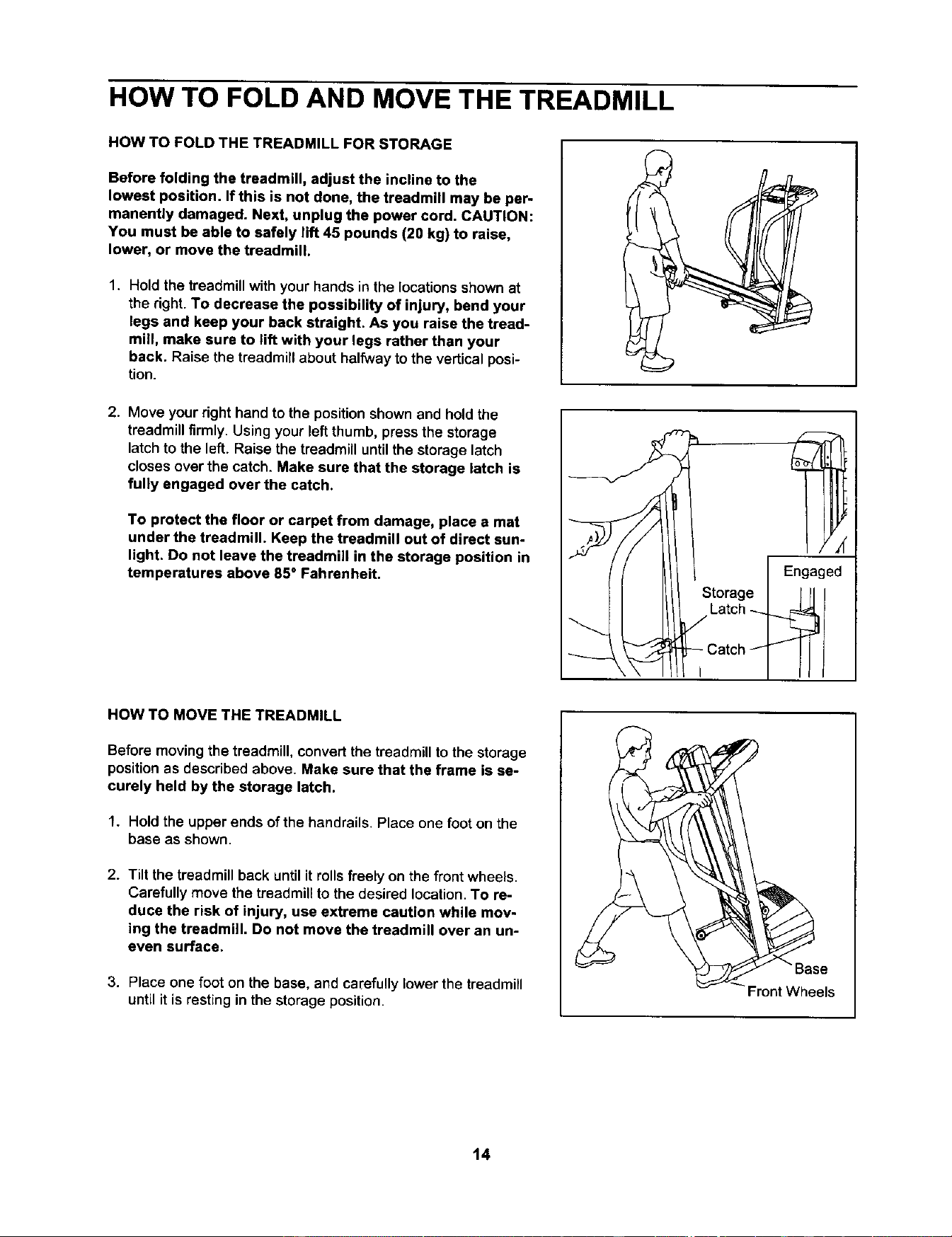
1. Hold the treadmillwith your hands in the locationsshown at
the right. To decrease the possibility of injury, bend your
legs and keep your back straight. As you raise the tread-
mill, make sure to lift with your legs rather than your
back. Raise the treadmillabout halfwayto the vertical posi-
tion.
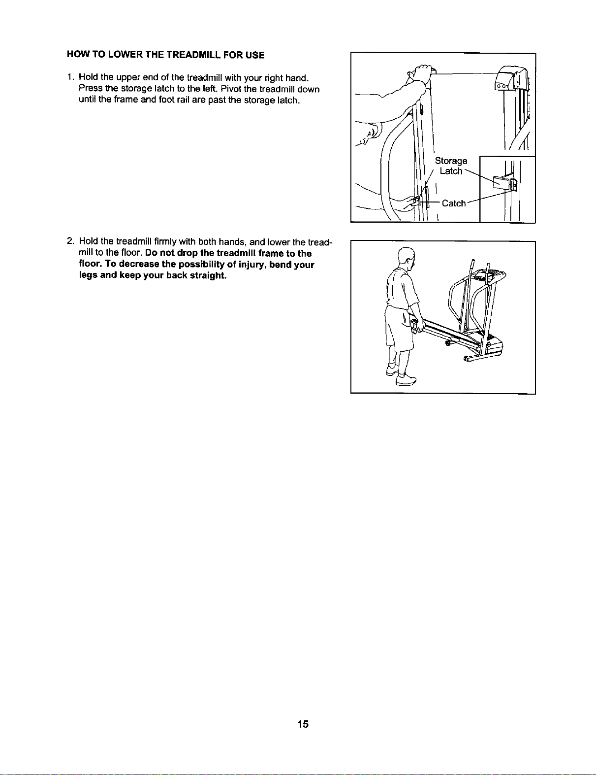
2. Move yourright hand to the position shownand holdthe
treadmill firmly. Using your left thumb, press the storage
latch to the left. Raise the treadmill until the storage latch
closes over the catch. Make sure that the storage latch is
fully engaged over the catch.
To protect the floor or carpet from damage, place a mat
under the treadmill. Keep the treadmill out of direct sun-
light. Do not leave the treadmill in the storage position in
temperatures above 85 ° Fahrenheit.
Engaged
HOW TO MOVE THE TREADMILL
Before moving the treadmill, convert the treadmill to the storage
position as described above. Make sure that the frame is se-
curely held by the storage latch.
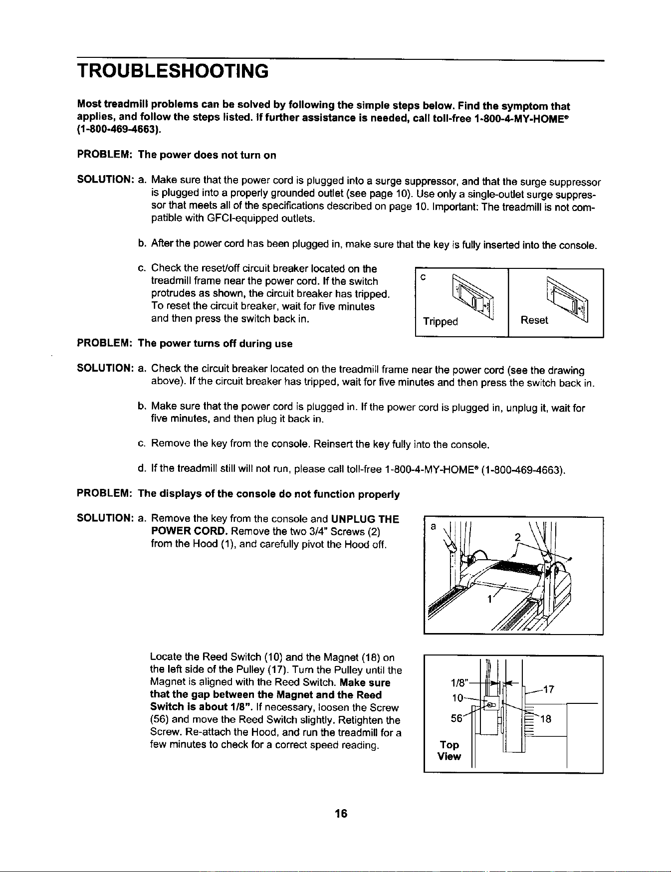
1. Hold the upper ends of the handrails. Place one foot on the
base as shown.
2. Tilt the treadmill back until it rolls freely on the front wheels.
Carefully move the treadmill to the desired location. To re-
duce the risk of injury, use extreme caution while mov-
ing the treadmill. Do not move the treadmill over an un-
even surface.
3. Place one foot on the base, and carefully lower the treadmill
until it is resting in the storage position.
L
_ Front Wheels
14
HOW TO LOWER THE TREADMILL FOR USE
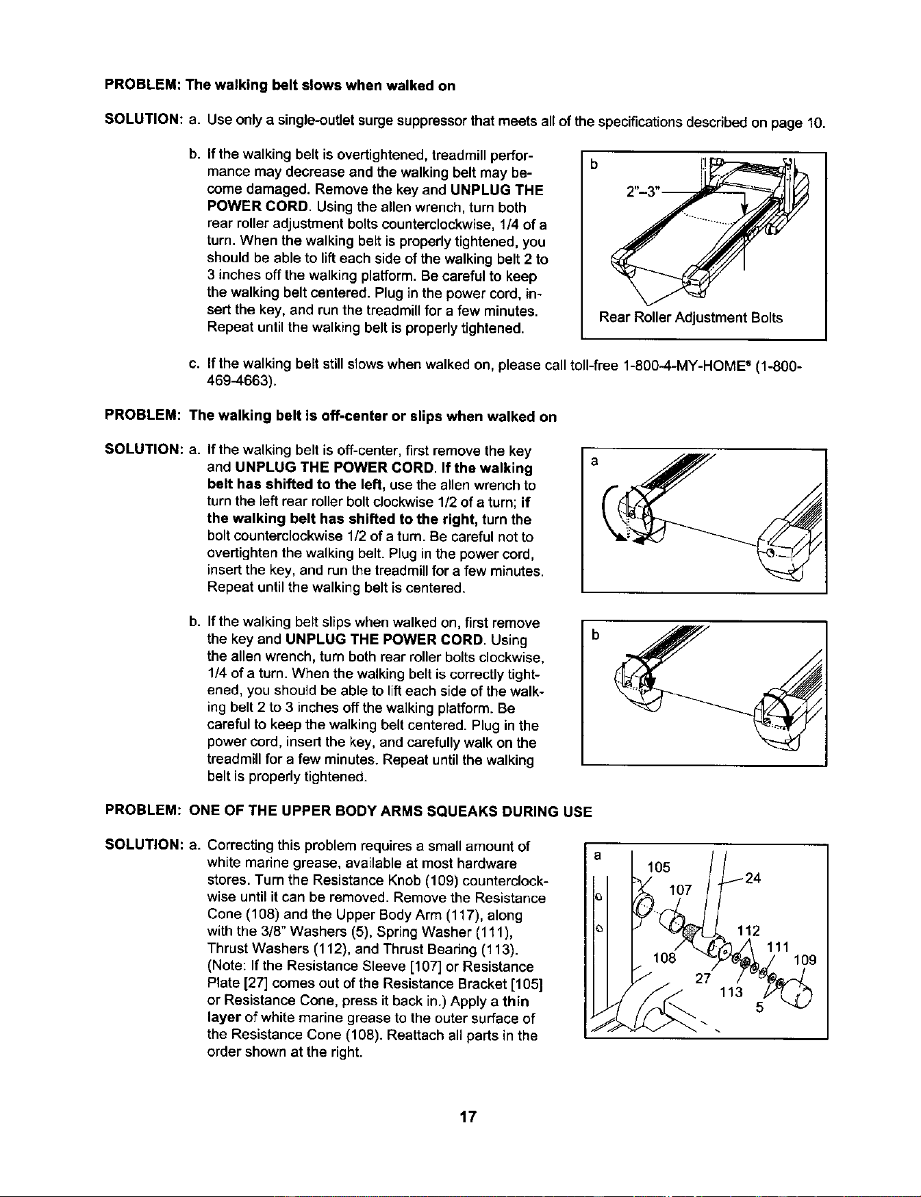
1. Hold the upper end of the treadmill withyour right hand.
Press the storage latch to the left. Pivot the treadmill down
until the frame and foot rail are past the storage latch.
2. Hold the treadmill firmly with both hands, and lower thetread-
mill to the floor. Do not drop the treadmill frame to the
floor. To decrease the possibility of injury, bend your
legs and keep your back straight.
Storage I Ili !
/ 'e'ch l
15
TROUBLESHOOTING
Most treadmill problems can be solved by following the simple steps below. Find the symptom that
applies, and follow the steps listed. If further assistance is needed, call toll-free 1-800-4-MY-HOME ®
(1-800-469-4663).
PROBLEM: The power does not turn on
SOLUTION: a.
Make sure that the power cord isplugged into a surge suppressor,and that the surge suppressor
is pluggedintoa properlygroundedoutlet (see page 10). Use only a single-outletsurge suppres-
sorthat meets all ofthe specificationsdescribed on page 10. Important:The treadmillis notcom-
patible withGFCl-equipped outlets.
b. After the power cord has been plugged in, make sure that the key is fully inserted into the console.
C, Check the reset/offcircuitbreaker locatedon the
treadmillframe near the power cord. If the switch
protrudesas shown, the circuitbreaker has tripped.
To resetthe circuitbreaker, wait for five minutes
and then pressthe switchback in.
PROBLEM: The power turns off during use
_ripped_
Reset_
SOLUTION: a. Check the circuit breaker located on the treadmill frame near the power cord (see the drawing
above). Ifthe circuitbreaker has tripped,wait for five minutesand then pressthe switchback in.
b, Make sure that the power cord is plugged in. If the power cord is plugged in, unplug it, wait for
five minutes, and then plug it back in.
c. Remove the key from the console. Reinsertthe key fully into the console.
d. If the treadmill still will not run, please call toll-free 1-800-4-MY-HOME ® (1-800-469-4663).
PROBLEM: The displays of the console do not function properly
SOLUTION: a. Remove the key fromthe console and UNPLUG THE
POWER CORD. Remove the two 3/4" Screws(2)
from the Hood (1), and carefullypivotthe Hoodoff.
Locate the Reed Switch (10) and the Magnet (18) on
the left side of the Pulley (17). Turn the Pulley until the
Magnet is aligned with the Reed Switch. Make sure
that the gap between the Magnet and the Reed
Switch is about 1/8". If necessary, loosen the Screw
(56) and move the Reed Switch slightly. Retighten the
Screw. Re-attach the Hood, and run the treadmill for a
few minutes to check for a correct speed reading.
56
Top
ViewII
16
PROBLEM: The walking belt slows when walked on
SOLUTION: a. Use onlya single-outlet surge suppressorthat meets all of the specifications describedon page 10.
b,
Ifthe walking belt is overtightened,treadmill perfor-
mance may decrease and the walkingbelt may be-
come damaged. Remove the key and UNPLUG THE
POWER CORD. Usingthe allen wrench, turn both
rear rolleradjustmentboltscounterclockwise,1/4 of a
turn. When the walking belt is properlytightened, you
shouldbe able to lifteach side of the walkingbelt 2 to
3 inchesoff the walkingplatform.Be careful to keep
the walking belt centered. Plugin the power cord, in-
sertthe key, and run the treadmill fora few minutes.
Repeat untilthe walkingbelt isproperlytightened.
b
Rear Roller Adjustment Bolts
c. If the walking belt still slows when walked on, please call toll-free 1-800-4-MY-HOME ®(1-800-
469-4663).
PROBLEM: The walking belt is off-center or slips when walked on
SOLUTION: a.
If the walking belt is off-center, first remove the key
and UNPLUG THE POWER CORD. If the walking
belt has shifted to the left, use the allen wrench to
turn the left rear roller bolt clockwise 1/2 of a turn; if
the walking belt has shifted to the right, turn the
bolt counterclockwise 1/2 of a turn. Be careful not to
overtighten the walking belt. Plug in the power cord,
insert the key, and run the treadmill for a few minutes.
Repeat until the walking belt is centered.
a
1
b,
Ifthe walking belt slips when walkedon, first remove
the key and UNPLUG THE POWER CORD. Using
the allen wrench, turn both rear roller bolts clockwise,
1/4 of a turn. When the walking belt is correctly tight-
ened, you should be able to lift each side of the walk-
ing belt 2 to 3 inches off the walking platform. Be
careful to keep the walking belt centered. Plug in the
power cord, insert the key, and carefully walk on the
treadmill for a few minutes. Repeat until the walking
belt is properly tightened.
PROBLEM: ONE OF THE UPPER BODY ARMS SQUEAKS DURING USE
SOLUTION: a.
Correcting this problem requires a small amount of
white marine grease, available at most hardware
stores. Turn the Resistance Knob (109) counterclock-
wise until it can be removed. Remove the Resistance
Cone (108) and the Upper Body Arm (117), along
with the 318"Washers (5), Spring Washer (111),
Thrust Washers (112), and Thrust Bearing (113).
(Note: If the Resistance Sleeve [107] or Resistance
Plate [27] comes out of the Resistance Bracket [105]
or Resistance Cone, pressit back in.) Apply a thin
layer of white marine grease to the outer surface of
the Resistance Cone (108). Reattach all parts in the
order shown at the right.
105
112
111
5
17
CONDITIONING GUIDELINES
The following guidelines will help you to plan your ex-
ercise program. For more detailed exercise informa-
tion, obtain a reputable book or consult your physician.
EXERCISE INTENSITY
Whether your goal is to burn fat or to strengthen your
cardiovascular system, the key to achieving the
desired results is to exercise with the proper intensity.
The proper intensity level can be found by using your
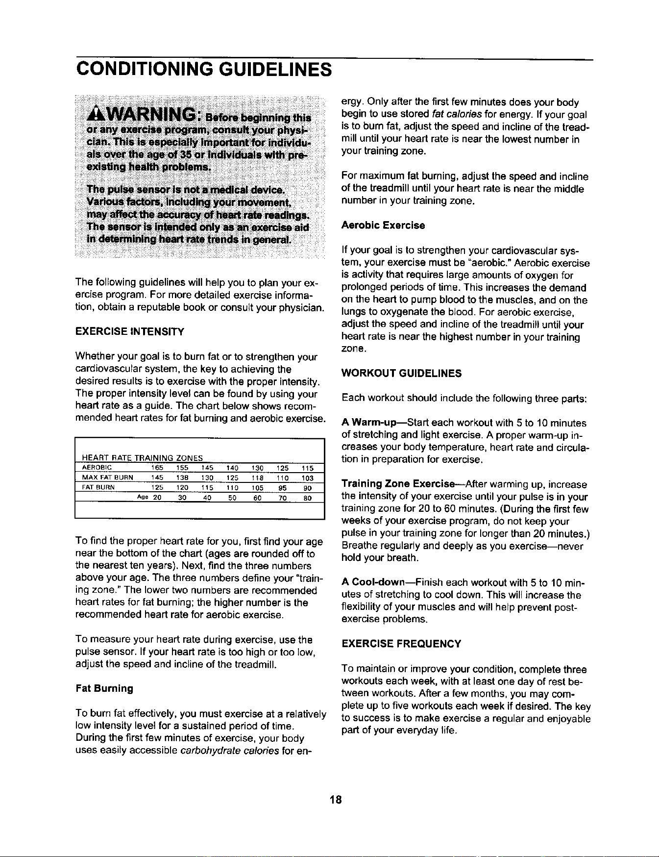
heart rate as a guide. The chart below shows recom-
mended heart rates for fat burning and aerobic exercise.
HEART RATE TRAINING ZONES
AEROBIC 165 155 _4B 140 130 125 115
MAX FAT BURN 145 138 130 125 118 110 103
FAT BURN 125 120 llB 110 105 95 90
Ag e 20 30 40 50 60 70 80
To find the proper heart rate for you, first find your age
near the bottom of the chart (ages are rounded off to
the nearest ten years). Next, find the three numbers
above your age. The three numbers define your "train-
ing zone." The lower two numbers are recommended
heart rates for fat burning; the higher number is the
recommended heart rate for aerobic exercise.
To measure your heart rate during exercise, use the
pulse sensor. If your heart rate is too high or too low,
adjust the speed and incline of the treadmill.
Fat Burning
To burn fat effectively, you must exercise at a relatively
low intensity level for a sustained period of time.
During the first few minutes of exercise, your body
uses easily accessible carbohydrate calories for en-
ergy. Only afterthe first few minutes does your body
begin to usestored fat calories for energy. If your goal
is to burn fat, adjust the speed and incline of the tread-
mill until your heart rate is near the lowest number in
your training zone.
For maximum fat burning, adjust the speed and incline
of the treadmill until your heart rate is near the middle
number in your training zone.
Aerobic Exercise
If your goal is to strengthen your cardiovascular sys-
tem, your exercise must be "aerobic." Aerobic exercise
is activity that requires large amounts of oxygen for
prolonged periods of time. This increases the demand
on the heart to pump blood to the muscles, and on the
lungs to oxygenate the blood. For aerobic exercise,
adjust the speed and incline of the treadmill until your
heart rate is near the highest number in your training
zone.
WORKOUT GUIDELINES
Each workout should include the following three parts:
A Warm-up--Start each workout with 5 to 10 minutes
of stretching and light exercise. A proper warm-up in-
creases your body temperature, heart rate and circula-
tion in preparation for exercise.
Training Zone Exercise---After warming up, increase
the intensityof yourexercise untilyour pulse is in your
trainingzone for 20 to60 minutes. (Duringthe firstfew
weeks of yourexercise program, do not keep your
pulse inyourtrainingzone for longer than20 minutes.)
Breatheregularly and deeply as youexercise--never
hold your breath.
A Cool-down--Finish each workout with 5 to 10 min-
utes ofstretching to cool down.This will increase the
flexibility of your musclesand will help prevent post-
exercise problems.
EXERCISE FREQUENCY
To maintain or improve your condition, complete three
workouts each week, with at least one day of rest be-
tween workouts. After a few months, you may com-
plete up to five workouts each week if desired. The key
to success is to make exercise a regular and enjoyable
part of your everyday life.
18
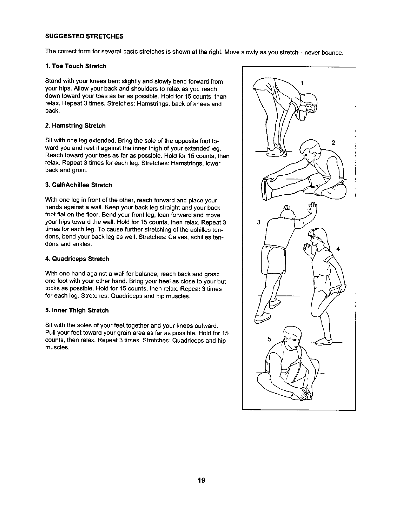
SUGGESTED STRETCHES
The correct form for several basic stretches is shown at the right. Move slowlyas you stretch--never bounce.
1. Toe Touch Stretch
Stand with your knees bent slightlyand slowlybend forwardfrom
yourhips.Allow your back and shouldersto relax as you reach
downtoward your toes as far as possible.Holdfor 15 counts,then
relax. Repeat 3 times. Stretches:Hamstrings,back ofknees and
back.
2. Hamstring Stretch
Sit with one leg extended. Bring the soleof the opposite foot to-
ward you and rest it against the inner thigh of your extended leg.
Reach toward your toes as far as possible. Hold for 15 counts, then
relax. Repeat 3 times for each leg. Stretches: Hamstrings, lower
back and groin.
3. CalflAchilles Stretch
With one leg in front of the other, reach forward and place your
hands against a wall. Keep your back leg straight and your back
foot flat on the floor. Bend your front leg, lean forward and move
your hips toward the wall. Hold for 15 counts, then relax. Repeat 3
times for each leg. To cause further stretching of the achilles ten-
dons, bend your back leg as well. Stretches: Calves, achilles ten-
dons and ankles,
4. Quadriceps Stretch
With one hand against a wall for balance, reach back and grasp
one foot with your other hand. Bring your heel as close to your but-
tocks as possible. Hold for 15 counts, then relax. Repeat 3 times
for each leg. Stretches: Quadriceps and hip muscles.
5. Inner Thigh Stretch
Sit with the solesof your feet together and your knees outward.
Pull your feet toward your groin area as far as possible. Hold for 15
counts, then relax. Repeat 3 times. Stretches: Quadriceps and hip
muscles.
19
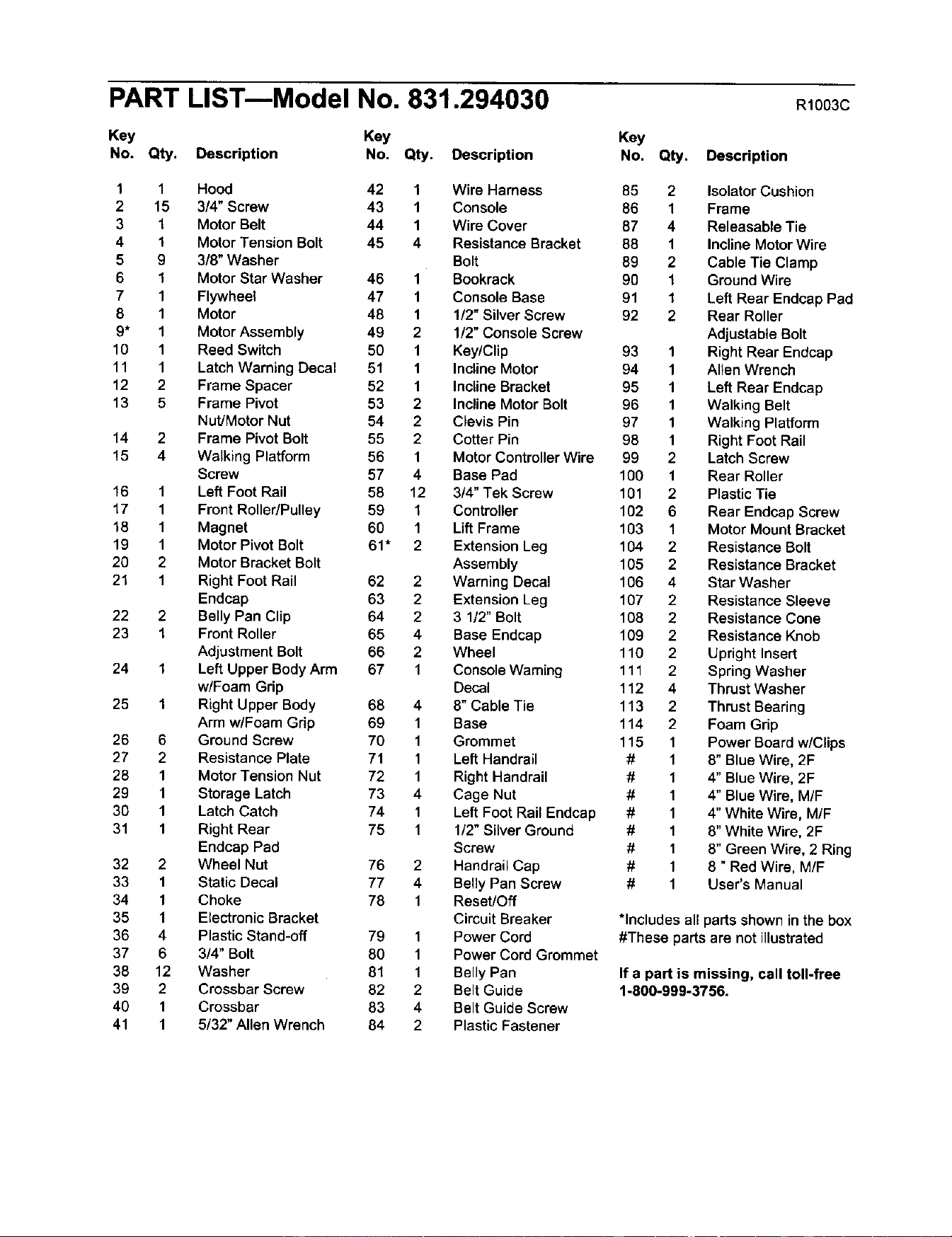
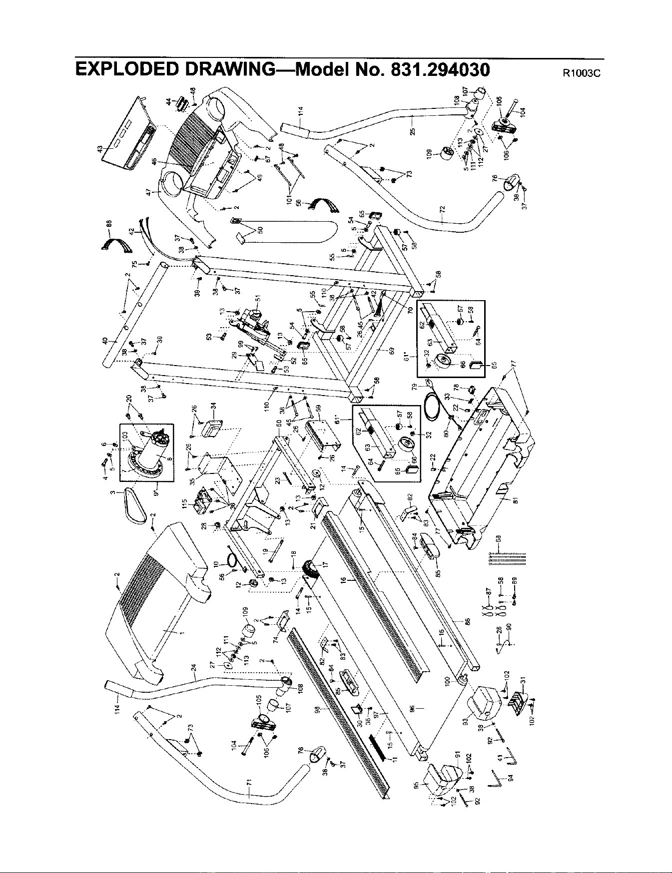
PART LISTmModel No. 831.294030 R10o3c
Key Key Key
No. Qty. Description No. Qty. Description No. Qty. Description
1 1 Hood 42 1 Wire Harness
2 15 3/4" Screw 43 1 Console
3 1 Motor Belt 44 1 Wire Cover
4 1 Motor Tension Bolt 45 4 ResistanceBracket
5 9 3/8" Washer Bolt
6 1 Motor Star Washer 46 1 Bookrack
7 1 Flywheel 47 1 ConsoleBase
8 1 Motor 48 1 1/2" Silver Screw
9* 1 Motor Assembly 49 2 1/2" Console Screw
10 1 Reed Switch 50 1 Key/Clip
11 1 LatchWarning Decal 51 1 Incline Motor
12 2 Frame Spacer 52 1 InclineBracket
13 5 Frame Pivot 53 2 Incline Motor Bolt
Nut/Motor Nut 54 2 Clevis Pin
14 2 Frame Pivot Bolt 55 2 Cotter Pin
15 4 Walking Platform 56 1 Motor ControllerWire
Screw 57 4 Base Pad
16 1 Left Foot Rail 58 12 3/4" Tek Screw
17 1 FrontRoller/Pulley 59 1 Controller
18 1 Magnet 60 1 LiftFrame
19 1 Motor Pivot Bolt 61" 2 ExtensionLeg
20 2 Motor BracketBolt Assembly
21 1 Right Foot Rail 62 2 Warning Decal
Endcap 63 2 ExtensionLeg
22 2 Belly Pan Clip 64 2 3 1/2"Bolt
23 1 Front Roller 65 4 Base Endcap
Adjustment Bolt 66 2 Wheel
24 1 Left Upper Body Arm 67 1 Console Waming
w/Foam Grip Decal
25 1 Right Upper Body 68 4 8" Cable Tie
Arm w/Foam Grip 69 1 Base
26 6 Ground Screw 70 1 Grommet
27 2 Resistance Plate 71 1 Left Handrail
28 1 Motor Tension Nut 72 1 Right Handrail
29 1 Storage Latch 73 4 Cage Nut
30 1 Latch Catch 74 1 Left Foot Rail Endcap
31 1 Right Rear 75 1 1/2" Silver Ground
Endcap Pad Screw
32 2 Wheel Nut 76 2 Handrail Cap
33 1 Static Decal 77 4 Belly Pan Screw
34 1 Choke 78 1 Reset/Off
35 1 Electronic Bracket Circuit Breaker
36 4 Plastic Stand-off 79 1 Power Cord
37 6 3/4" Bolt 80 1 Power Cord Grommet
38 12 Washer 81 1 Belly Pan
39 2 Crossbar Screw 82 2 Belt Guide
40 1 Crossbar 83 4 Belt Guide Screw
41 1 5/32" Allen Wrench 84 2 Plastic Fastener
85 2 IsolatorCushion
86 1 Frame
87 4 Releasable Tie
88 1 InclineMotorWire
89 2 Cable Tie Clamp
90 1 Ground Wire
91 1 Left Rear Endcap Pad
92 2 Rear Roller
AdjustableBolt
93 1 Right Rear Endcap
94 1 Allen Wrench
95 1 Left Rear Endcap
96 1 Walking Belt
97 1 Walking Platform
98 1 RightFoot Rail
99 2 LatchScrew
100 1 Rear Roller
101 2 PlasticTie
102 6 Rear Endcap Screw
103 1 Motor MountBracket
104 2 Resistance Bolt
105 2 Resistance Bracket
106 4 Star Washer
107 2 Resistance Sleeve
108 2 Resistance Cone
109 2 Resistance Knob
110 2 Upright Insert
111 2 Spring Washer
112 4 Thrust Washer
113 2 Thrust Bearing
114 2 Foam Grip
115 1 Power Board w/Clips
# 1 8" Blue Wire, 2F
# 1 4" Blue Wire, 2F
# 1 4" Blue Wire, M/F
# 1 4" White Wire, M/F
# 1 8" White Wire, 2F
# 1 8" Green Wire, 2 Ring
# 1 8 " Red Wire, M/F
# 1 User's Manual
*Includes all parts shown in the box
#These parts are not illustrated
If a part is missing, call toll-free
1-800-999-3756.
104
71
lo6<
107
76
98
38_
37
96
_5 I
102
91
92
41 92
lO
56
16
86
115
23
14
32
_-22
4O
53
13
54
75
4288
47
50
5
54
44
49
67
73 25
0
0
CO

Your Home
For repair - in your home - of all major brand appliances, lawn and garden equipment,
or heating and cooling systems, no matter who made it, no matter who sold it.l
For the replacement parts, accessories, and user's manuals that you need to do-it-yourself.
For Sears professional installation of home appliances
and items like garage door openers and water heaters.
1-800-4-MY-HOME ® Anytime, day or night
(1-800-469-4663) (U.S.A. and Canada)
www.sears.com www.sears.ca
Our Home
For repair of carry-in products like vacuums, lawn equipment,
and electronics, call or go on-line for the location of your nearest
Sears Parts and Repair Center.
1-800-488-1222 Anytime, day or night (U.S.A. only)
www.sears.com
To pumhase a protectionagreement (U.S.A.)
or maintenance agreement (Canada) on a productserviced by Sears:
1-800-827-6655 (u.s._.) 1-800-361-6665 (Canada)
Para pedir serviciode reparaci6n a domicilio,y para ordenar piezas:
1-888-SU-HOGAR sM (1-888-784-6427)
SEARS
® Registered Trademark / _MTrademark / SMService Mark of Sears, Roebuck and Co,
® Mama Registrada / TMMarca de F&bdca / sMMarca de Se_vicio de Sears, Roebuck and Co.
f
FULL 90 DAY WARRANTY
For 90 days from the date of purchase, iffailure occurs due to defect in material or workmanship in this
Sears Treadmill Exerciser,contactthe nearest Sears Service Center throughoutthe United States and
Sears willrepairor replace the Treadmill Exerciser,free of charge.
This warranty does not apply when the Treadmill Exerciser is used commercially or for rental purposes.
This warranty gives you specific legal rights, and you may also have other rights which vary from state to
state.
Sears, Roebuck and Co., Dept. 817WA, Hoffman Estates, IL 60179
Part No. 204148 R1003C Printed in USA © 2003 Sears, Roebuck and Co.