

27 HP- 66" CUT
CELEBRATINGOVER60 YEARSOFINNOVATION
I
1945- 2008
1602 CORPORATE DRIVE, P.O. BOX 67, WARRENSBURG, MISSOURI 64093
PHONE 660-747-8183 FAX 660-747-8650
Manufacturing quality lawn care equipment since 1945
Made In The |
3
USA
OWNER'S MANUAL
STARTING SERIAL # TN108-01601
12530 Rev. 08-221

LIMITED WARRANTY
The manufacturer's warranty to the original consumer purchaser is: This product is free
from defects in materials and workmanship for a period of two (2) years from the date of
purchase by the original consumer purchaser. We will repair or replace, at our discretion,
parts found to be defective due to materials or workmanship. This warranty is subject to
the following limitations and exclusions:
1) Engine Warranty All engines utilized on our products have a separate warranty
extended to them by the individual engine manufacturer. Any
engine service difficulty is the responsibility of the engine
manufacturer and in no way is Swisher Mower Co., Inc. or its
agents responsible for the engine warranty. The Briggs &
Stratton Engine Service Hot-Line is 1-800-233-3723. The
Tecumseh Engine Service Hot-Line is 1-800-558-5402.
2) Commercial Use This product is not intended for commercial use and
carries no commercial warranty,
3) Limitation
4) Exclusions
This warranty applies only to products which have been
properly assembled, adjusted, and operated in accordance
with the instructions contained within this manual. This
warranty does not apply to any product of Swisher Mower
Co., Inc., that has been subject to alteration, misuse,abuse,
improper assembly or installation, shipping damage, or to
normal wear of the product.
Excluded from this warranty are normal wear, normal
adjustments, normal maintenance, and battery*(see
battery section.)
In the event you have a claim under this warranty, you must return the product to an
authorized service dealer. All transportation charges, damage, or loss incurred during
transportation of parts submitted for replacement or repair under this warranty shall be
borne by the purchaser. Should you have any questions concerning this warranty, please
contact us toll-free at 1-800-222-8183. The model number, serial number, date of
purchase, and the name of the authorized Swisher dealer from whom you purchased the
mower will be needed before any warranty claim can be processed.
THIS WARRANTY DOES NOT APPLY TO ANY INCIDENTAL OR CONSEQUENTIAL
DAMAGES AND ANY IMPLIED WARRANTIES ARE LIMITED TO THE SAME TIME
PERIODS STATED HEREIN FOR ALL EXPRESSED WARRANTIES. Some states do not
allow the limitation of consequential damages or limitations on how long an implied
warranty may last, so the above limitations or exclusions may not apply to you. This
warranty gives you specific legal rights and you may have other rights, which vary from
state-to-state. This is a limited warranty as defined by the Magnuson-Moss Act of 1975.
2
iiiii iiiii iiii
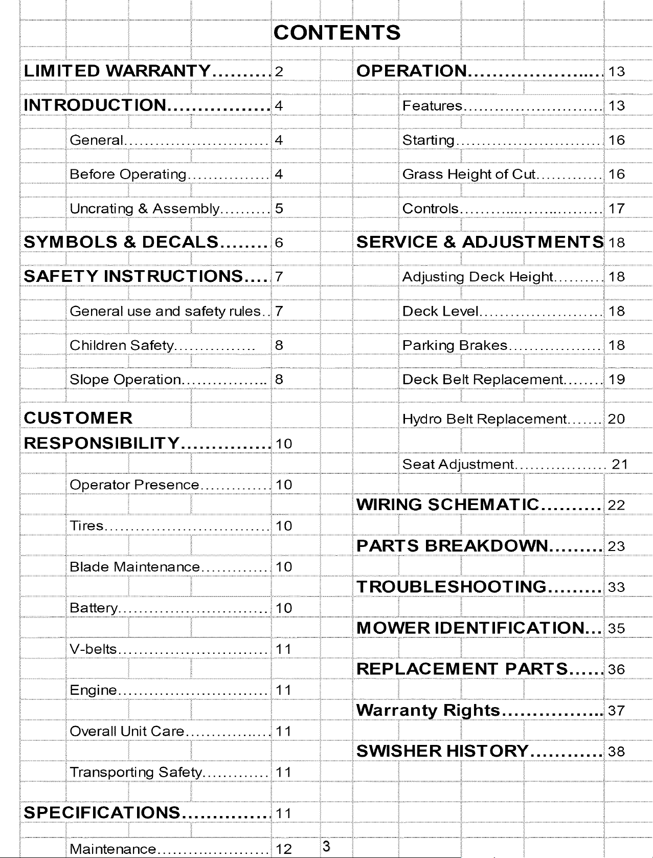
INTRODUCTION ................. ;4
Before Operating ................ 4 Grass Height of Cut ............... 16
¸¸¸!¸¸¸¸¸¸¸8...................................................
Slope Operation ................. 8 19 ..................................................
CUSTOMER Hydro Belt Replacement. 20
RESPONSIBILITY .............. 1 o
Seat Adjustment .................. 21
Operator Presence ............. ., 10
Tires ............................... 10
Blade Maintenance.. ........... .......................................................................................................i...................................................................................................................................................................................................................................................................................................................................................................................................................................................................................................................................................
T RO UB L ES HOOT ING ......... 33
MOWER IDENTIFICATION... 35
.................................................................................................................................................REPLAeEMENTP ...................................................
Engine.. 1 1 ..........................................................................................................................................................................................................
i
Overall Unit Care.. 1 1
.............. ......................................................................................................................................................................................................................................................................................................................................................................................................................................................................................................................................................................................
..........................................................................................................................................................................SWISHER HISTORY ............ 38
; Transporting ...................................................................................................................................................................................................................................................................................................................................................................................................................................................................................................................................................................................................................................
..............................................................................Maintenance.. .................... ......................................................3 ............................................................................................................................................................................................................................................................................................................................................................................................................................................................................................................................................................................
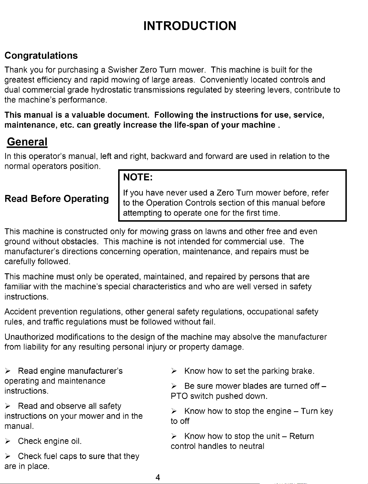
INTRODUCTION
Congratulations
Thank you for purchasing a Swisher Zero Turn mower. This machine is built for the
greatest efficiency and rapid mowing of large areas. Conveniently located controls and
dual commercial grade hydrostatic transmissions regulated by steering levers, contribute to
the machine's performance.
This manual is a valuable document. Following the instructions for use, service,
maintenance, etc. can greatly increase the life-span of your machine.
General
In this operator's manual, left and right, backward and forward are used in relation to the
normal operators position.
NOTE:
Read Before Operating
If you have never used a Zero Turn mower before, refer
to the Operation Controls section of this manual before
attempting to operate one for the first time.
This machine is constructed only for mowing grass on lawns and other free and even
ground without obstacles. This machine is not intended for commercial use. The
manufacturer's directions concerning operation, maintenance, and repairs must be
carefully followed.
This machine must only be operated, maintained, and repaired by persons that are
familiar with the machine's special characteristics and who are well versed in safety
instructions.
Accident prevention regulations, other general safety regulations, occupational safety
rules, and traffic regulations must be followed without fail.
Unauthorized modifications to the design of the machine may absolve the manufacturer
from liability for any resulting personal injury or property damage.
Read engine manufacturer's
operating and maintenance
instructions.
Read and observe all safety
instructions on your mower and in the
manual.
Check engine oil.
Check fuel caps to sure that they
are in place.
Know how to set the parking brake.
Be sure mower blades are turned off-
PTO switch pushed down.
Know how to stop the engine - Turn key
to off
Know how to stop the unit - Return
control handles to neutral
4
INTRODUCTION
Uncrating & Assembly
TOOLS REQUIRED:
,/ 2 - ½" Wrenches or ½" Socket with drive ratchet
,/ Tire pressure gauge
,/ Nail bar or claw hammer
,/ Wire snips
To Remove The Mower From The Crate:
Dispose of top and side panels of the crate.
Remove loose parts and packing material.
Cut any banding or strapping that may be holding the mower to the crate.
Disengage spark plug wire and place where it cannot make a connection.
Raise the mower deck to its highest position.
Install steering levers. Remove the bolts from the control arms on the mower. Align
the holes in the lever with the holes in the control arms and attach with the bolts provided.
Make sure both bolts on both handles are tight.
Disengage the parking brake by pushing the handles to their fully extended position.
Open the transmission valves at the rear of the unit by pulling the release rods and
locking them in place. SEE INSTRUCTION DECAL AT THE REAR OF THE UNIT.
Carefully push the mower off the crate to a safe and level area.
Check engine oil. All engines are filled with oil and tested at the factory. Verify oil
level and add if necessary before starting engine. SEE ENGINE OWNER'S MANUAL
Check the battery. If the battery is put into service after the "month & year" of the
date on the battery, then it may need to be charged with a 12 volt charger for a minimum
of 1 hour, but no more than 2 hours at a rate of 6 to 10 amps.
Attach battery cables to battery. Always attach the positive terminal first.
Close the transmission valves at the rear of the unit. SEE INSTRUCTION DECAL
AT THE REAR OF THE UNIT.
Reconnect spark plug wire.
Check tire pressure on all four wheels. REFER TO UNIT SPECIFICATIONS TABLE
5
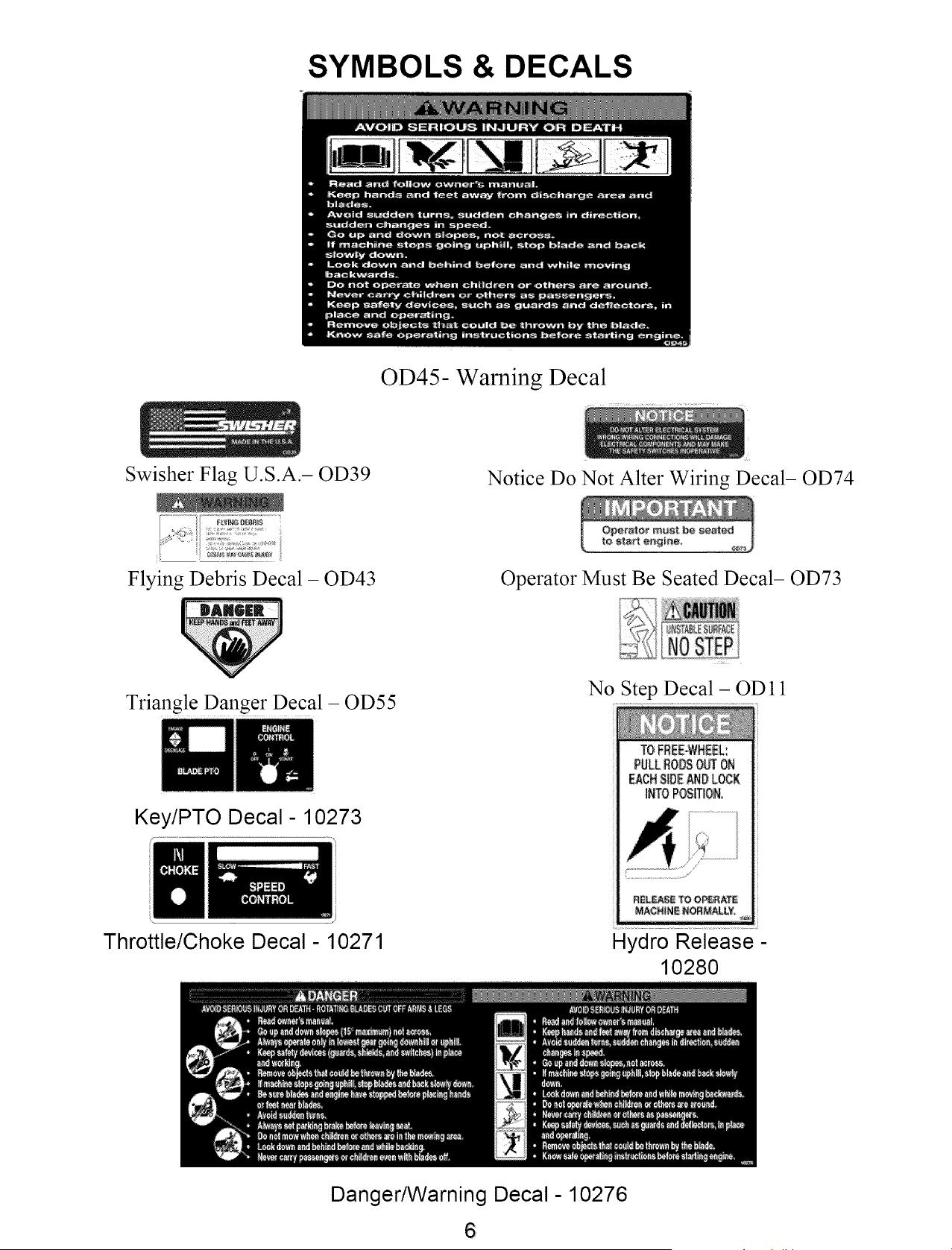
SYMBOLS & DECALS
OD45- Warning Decal
Swisher Flag U.S.A.- OD39
Notice Do Not Alter Wiring Decal- OD74
Flying Debris Decal - OD43
Operator Must Be Seated Decal- OD73
Triangle Danger Decal - OD55
Key/PTO Decal- 10273
Throttle/Choke Decal - 10271
N(
Step Decal - OD 11
TO_RE[oWHEEL:
PgLLRODSON OR
EACHNDE_D LOCK
INTOPOSITION.
R£L_E _ O_RAlrE
MACHIN_NOR_L¥=
Hydro Release-
10280
Danger/Warning Decal- 10276
6
General Use
SAFETY INSTRUCTIONS
These instructions are for your safety. Read them carefully.
This Safety Alert Symbol indicates important messages in this manual. When
you see this symbol, carefully read the message that follows and be alert to the
possibility of personal injury.
Read all instructions in this operator's manual and on the
machine before starting it. Ensure that you understand them and
then abide by them.
_Learn how to use the machine and its controls safely and learn
how to stop quickly. Also learn to recognize the safety decals.
Only allow the machine to be used by adults who are familiar
with its use.
Make sure nobody else is in the area of the machine when you
start the engine, engage the drive, or run the machine.
_Stop the machine if someone enters the work area.
_Clear the area of objects such as stones, toys, steel wire, etc.
that may become caught in the blades and thrown out.
_Do Not Use this machine without the Discharge
Chute in place.
Stop the engine and disconnect the spark plug before cleaning
the discharge deck.
Never take passengers. The machine is only intended for use
by one person.
Always look around before and during reversing maneuvers.
Slow down before turning.
Shut down the mower deck when not mowing.
Be careful when rounding fixed objects, so that the blades do
not hit them.
Only operate the machine in daylight or other well-lit
conditions.
Keep the machine a safe distance from holes or other
irregularities in the ground.
Never use the machine if you are tired, if you have consumed
alcohol, or if you are taking other drugs or medications that can
affect your vision, judgment, or coordination.
Beware of traffic when working near or crossing a road.
Never leave the machine unsupervised with the engine running.
Always shut down the blades, engage the parking brake, stop the
engine, and remove the ignition key before leaving the machine.
Never allow children or other persons not trained in the use of
the machine to use or service it. Local laws may regulate the age
of the user.
Make sure that you have first aid equipment close at hand
when using the machine.
Never use the machine when barefoot. Always wear protective
shoes or boots.
NOTE:
If you have never used a Zero Turn
mower before, refer to the Operation
Controls section of this manual before
attempting to operate one for the first
time.
7
SAFETY INSTRUCTIONS
General Use Continued...
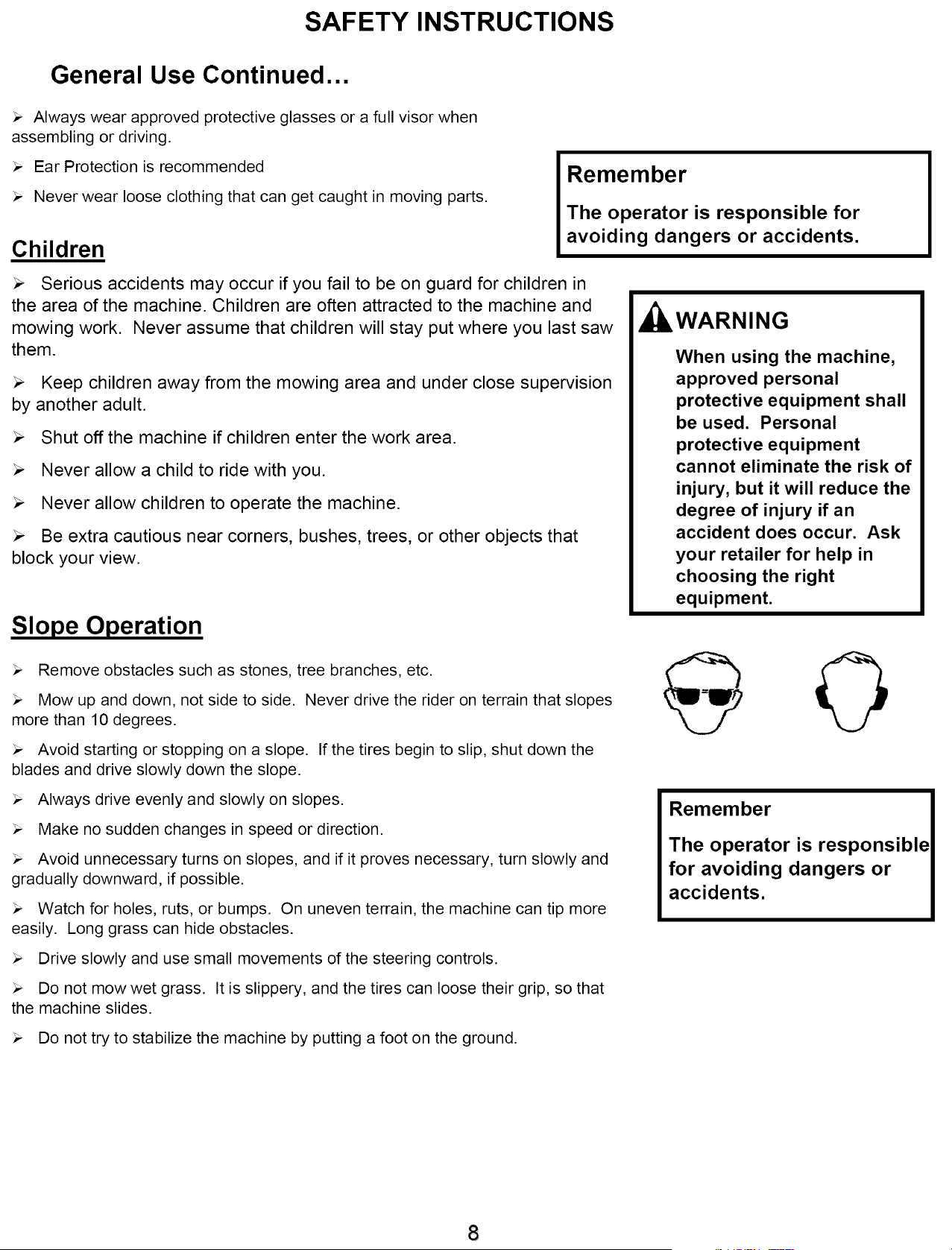
Always wear approved protective glasses or a full visor when
assembling or driving.
Ear Protection is recommended
Never wear loose clothing that can get caught in moving parts.
Children
Remember
The operator is responsible for
avoiding dangers or accidents.
>. Serious accidents may occur if you fail to be on guard for children in
the area of the machine. Children are often attracted to the machine and
mowing work. Never assume that children will stay put where you last saw
them.
>. Keep children away from the mowing area and under close supervision
by another adult.
Shut off the machine if children enter the work area.
Never allow a child to ride with you.
Never allow children to operate the machine.
>. Be extra cautious near corners, bushes, trees, or other objects that
block your view.
Slope Operation
Remove obstacles such as stones, tree branches, etc.
Mow up and down, not side to side. Never drive the rider on terrain that slopes
more than 10 degrees.
Avoid starting or stopping on a slope. If the tires begin to slip, shut down the
blades and drive slowly down the slope.
Always drive evenly and slowly on slopes.
Make no sudden changes in speed or direction.
Avoid unnecessary turns on slopes, and if it proves necessary, turn slowly and
gradually downward, if possible.
Watch for holes, ruts, or bumps. On uneven terrain, the machine can tip more
easily. Long grass can hide obstacles.
Drive slowly and use small movements of the steering controls.
Do not mow wet grass. It is slippery, and the tires can loose their grip, so that
the machine slides.
WARNING
When using the machine,
approved personal
protective equipment shall
be used. Personal
protective equipment
cannot eliminate the risk of
injury, but it will reduce the
degree of injury if an
accident does occur. Ask
your retailer for help in
choosing the right
equipment.
Remember
The operator is responsible
for avoiding dangers or
accidents.
Do not try to stabilize the machine by putting a foot on the ground.
8
MOWING SAFETY
•WARNING - Petrol is highly flammable.
- store fuel in containers specifically designed for this purpose;
- refuel outdoors only and do not smoke while refueling;
- add fuel before starting the engine. Never remove the cap of the fuel tank or add petrol while the engine
is running or when the engine is hot.
- if petrol is spilled, do not attempt to start the engine but move the machine away from the area of spillage and
avoid creating any source of ignition until petrol vapors have dissipated;
- replace all fuel tanks and container caps securely.
• Replace faulty silencers;
• before using, always visually inspect to see that the blades, blade bolts and cutter assembly are not worn
or damaged. Replace worn or damaged blades and bolts in sets to preserve balance;
• on multi-bladed machines, take care as rotating one blade can cause other blades to rotate.
MAINTENANCE AND STORAGE
• Keep all nuts, bolts and screws tight to be sure the equipment is in safe working condition;
• never store the equipment with petrol in the tank inside a building where fumes can reach an open flame or
spark;
• allow the engine to cool before storing in any enclosure;
• to reduce the fire hazard, keep the engine, silencer, battery compartment and petrol storage area free of grass,
leaves, or excessive grease;
• check the grass catcher frequently for wear or deterioration;
• replace worn or damaged parts for safety;
• if the fuel tank has to be drained, this should be done outdoors.
• when machine is to be parked, stored or left unattended, lower the cutting means unless a positive mechanical
lock is used.
TRAINING
All drivers should seek and obtain professional and practical instruction. Such instruction should emphasize:
• the need for care and concentration when working with ride-on machines;
• control of a ride-on machine sliding on a slope will not be regained by the application of the brake. The main
reason for loss of control are:
i) insufficient wheel grip;
ii) being driven too fast;
iii) inadequate braking;
iv) the type of machine is unsuitable for its task;
v) lack of awareness of the effect of ground conditions, especially slopes;
vi) incorrect hitching and load distribution.
OPERATION
• Do not operate the engine in a confined space where dangerous carbon monoxide fumes can collect;
• when using any attachments, never direct discharge of material toward bystanders nor allow anyone
near the machine while in operation;
• never operate the machine with defective guards, or without safety protective devices in place;
• do not change the engine governor settings or over speed the engine. Operating the engine at excessive
speed can increase the hazard of personal injury;
• disengage drive to attachments, stop the engine, and disconnect the spark plug wire(s) or remove the
ignition key:
- before clearing blockages or unclogging chute;
- before checking, clearing or working on the machine;
- after striking a foreign object. Inspect the machine for damage and make repairs before restarting and
operating the equipment;
- if the machine starts to vibrate abnormally (check immediately);
• stop the engine and disengage drive to attachment:
- before refueling;
- before removing the grass catcher;
- before making height adjustment unless adjustment can be made from the operator's position
9
CUSTOMER RESPONSIBILITIES
Operator Presence System
Be sure the operator presence and interlock systems are working properly. If your mower does not function as
described, repair the problem immediately.
The engine should not start unless the parking brake is engaged and the PTO (Blade Engagement
- See OPERATION FEATURES section of this manual) switch is disengaged (pressed down).
When the engine is running, the operator should never leave the seat without first setting the parking
brake and shutting off the engine.
When the engine is running and the PTO switch is engaged, any attempt by the operator to leave
the seat without first disengaging the PTO switch, should shut off the engine.
When the engine is running and the control levers are rotated in, the operator should never attempt
to leave the seat without rotating the control levers out, shutting off the engine and engaging the
parking brake.
_The PTO switch should never engage without the operator on the seat.
Tires
Maintain proper air pressure in all tires ( SEE SPECIFICATIONS section)
Keep tires free of gasoline, oil, or insect control chemicals which can harm rubber.
Avoid stumps, stones, deep ruts, sharp objects and other hazards that may cause tire damage.
Blade Maintenance
CAUTION
Stop engine and remove ignition key for safety. Disconnect spark plug wire. Wear heavy, thick gloves when
holding onto blade. Avoid the sharp edge of the blade.
For best results, mower blades must be kept sharp. Replace bent or damage blades.
Battery
Safely raise front of mower. SEE WARNING
Hold or block blade from turning.
Loosen blade nut and remove blade.
Replace blade, (SEE SPECIFICATIONS).
_i, WARNING
When it is necessary to raise the mower for
any repair or service, use jackstands to
provide adequate support. DO NOT rely on
hydraulic or mechanical jacks
To clean battery and terminals
Remove terminal guard.
_Disconnect the BLACK battery cable first, then the RED battery cable and remove the battery.
Rinse the battery with plain water and dry.
Clean terminals and battery cable ends with wire brush until shiny.
Coat terminals with grease or petroleum jelly
Reinstall battery
WARNING
The battery contains sulfuric acid and
electrolytes which are poisonous and
corrosive.
Reconnect the battery cables
10

CHARGING TIPS
•To avoid a battery explosion, never attempt to charge a frozen
battery.
•Warning: Gel and AGM (Absorbed Glass Mat) batteries require a
voltage-limited charger. Charging a Gel or AGM battery on a typical
shop charger, even one time, may greatly shorten its life.
•Important: Never overcharge batteries. Excessive charging will
shorten battery life.
•Prior to charging, read the manufacturer's instructions for proper
charger hook-up and use.
•Turn off charger prior to hook-up to avoid dangerous sparks.
PROTECT YOUR EYES!
•Warning: If the electrolyte is accessible, verify that plates are
covered before beginning to charge. At the end of charge, add
distilled water as needed to bring levels to the proper height. If
water is added, charge for an additional 30 minutes to mix. If
electrolyte levels are low but battery is not accessible, remove
battery from service.
•The maximum charge rate in amperes should be no more than 1/3
of the battery's reserve capacity minute rating. If the terminal
voltage exceeds 16.0 volts while charging, reduce the charge rate.
•Continue charging and reduce the rate as needed until a 2 hour
period results in no increase in voltage or decrease in current.
•If violent gassing or spewing of electrolyte occurs, or the battery
case feels hot to the touch, temporarily reduce or halt charging.
VOLTAGE
STANDARD
BA-I-I'ERY
6V 12V
STATE
OF
CHARGE
APPROX. BAqq-ERY CHARGING TIME *
TO FULL CHARGE AT 80°F/27°C
MAXIMUM RATE AT
50 AMPS 30 AMPS 20 AMPS 10 AMPS
6.3 12.6 100% FULL CHARGE
6.2 12.4 75% 20 MIN. 35 MIN. 48 MIN. 90 MIN.
6.1 12.2 50% 45 MIN. 75 MIN. 95 MIN. 180 MIN.
6 12 25% 65 MIN. 115 MIN. 145 MIN. 280 MIN.
5.9 11.8 0% 85 MIN, 150 MIN. 195 MIN. 370 MIN.
* Test wet batteries every 4-6 months and recharge if necessary.
Always test and charge if necessary before installation.
CUSTOMER RESPONSIBILITIES/SPECIFICATIONS
V-Belts
Check V-belts for deterioration and wear after 100 hours of operation and replace if necessary.
Replace belts if they begin to slip from wear. SEE SPECIFICATION for belt part numbers and
SERVICE section of this manual for instructions on how to replace the belt.
En,qine
REFER TO YOUR ENGINE OWNERS MANUAL
Overall Unit Care
Reduce the risk of fire by removing grass, leaves, and other debris that may have accumulated on the
machine. Allow the machine time to cool before cleaning or putting it in storage.
_Wash mower periodically. Clean above and below deck.
_Keep all electrical connections clean and tight.
Drivinq and Transport on Public Roads
_Check applicable road traffic regulations before driving and transporting on public roads.
If the machine is transported, you should always use approved fastening equipment and ensure that the
machine is well anchored.
_The cutting deck should also be lowered to the lowest position and the parking brake engaged.
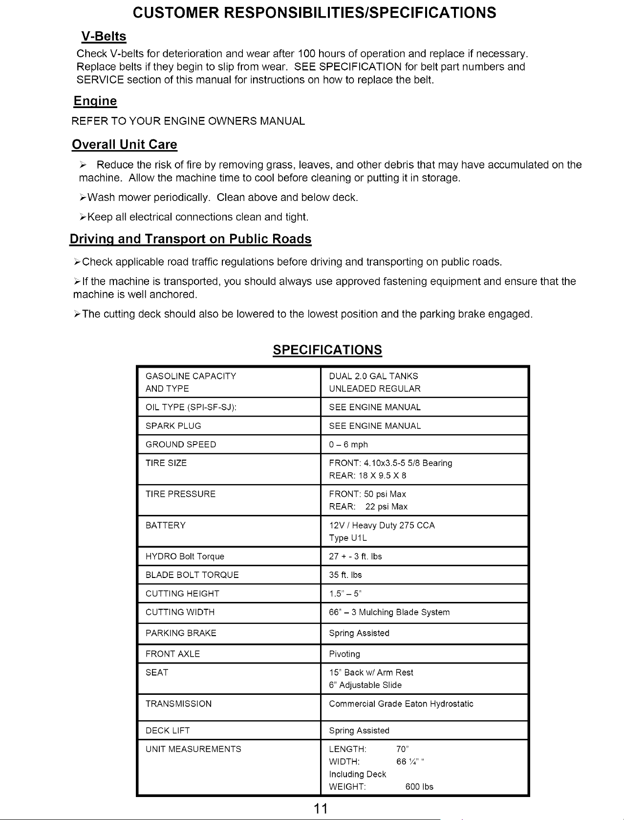
GASOLINE CAPACITY
AND TYPE
OIL TYPE (SPI-SF-SJ):
SPARK PLUG
GROUND SPEED
TIRE SIZE
TIRE PRESSURE
BATTERY
HYDRO Bolt Torque
BLADE BOLT TORQUE
CUTTING HEIGHT
CUTTING WIDTH
PARKING BRAKE
FRONT AXLE
SEAT
TRANSMISSION
DECK LIFT
UNIT MEASUREMENTS
SPECIFICATIONS
DUAL 2.0 GAL TANKS
UNLEADED REGULAR
SEE ENGINE MANUAL
SEE ENGINE MANUAL
0 - 6 mph
FRONT: 4.10x3.5-5 5!8 Bearing
REAR: 18 X 9.5 X 8
FRONT: 50 psi Max
REAR: 22 psi Max
12V ! Heavy Duty 275 CCA
Type U 1L
27 + - 3 ft. Ibs
35 ft. Ibs
1.5"-5"
66" - 3 Mulching Blade System
Spring Assisted
Pivoting
15" Back w! Arm Rest
6" Adjustable Slide
Commercial Grade Eaton Hydrostatic
Spring Assisted
LENGTH: 70"
WIDTH: 66 'A ....
Including Deck
WEIGHT: 600 Ibs
11
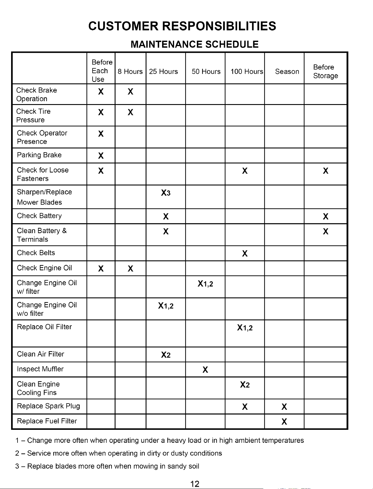
CUSTOMER RESPONSIBILITIES
MAINTENANCE SCHEDULE
Before
Before
Each 8 Hours 25 Hours 50 Hours 100 Hours Season
Use Storage
Check Brake X X
Operation
Check Tire X X
Pressure
Check Operator X
Presence
Parking Brake X
Check for Loose X X X
Fasteners
Sharpen/Replace X3
Mower Blades
Check Battery X X
Clean Battery & X X
Terminals
Check Belts X
Check Engine Oil X X
Change Engine Oil Xl,2
w/filter
Change Engine Oil Xl,2
w/o filter
Replace Oil Filter Xl,2
Clean Air Filter X2
Inspect Muffler X
Clean Engine X2
Cooling Fins
Replace Spark Plug X X
Replace Fuel Filter X
1 - Change more often when operating under a heavy load or in high ambient temperatures
2 - Service more often when operating in dirty or dusty conditions
3 - Replace blades more often when mowing in sandy soil
12

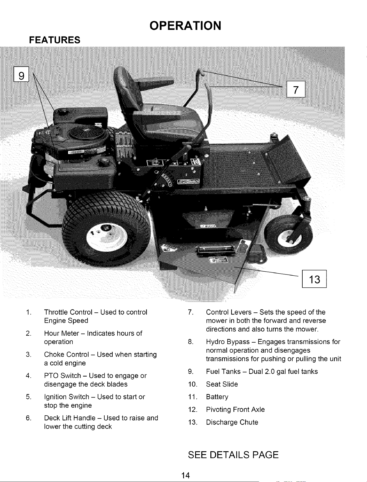
FEATURES
OPERATION
.
.
.
.
.
.
Throttle Control- Used to control
Engine Speed
Hour Meter- Indicates hours of
operation
Choke Control- Used when starting
a cold engine
PTO Switch - Used to engage or
disengage the deck blades
Ignition Switch - Used to start or
stop the engine
Deck Lift Handle - Used to raise and
lower the cutting deck
.
.
.
10.
11.
12.
13.
Control Levers - Sets the speed of the
mower in both the forward and reverse
directions and also turns the mower.
Hydro Bypass - Engages transmissions for
normal operation and disengages
transmissions for pushing or pulling the unit
Fuel Tanks - Dual 2.0 gal fuel tanks
Seat Slide
Battery
Pivoting Front Axle
Discharge Chute
SEE DETAILS PAGE
13
FEATURES
OPERATION
.
.
.
.
.
.
Throttle Control- Used to control
Engine Speed
Hour Meter- Indicates hours of
operation
Choke Control- Used when starting
a cold engine
PTO Switch - Used to engage or
disengage the deck blades
Ignition Switch - Used to start or
stop the engine
Deck Lift Handle - Used to raise and
lower the cutting deck
.
.
.
10.
11.
12.
13.
Control Levers - Sets the speed of the
mower in both the forward and reverse
directions and also turns the mower.
Hydro Bypass - Engages transmissions for
normal operation and disengages
transmissions for pushing or pulling the unit
Fuel Tanks - Dual 2.0 gal fuel tanks
Seat Slide
Battery
Pivoting Front Axle
Discharge Chute
SEE DETAILS PAGE
li4
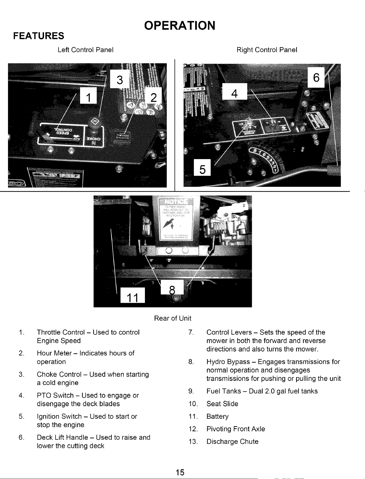
FEATURES
Left Control Panel
OPERATION
Right Control Panel
.
.
.
.
.
.
Throttle Control- Used to control
Engine Speed
Hour Meter- Indicates hours of
operation
Choke Control- Used when starting
a cold engine
PTO Switch - Used to engage or
disengage the deck blades
Ignition Switch - Used to start or
stop the engine
Deck Lift Handle - Used to raise and
lower the cutting deck
Rear of Unit
7.
.
.
10.
11.
12.
13.
Control Levers - Sets the speed of the
mower in both the forward and reverse
directions and also turns the mower.
Hydro Bypass - Engages transmissions for
normal operation and disengages
transmissions for pushing or pulling the unit
Fuel Tanks - Dual 2.0 gal fuel tanks
Seat Slide
Battery
Pivoting Front Axle
Discharge Chute
15
OPERATION
Starting
Operator must be sitting in the seat. Control handles must be in the neutral
(outward) position. PTO must be in the disengage position (pushed down).
Set choke (if needed), turn key and release as soon as engine starts. Adjust
throttle to half and shut choke off.
Be sure all people are clear of the area. Set engine RPM to maximum and then
engage the blades.
Grass Height & Cutting Suggestions
Do not attempt to cut wet grass
NOTE:
If you have never used a Zero
Turn mower before, refer to the
Operation Controls section of
this manual before attempting
to operate one for the first time.
The average lawn should be cut to 2 ½" during the cool season and to over 3"
during the hot months. For healthier and better looking lawns, mow often and after
moderate growth.
As a rule, never cut more than 1/3 of the total grass blade length. Correct
mowing height can reduce weeds and lawn disease.
For best performance, grass over 6 inches in height should be mowed twice.
The first cut should be set relatively high and the second set to the desired height.
16
Controls
OPERATION
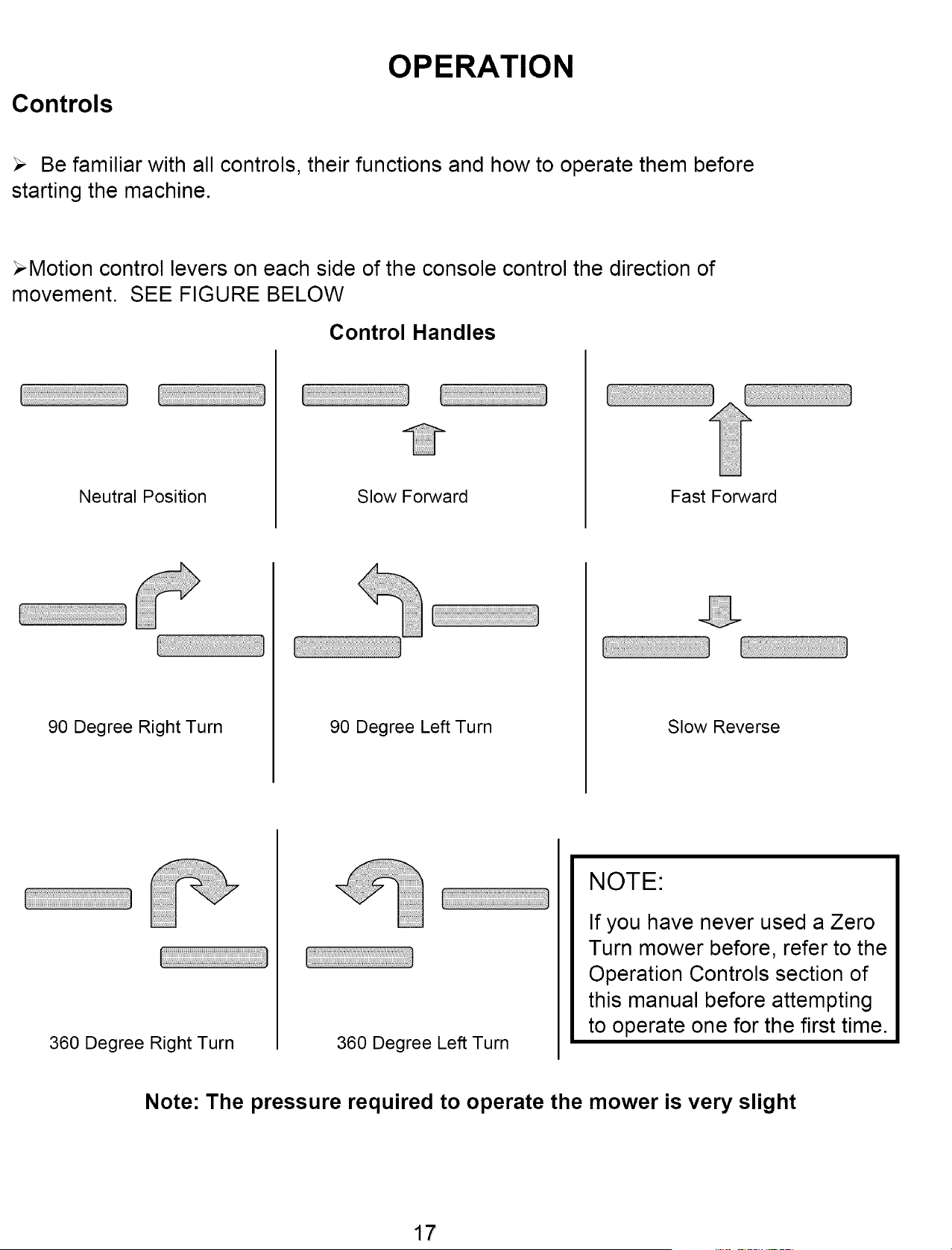
Be familiar with all controls, their functions and how to operate them before
starting the machine.
_Motion control levers on each side of the console control the direction of
movement. SEE FIGURE BELOW
Control Handles
Neutral Position Slow Forward Fast Forward
90 Degree Right Turn 90 Degree Left Turn
Slow Reverse
360 Degree Right Turn 360 Degree Left Turn
NOTE:
If you have never used a Zero
Turn mower before, refer to the
Operation Controls section of
this manual before attempting
to operate one for the first time.
Note: The pressure required to operate the mower is very slight
17
SERVICE & ADJUSTMENTS
Adiustinq The Cuttinq Heiqht
Push out on the Deck Lift Handle and raise or lower the deck to the desired position.
Position 1 is the lowest setting and Position 8 is the highest position
The cutting range is from approximately 1 ½" to approximately 5"
Deck Levelinq
TOOLS REQUIRED:
,/ 2 - ½" Wrenches or ½" Socket with drive ratchet
Lower the cutting deck down to the lowest position (position 1)
Loosen the nuts on the top side of the deck hanger brackets (3 places) where the lift chains attach to.
With all three loose on top of the brackets the deck should now set on the ground resting on the roller
wheels.
Tighten the nuts on the top of the lift brackets making sure that all three lift chains are pulled tight.
Lift deck using the deck lift handle to the desired position
Parkinq Brakes
,/The Swisher ZT2766 is equipped with An Automatic Parking Brake system on each control handle.
,/When the control handles are in the out most position the parking brakes are on.
,/Adjustment for the system is located on the ends of the brake cable at the hydro pan & frame.
,/Raise the rear wheels off the ground
,/Disengage the hydro to be adjusted with the hydro release handle at the rear of the unit.
,/Adjust so that the brake is not on when the handles are in the operator position. The wheel should
turn freely.
,/The wheel should not turn when the handle is moved to the engaged or outward position.
,/To tighten the brake, turn the adjustment nuts towards the end of the cable
,/Recheck adjustment with control handle
,/Lower unit back to the ground
,/Reengage the hydro at the rear of the unit
,_ WARNING
When it is necessary to raise the mower for any
repair or service, use jackstands to provide
adequate support. DO NOT rely on hydraulic or
mechanical jacks
18
SERVICE & ADJUSTMENTS
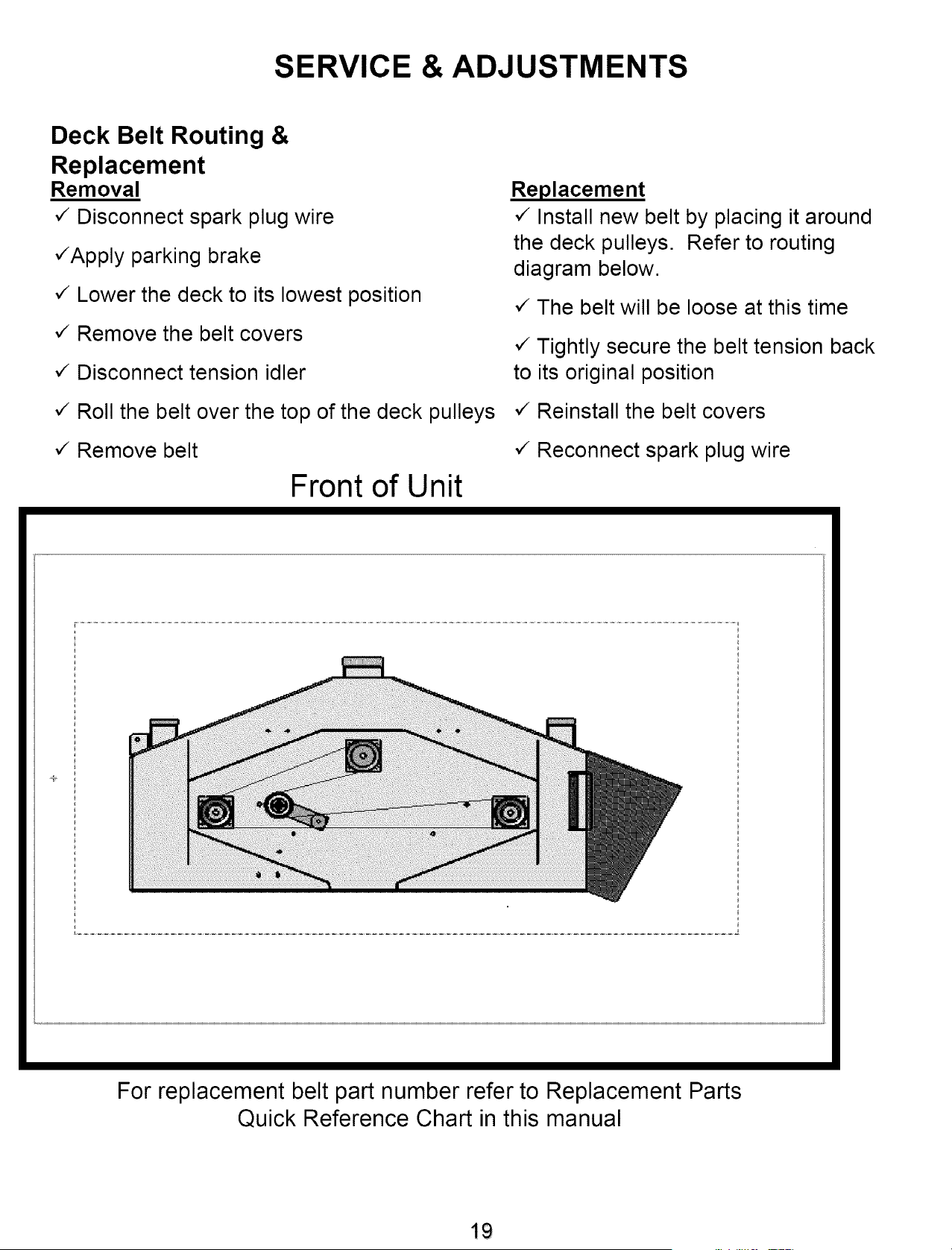
Deck Belt Routing &
Replacement
Removal
,/Disconnect spark plug wire
,/Apply parking brake
,/Lower the deck to its lowest position
,/Remove the belt covers
,/Disconnect tension idler
,/Roll the belt over the top of the deck pulleys
,/Remove belt
Front of Unit
Replacement
,/Install new belt by placing it around
the deck pulleys. Refer to routing
diagram below.
,/The belt will be loose at this time
,/Tightly secure the belt tension back
to its original position
,/Reinstall the belt covers
,/Reconnect spark plug wire
For replacement belt part number refer to Replacement Parts
Quick Reference Chart in this manual
19
SERVICE & ADJUSTMENTS
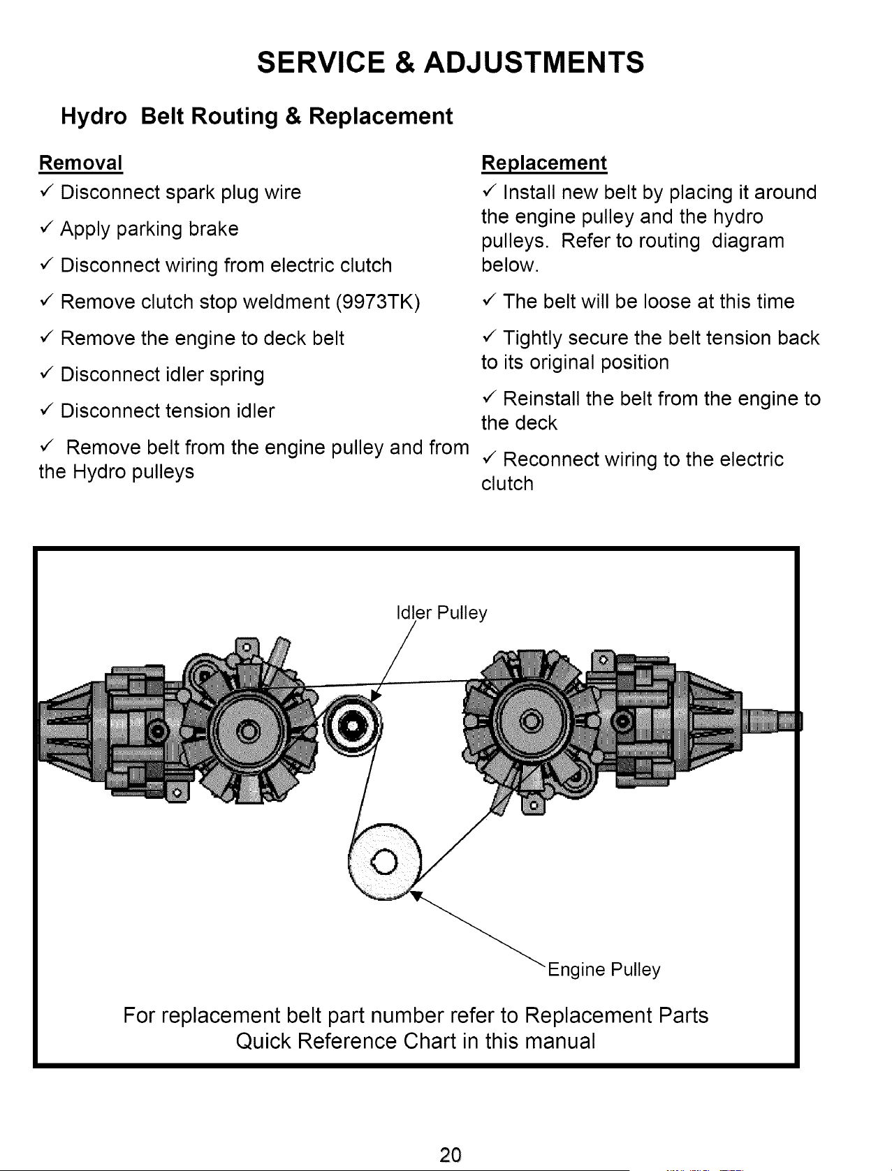
Hydro Belt Routing & Replacement
Removal
,/Disconnect spark plug wire
,/Apply parking brake
,/Disconnect wiring from electric clutch
,/Remove clutch stop weldment (9973TK)
,/Remove the engine to deck belt
,/Disconnect idler spring
,/Disconnect tension idler
,/ Remove belt from the engine pulley and from
the Hydro pulleys
Replacement
,/Install new belt by placing it around
the engine pulley and the hydro
pulleys. Refer to routing diagram
below.
,/The belt will be loose at this time
,/Tightly secure the belt tension back
to its original position
,/Reinstall the belt from the engine to
the deck
,/Reconnect wiring to the electric
clutch
Idler Pulley
Engine Pulley
For replacement belt part number refer to Replacement Parts
Quick Reference Chart in this manual
2O
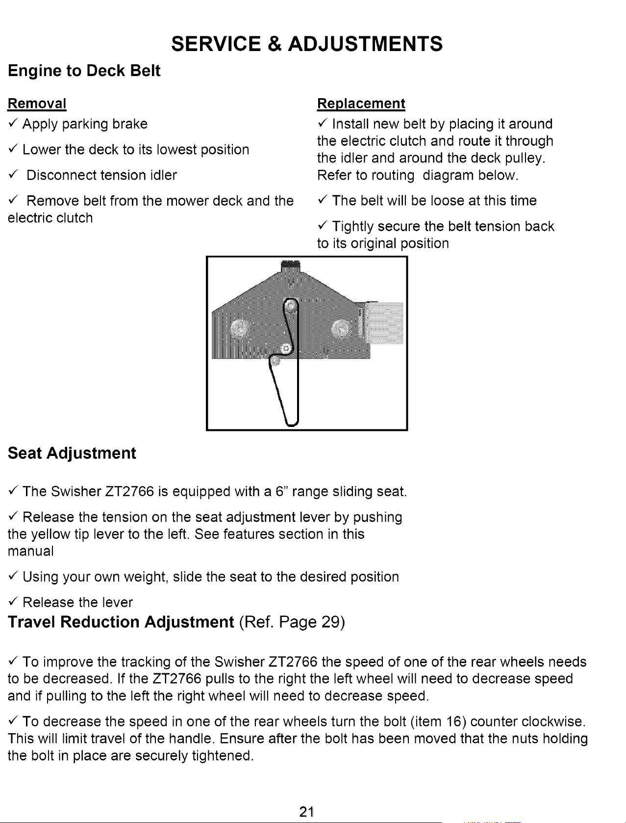
Engine to Deck Belt
SERVICE & ADJUSTMENTS
Removal
,/Apply parking brake
,/Lower the deck to its lowest position
,/ Disconnect tension idler
,/ Remove belt from the mower deck and the
electric clutch
Replacement
,/Install new belt by placing it around
the electric clutch and route it through
the idler and around the deck pulley.
Refer to routing diagram below.
,/The belt will be loose at this time
,/Tightly secure the belt tension back
to its original position
Seat Adjustment
,/The Swisher ZT2766 is equipped with a 6" range sliding seat.
,/Release the tension on the seat adjustment lever by pushing
the yellow tip lever to the left. See features section in this
manual
,/Using your own weight, slide the seat to the desired position
,/Release the lever
Travel Reduction Adjustment (Ref. Page 29)
,/To improve the tracking of the Swisher ZT2766 the speed of one of the rear wheels needs
to be decreased. If the ZT2766 pulls to the right the left wheel will need to decrease speed
and if pulling to the left the right wheel will need to decrease speed.
,/To decrease the speed in one of the rear wheels turn the bolt (item 16) counter clockwise.
This will limit travel of the handle. Ensure after the bolt has been moved that the nuts holding
the bolt in place are securely tightened.
21
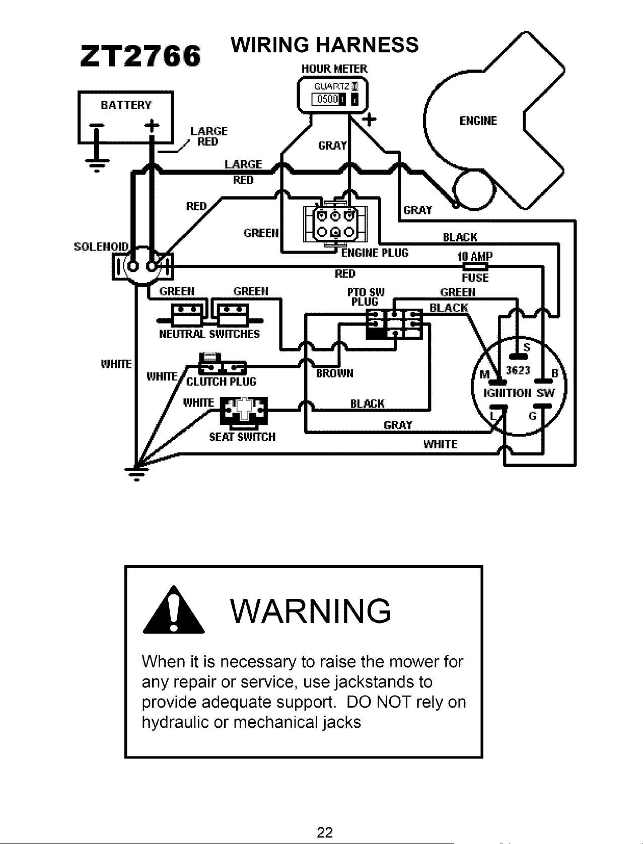
WIRING HARNESS
HOUR METER
WHITE
+
LARGE
RED
_RGE
RED
RED
GREEfl
GREE|J GREEH
NEUTRAL SWITCHES
PLUG
p.IHITE
SEATSWITCH
GRAY
EI'JGIREPLUG
RED
FrO SW
LIG
BLACK
t0 AMP
FUSE
GREEN
BLACK
MITE
E
IGHITIO|| SW
!
.iP
WARNING
When it is necessary to raise the mower for
any repair or service, use jackstands to
provide adequate support. DO NOT rely on
hydraulic or mechanical jacks
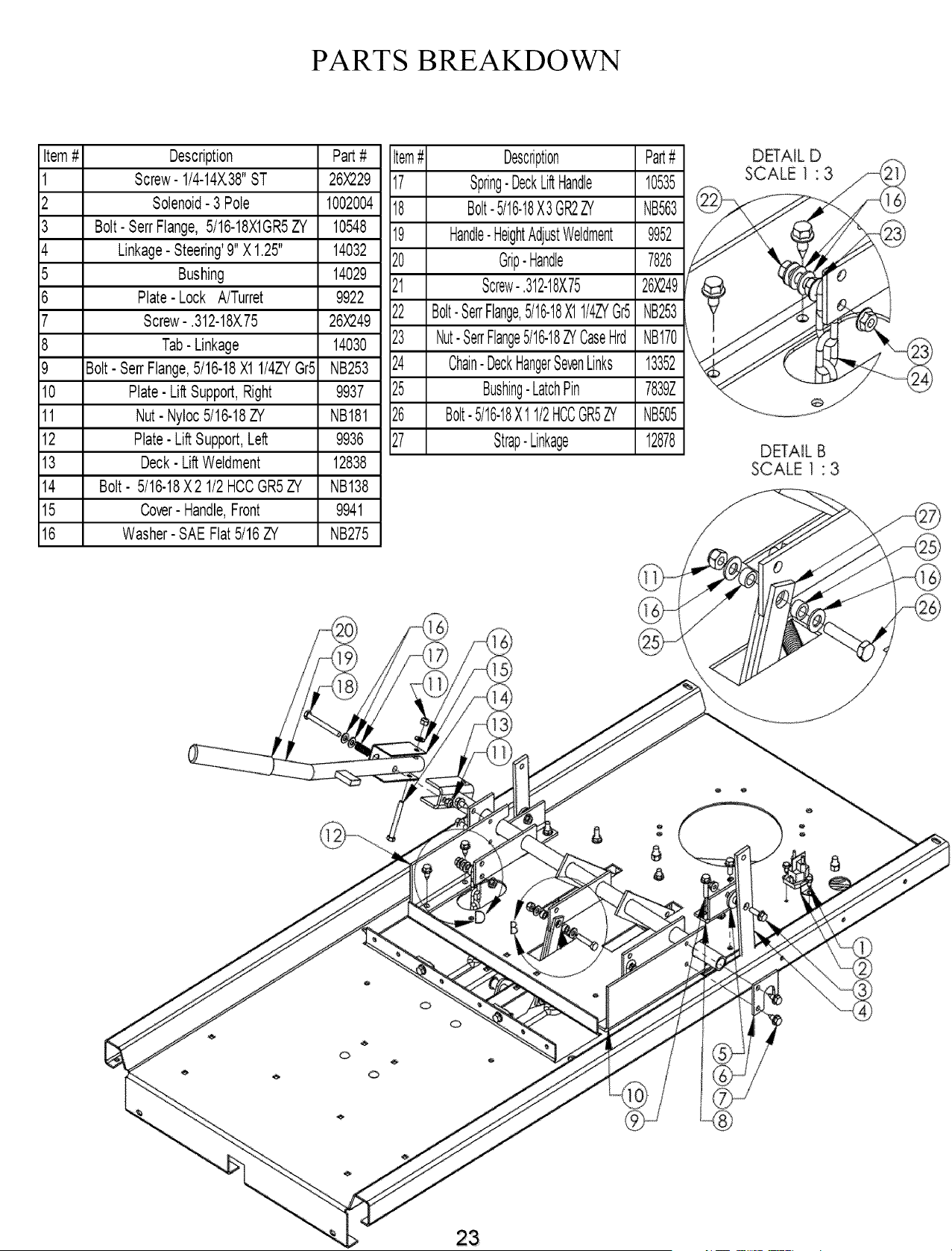
PARTS BREAKDOWN
Item# Description Part#
1 Screw-1/4-14X.38"ST 26X229
2 Solenoid-3 Pole 1002004
3 Bolt- Sen.Flange,5t16-18X1GR5ZY 10548
4 Linkage-Steering'9"X1.25" 14032
5 Bushing 14029
6 Plate- Lock A/Turret 9922
7 Screw-.312-18X.75 26X249
8 Tab- Linkage 14030
9 Bolt- Sen"Flange,5/16-18X1 1/4ZYGr5 NB253
10 Plate-LiftSupport,Right 9937
11 Nut- Nyloc5/16-18ZY NB181
12 Plate-LiftSupport,Left 9936
13 Deck- LiftWeldment 12838
14 Bolt- 5/16-18X2 1/2HCCGR5ZY NB138
15 Cover-Handle,Front 9941
16 Washer-SAEFlat5/16ZY NB275
Item# Description Part#
17 Spring-DeckLiftHandle 10535
18 Bolt-5/16-18X3GR2ZY NB563
19 Handle-HeightAdjustWeldment 9952
20 Grip-Handle 7826
21 Screw-.312-18X75 26X249
22 aott-SerrFlange,5/16-18X1l/4ZVer5NB253
23 Nut-SerrFlange5/16-18ZYCaseHrd NB170
24 Chain-DeckHangerSevenLinks 13352
25 Bushing-LatchPin 7839Z
26 aolt-5/16-18X11/2HCCGR5ZYNB505
27 Strap-Linkage 12878
DETAIL D
SCALE f • 3
DETAIL B
SCALE 1 " 3
o
o
o
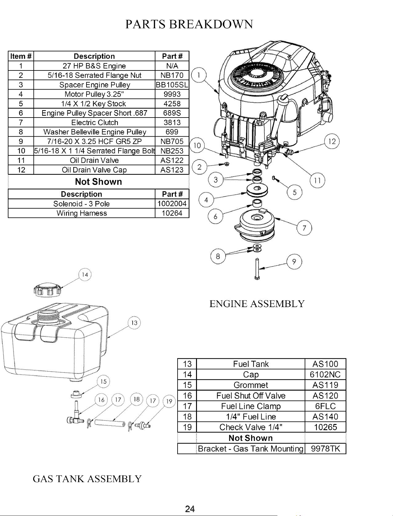
PARTS BREAKDOWN
Item # Description Part #
1 27 HP B&S Engine N/A
2 5/16-18 Serrated Flange Nut NB170
3 Spacer Engine Pulley BB105SL
4 Motor Pulley 3.25" 9993
5 1/4 X 1/2 Key Stock 4258
6 Engine Pulley Spacer Short .687 689S
7 Electric Clutch 3813
8 Washer Belleville Engine Pulley 699
9 7/16-20 X 3.25 HCF GR5 ZP NB705
10 5/16-18 X 1 1/4 Serrated Flange Boll NB253
11 Oil Drain Valve AS122
12 Oil Drain Valve Cap AS123
Not Shown
Description Part #
Solenoid - 3 Pole 1002004
Wiring Harness 10264
ENGINE AS SEMBLY
13 Fuel Tank AS 100
14 Cap 6102NC
15 Grommet AS 119
16 Fuel Shut Off Valve AS120
17 Fuel Line Clamp 6FLC
18 1/4" Fuel Line AS140
19 Check Valve 1/4" 10265
Not Shown
Bracket- Gas Tank Mounting 9978TK
GAS TANK ASSEMBLY
214
Item
1
2
3
4
5
6
7
8
9
10
11
12
14
15
16
17
18
19
20
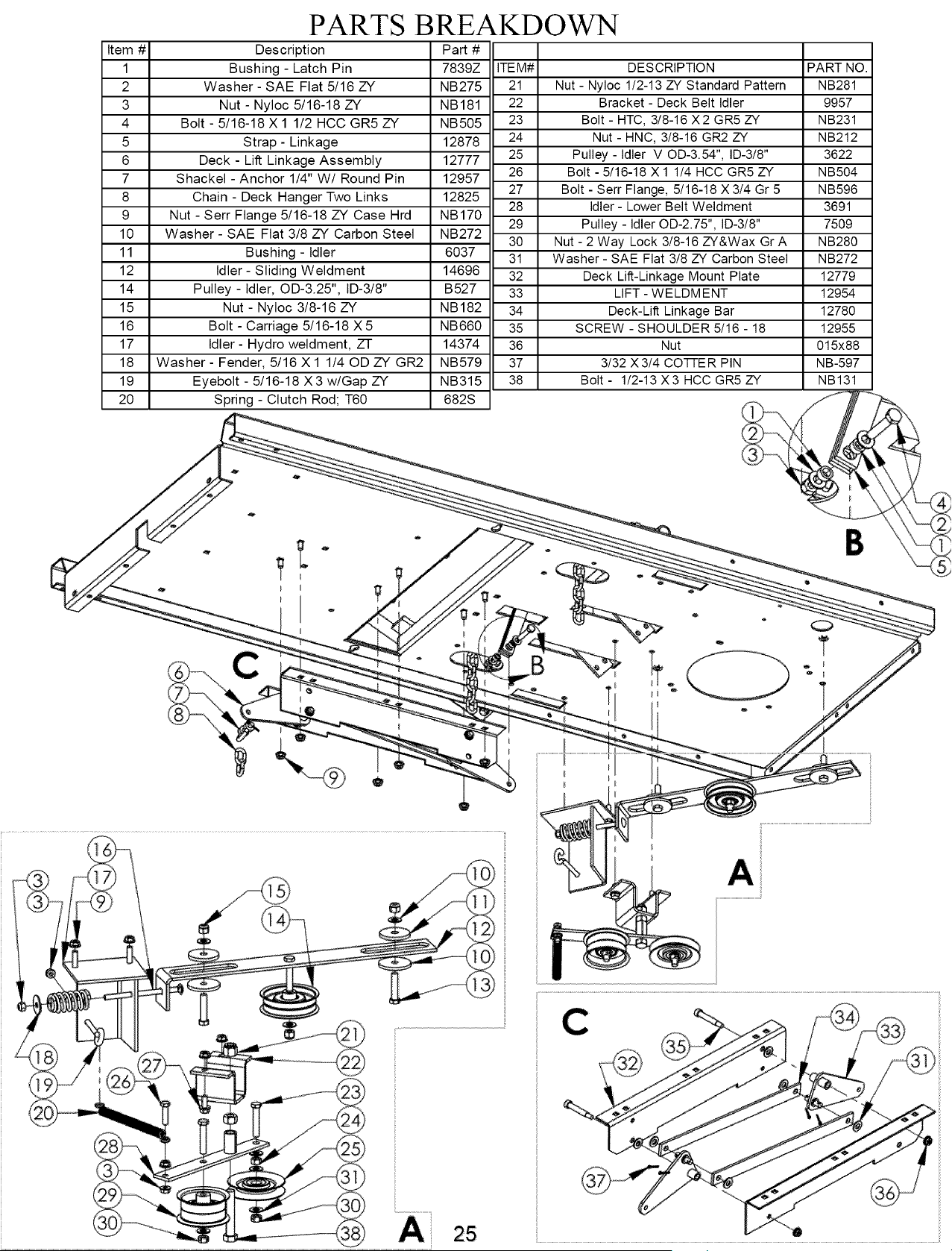
PARTS BREAKDOWN
Description Part #
Bushing - Latch Pin 7839Z ITEM#
Washer - SAE Flat 5/16 ZY NB275 21
Nut - Nyloc 5/16-18 ZY NB181 22
Bolt - 5/16-18 X 1 1/2 HCC GR5 ZY NB505 23
Strap- Linkage 12878 24
Deck - Lift Linkage Assembly 12777 25
Shackel - Anchor 1/4" W/ Round Pin 12957 26
27
Chain - Deck Hanger Two Links 12825
28
Nut - Serr Flange 5/16-18 ZY Case Hrd NB170
29
Washer - SAE Flat 3/8 ZY Carbon Steel NB272
30
Bushing - Idler 6037 31
Idler- Sliding Weldment 14696 32
Pulley - Idler, OD-3.25", ID-3/8" B527 33
Nut - Nyloc 3/8-16 ZY NB182 34
Bolt - Carriage 5/16-18 X 5 NB660 35
Idler - Hydro weldment, ZT 14374 36
Washer - Fender, 5/16 X 1 1/40D ZY GR2 NB579 37
Eyebolt - 5/16-18 X3 w/Gap ZY NB315 38
Spring - Clutch Rod; T60 682S
DESCRIPTION PART NO.
Nut - Nyloc 1/2-13 ZY Standard Pattern NB281
Bracket - Deck Belt Idler 9957
Bolt - HTC, 3/8-16 X2 GR5 ZY NB231
Nut - HNC, 3!8-16 GR2 ZY NB212
Pulley - Idler V OD-3.54", ID-3!8" 3622
Bolt - 5!16-18 X 1 1!4 HCC GR5 ZY NB504
Bolt - Serr Flange, 5!16-18 X 3!4 Gr 5 NB596
Idler - Lower Belt Weldment 3691
Pulley - Idler OD-2.75", ID-3!8" 7509
Nut - 2 Way Lock 3!8-16 ZY&Wax Gr A NB280
Washer - SAE Flat 3!8 ZY Carbon Steel NB272
Deck Lift-Linkage Mount Plate 12779
LIFT - WELDMENT 12954
Deck-Lift Linkage Bar 12780
SCREW - SHOULDER 5!16 - 18 12955
Nut 015x88
3!32 X 3!4 COTIE R PIN NB-597
Bolt - 1!2-13 X3 HCC GR5 ZY NB131
B
A
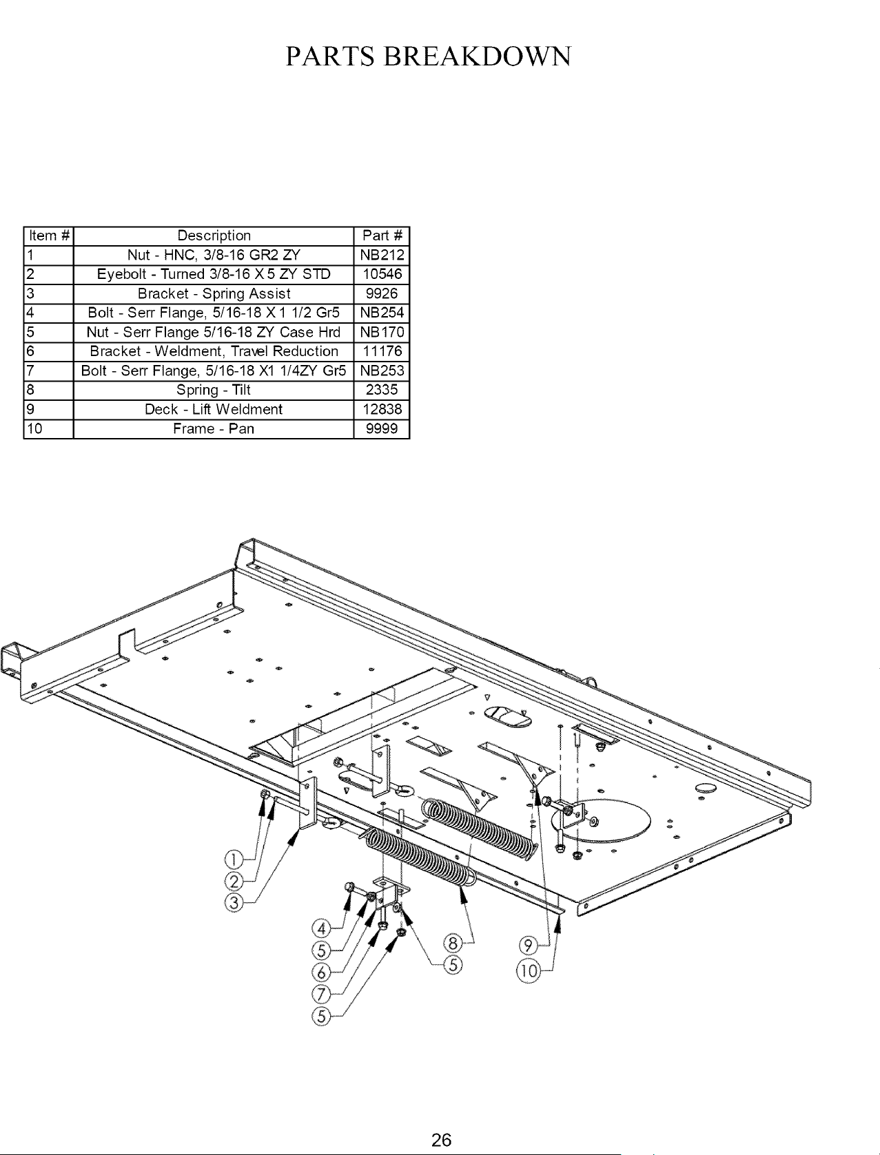
PARTS BREAKDOWN
Item # Description Part #
1 Nut - HNC, 3/8-16 GR2. ZY NB212
2 Eyebolt - Turned 3/8-16 X 5 ZY STD 10546
3 Bracket - Spring Assist 9926
4 Bolt - Serr Flange, 5/16-18 X 1 1/2 Gr5 NB254
5 Nut - Serr Flange 5/16-18 ZY Case Hrd NB170
6 Bracket - Weldment, Travel Reduction 11176
7 Bolt - Serr Flange, 5/16-18 X1 1/4ZY Gr5 NB253
8 Spring - Tilt 2335
9 Deck - Lift Weldment 12838
10 Frame - Pan 9999
26
PARTS BREAKDOWN
LIFT DETAIL
LIFT DETAIL
SEE (gAUGE WHEEL DETAIL "-_
SEE
Item #
1
2
3
4
5
6
7
8
9
10
11
12
13
14
15
16
17
18
19
20
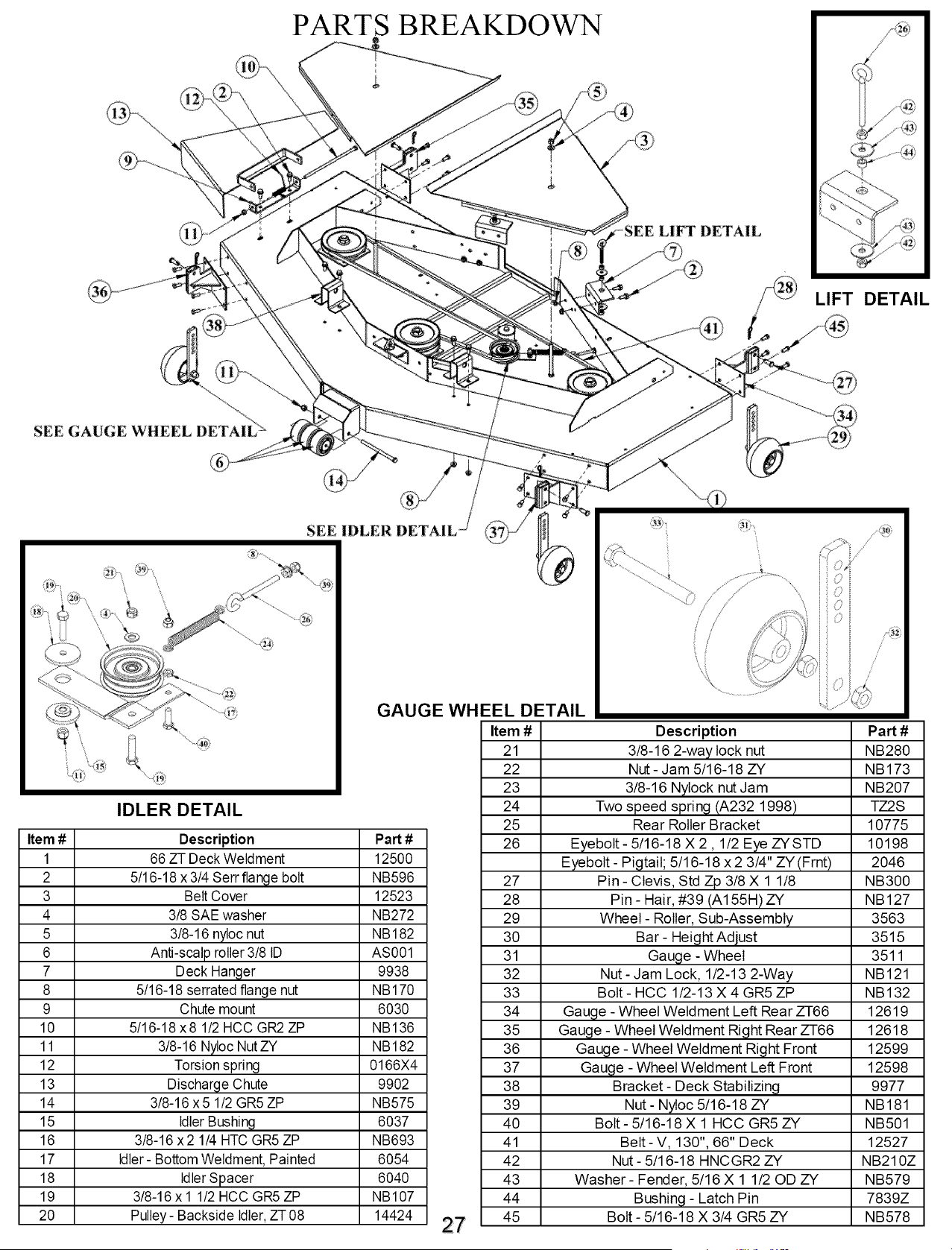
GAUGE
IDLER DETAIL
Description
66 ZT Deck Weldment
5/16-18 x 3/4 Serr flange bolt
Belt Cover
3/8 SAE washer
3/8-16 nyloc nut
Anti-scalp roller 3/8 ID
Deck Hanger
5/16-18 serrated flange nut
Chute mount
5/16-18 x8 1/2 HCC GR2 ZP
3/8-16 Nyloc Nut ZY
Torsion spring
Discharge Chute
3/8-16 x5 1/2 GR5 ZP
Idler Bushing
3/8-16 x2 1/4 HTC GR5 ZP
Idler- Bottom Weldment, Painted
Idler Spacer
3/8-16 x 1 1/2 HCC GR5 ZP
Pulley- Backside Idler,ZT 08
Part #
12500
NB596
12523
NB272
NB182
AS001
9938
NB170
6030
NB136
NB182
0166X4
9902
NB575
6037
NB693
6054
6040
NB107
14424
EEL DETAIL
Item #
21
22
23
24
25
26
27
28
29
30
31
32
33
34
35
36
37
38
39
40
41
42
43
44
45
Description Part #
3/8-16 2-way lock nut NB280
Nut- Jam 5/16-18 ZY NB173
3/8-16 Nylock nut Jam NB207
Two speed spring (A232 1998) TZ2S
Rear Roller Bracket 10775
Eyebolt- 5/16-18 X 2,1/2 Eye ZYSTD 10198
Eyebolt- Pigtail; 5/16-18 x 2 3/4" ZY (Frnt) 2046
Pin - Clevis, Std Zp 3/8 X 1 1/8 NB300
Pin - Hair, #39 (A155H) ZY NB127
Wheel- Roller, Sub-Assembly 3563
Bar- Height Adjust 3515
Gauge - Wheel 3511
Nut- Jam Lock, 1/2-13 2-Way NB121
Bolt- HCC 1/2-13 X 4 GR5 ZP NB132
Gauge - Wheel Weldment Left Rear ZT66 12619
Gauge - Wheel Weldment Right Rear ZT66 12618
Gauge - Wheel Weldment Right Front 12599
Gauge - Wheel Weldment Left Front 12598
Bracket- Deck Stabilizing 9977
Nut - Nyloc 5/16-18 ZY NB181
Bolt- 5/16-18 X 1 HCC GR5 ZY NB501
Belt- V, 130", 66" Deck 12527
Nut - 5/16-18 HNCGR2 ZY NB210Z
Washer- Fender, 5/16 X 1 1/20D ZY NB579
Bushing - Latch Pin 7839Z
Bolt- 5/16-18 X 3/4 GR5 ZY NB578
PARTS BREAKDOWN
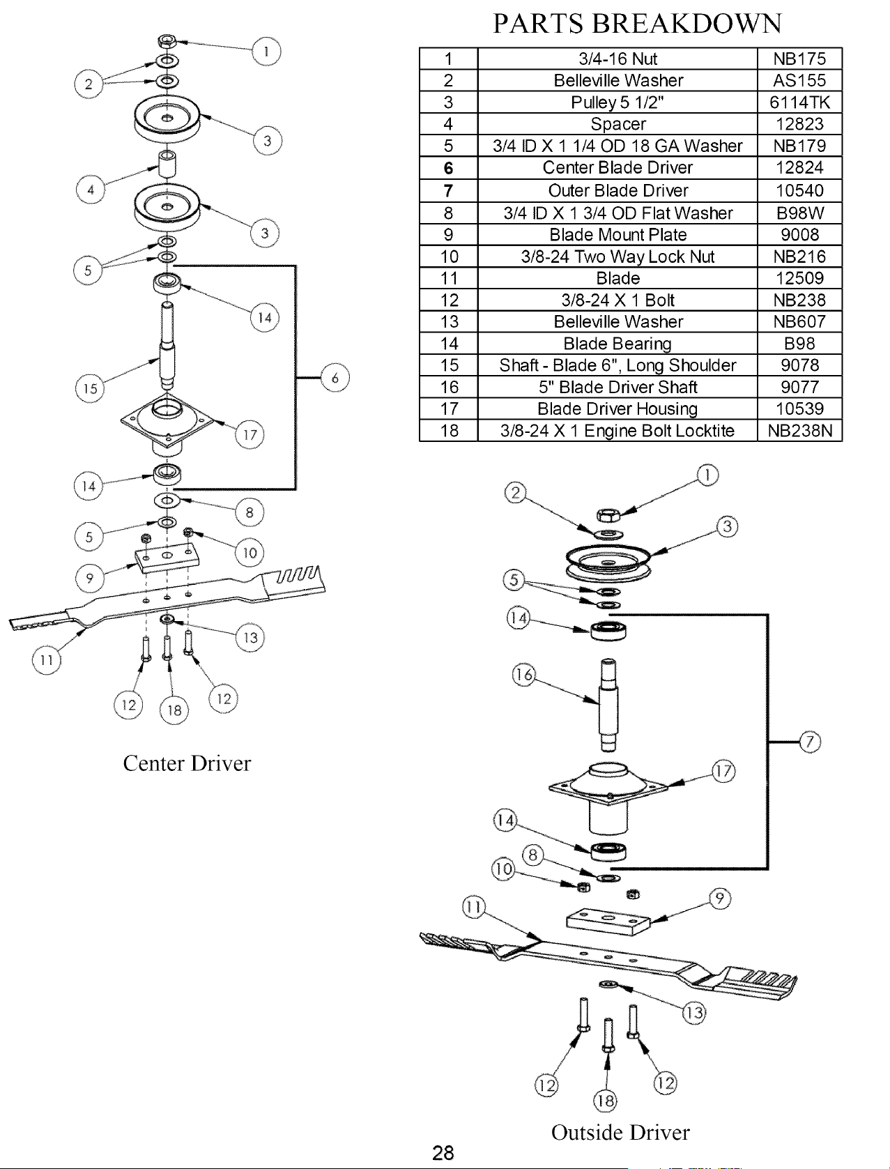
1 3/4-16 Nut NB175
2 Belleville Washer AS155
3 Pulley 5 1/2" 6114TK
4 Spacer 12823
5 3/4 ID X 1 1/40D 18 GA Washer NB179
6 Center Blade Driver 12824
7 Outer Blade Driver 10540
8 3/4 ID X 1 3/40D Flat Washer B98W
9 Blade Mount Plate 9008
10 3/8-24 Two Way Lock Nut NB216
11 Blade 12509
12 3/8-24 X 1 Bolt NB238
13 Belleville Washer NB607
14 Blade Beari ng B98
15 Shaft- Blade 6", Long Shoulder 9078
16 5" Blade Driver Shaft 9077
17 Blade Driver Housing 10539
18 3/8-24 X 1 Engine Bolt Locktite NB238N
Center Driver
28
Outside Driver
Item #
1
2
3
4
5
6
7
8
9
10
11
12
13
14
15
16
17
18
PARTS BREAKDOWN
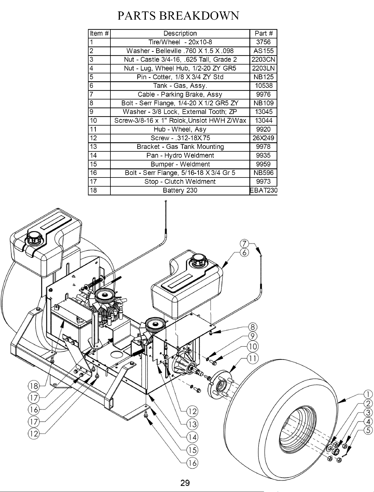
Description Part #
Tire/Wheel - 20x10-8 3756
Washer - Belleville .760 X 1.5 X .098 AS155
Nut - Castle 3/4-16, .625 Tall, Grade 2 2203CN
Nut - Lug, Wheel Hub, 1/2-20 ZY GR5 2203LN
Pin - Cotter, 1/8 X3/4 ZY Std NB125
Tank - Gas, Assy. 10538
Cable - Parking Brake, Assy 9976
Bolt - Serr Flange, 1/4-20 X 1/2 GR5 ZY NB109
Washer- 3/8 Lock, External Tooth; ZP 13045
Screw-3/8-16 x 1" Rolok,Unslot HWH Z/Wax 13044
Hub - Wheel, Asy 9920
Screw - .312-18X75 26X249
Bracket - Gas Tank Mounting 9978
Pan - Hydro Weldment 9935
Bumper- Weldment 9959
Bolt - Serr Flange, 5/16-18 X 3/4 Gr 5 NB596
Stop - Clutch Weldment 9973
Battery 230 --BAT23(
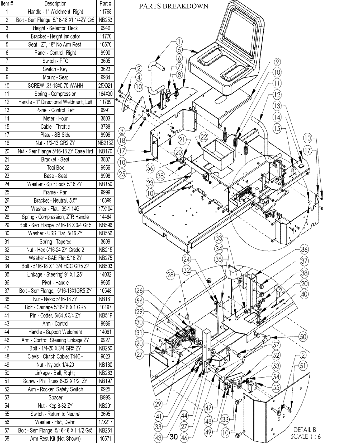
1 11768
2 NB253
3 9940
4 11770
5 10570
6 9990
7 3605
8 3623
9 9984
10 25X021
11 164X30
12 11769
13 9991
14 3803
15 3788
17 9996
18 NB213Z
20 NB170
21 3807
22 9956
23 9998
24 NB159
25 9999
26 10899
27 17)<104
28 14464
29 NB596
30 NB556
31 3609
32 NB215
33 NB275
34 NB503
35 14032
36 9985
37 10548
38 NB181
40 10197
41 NB519
43 9986
44 14061
46 9927
47 NB250
48 9023
49 NB180
50 NB263
51 NB197
52 9925
53 B99S
54 NB201
55 3695
56 17)(217
57 NB254
Description
Handle-1"Weldment,Right
Bolt-SerrFlange,5/16-18X11/4ZYGr5
Height-Selector,Deck
Bracket-HeightIndicator
Seat-ZT,18"NoArmRest
Panel-Control,Right
Switch-PTO
Switch-Key
Mount-Seat
SCREW.31-18X0.75WAHH
Spring-Compression
Handle-1"DirectionalWeldment,Left
Panel-Control,Left
Meter-Hour
Cable-Throttle
Plate-SBSide
Nut-1/2-13GR2ZY
Nut-SerrFlange5/16-18ZYCaseHrd
Bracket-Seat
ToolBox
Base-Seat
Washer-SplitLock5/16ZY
Frame-Pan
Bracket-Neutral,5.5"
Washer-Flat, 39-114G
Spring-Compression;ZTRHandle
Bolt- SerrFlange,5/16-18X3/4Gr5
Washer-USSFlat,5/16ZY
Spring-Tapered
Nut- Hex5/16-24ZYGrade2
Washer-SAEFlat5/16ZY
Bolt-5/16-18X1 3/4HCCGR5ZP
Linkage-Steering'9"X1.25"
Pivot-Handle
Bolt- SerfFlange,5/16-18X1GR5ZY
Nut-Nyloc5/16-18ZY
Bolt- Carriage5/16-18X 1GR5
Pin-Cotter,5/64X3/4ZY
Arm- Control
Handle-SupportWeldment
Arm- Control,SteeringLinkageZY
Bolt- 1/4-20X3/4GR5ZY
Clevis-ClutchCable;T44CH
Nut- Nylock1/4-20
Linkage-Ball,Right;
Screw-PhilTruss8-32X1/2 ZY
Arm- Rocker,SafetySwitch
Spacer
Nut-Kep8-32ZY
Switch-Returnto Neutral
Washer-Flat,Delrin
Bolt- SerfFlange,5/16-18X1 1/2Gr5
ArmRestKit(NotShown)
PARTS BREAKDOWN
DETAIL B
SCALE 1 : 6
BREAKDOWN
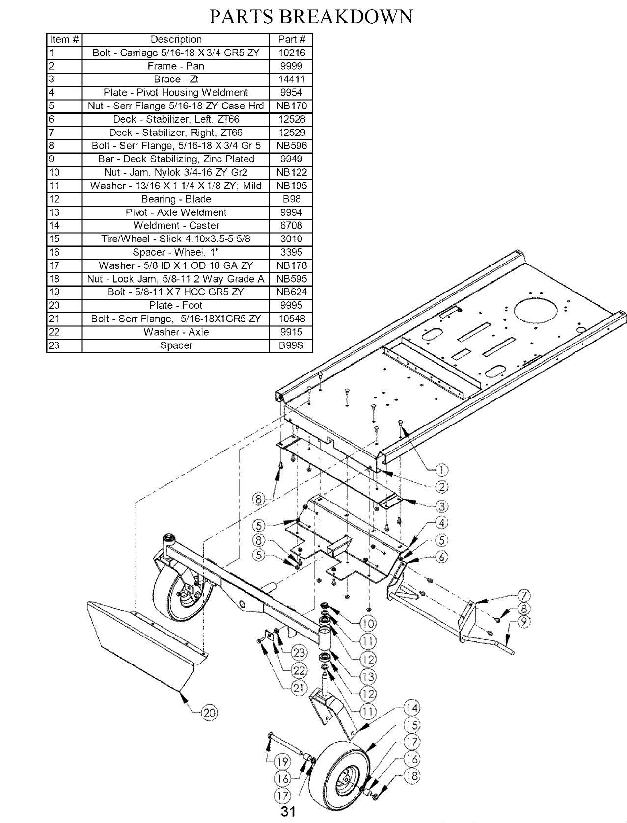
Item # Description Part #
1 Bolt - Carriage 5/16-18 X3/4 GR5 ZY 10216
2 Frame - Pan 9999
3 Brace - Zt 14411
4 Plate - Pivot Housing Weldment 9954
5 Nut - Serr Flange 5/16-18 ZY Case Hrd NB170
6 Deck- Stabilizer, Left, ZT66 12528
7 Deck- Stabilizer, Right, ZT66 12529
8 Bolt - Serr Flange, 5/16-18 X 3/4 Gr 5 NB596
9 Bar- Deck Stabilizing, Zinc Plated 9949
10 Nut - Jam, Nylok 3/4-16 ZY Gr2 NB122
11 Washer- 13/16 X1 1/4 Xl/8 ZY; Mild NB195
12 Bearing - Blade B98
13 Pivot - Axle Weldment 9994
14 Weldment - Caster 6708
15 Tire/Wheel - Slick 4.10x3.5-5 5/8 3010
16 Spacer - Wheel, 1" 3395
17 Washer - 5/8 ID X 10D 10 GA ZY NB178
18 Nut - Lock Jam, 5/8-11 2 Way Grade A NB595
19 Bolt - 5/8-11 X7 HCC GR5 ZY NB624
20 Plate - Foot 9995
21 Bolt - Serr Flange, 5/16-18X1GR5 ZY 10548
22 Washer - Axle 9915
23 Spacer B99S
PARTS
/
t
J
31
PARTS BREAKDOWN
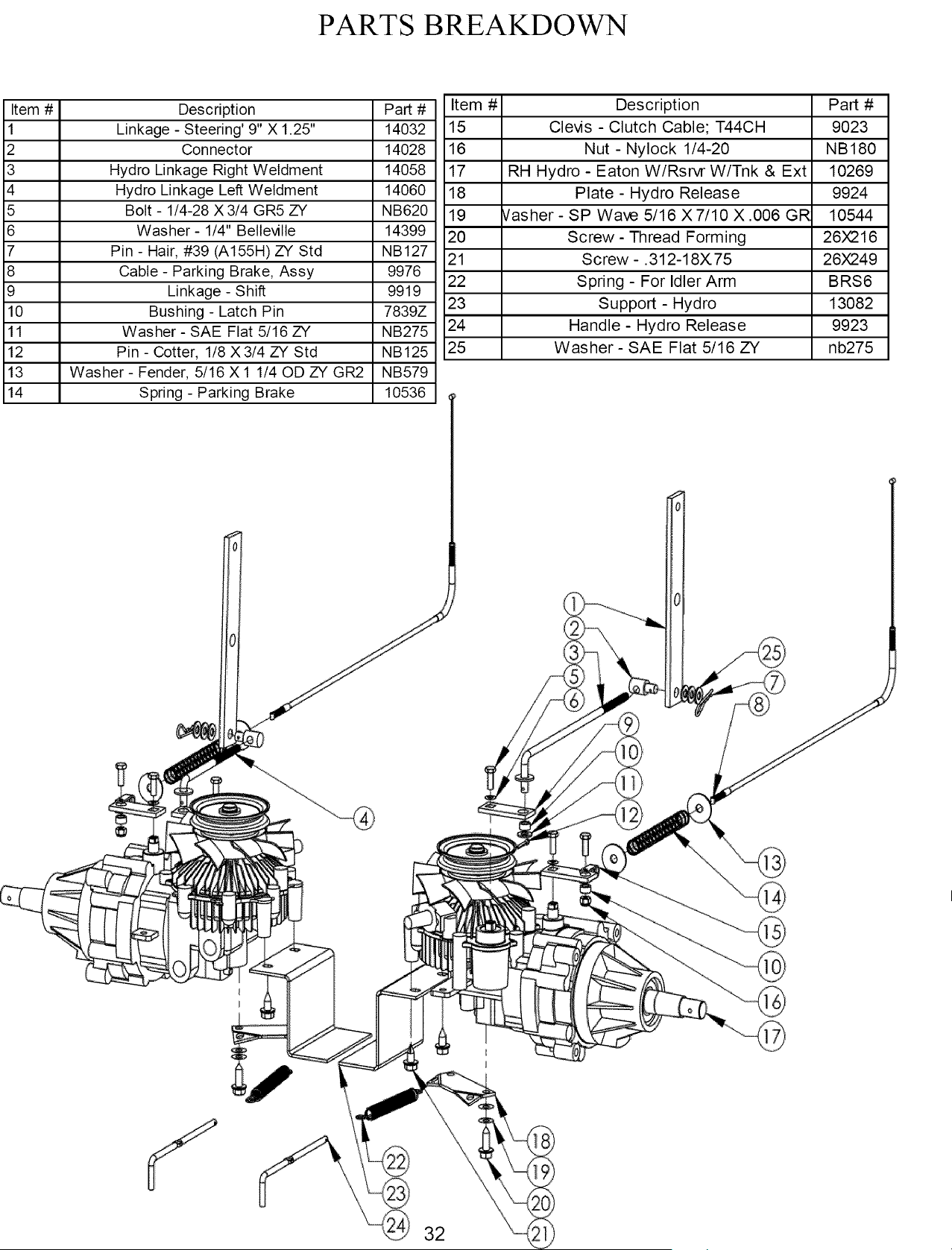
Item # Description Part #
1 Linkage - Steering' 9" X 1.25" 14032
2 Connector 14028
3 Hydro Linkage Right Weldment 14058
4 Hydro Linkage Left Weldment 14060
5 Bolt - 1/4-28 X 3/4 GR5 ZY NB620
6 Washer- 1/4" Belleville 14399
7 Pin - Hair, #39 (A155H) ZY Std NB127
8 Cable - Parking Brake, Assy 9976
9 Linkage - Shift 9919
10 Bushing - Latch Pin 7839Z
11 Washer - SAE Flat 5/16 ZY NB275
12 Pin - Cotter, 1/8 X3/4 ZY Std NB125
13 Washer- Fender, 5/16 X 1 1/40D ZY GR2 NB579
14 Spring - Parking Brake 10536
Item # Description Part #
15 Clevis - Clutch Cable; T44CH 9023
16 Nut - Nylock 1/4-20 NB180
17 RH Hydro - Eaton W/Rsrvr W/Tnk & Ext 10269
18 Plate - Hydro Release 9924
19 rasher- SP Wave 5/16 X7/10 X.006 GR 10544
20 Screw - Thread Forming 26)(216
21 Screw -. 312-18X. 75 26X249
22 Spring - For Idler Arm BRS6
23 Support - Hydro 13082
24 Handle - Hydro Release 9923
25 Washer - SAE Flat 5/16 ZY nb275
32
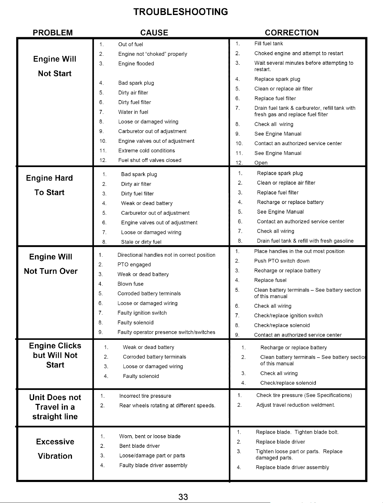
TROUBLESHOOTING
PROBLEM
Engine Will
Not Start
Engine Hard
To Start
Engine Will
Not Turn Over
Engine Clicks
but Will Not
Start
Unit Does not
Travel in a
straight line
Excessive
Vibration
1.
2.
3.
4.
5.
6.
7.
8.
9.
10.
11.
12.
1.
2.
3.
4.
5.
6.
7.
8.
1.
2.
CAUSE
Out of fuel
Engine not "choked" properly
Engine flooded
Bad spark plug
Dirty air filter
Dirty fuel filter
Water in fuel
Loose or damaged wiring
Carburetor out of adjustment
Engine valves out of adjustment
Extreme cold conditions
Fuel shut off valves closed
Bad spark plug
Dirty air filter
Dirty fuel filter
Weak or dead battery
Carburetor out of adjustment
Engine valves out of adjustment
Loose or damaged wiring
Stale or dirty fuel
Directional handles not in correct position
PTO engaged
CORRECTION
1. Fill fuel tank
2. Choked engine and attempt to restart
3. Wait several minutes before attempting to
restart.
4. Replace spark plug
5. Clean or replace air filter
6. Replace fuel filter
7. Drain fuel tank & carburetor, refill tank with
fresh gas and replace fuel filter
8. Check all wiring
9. See Engine Manual
10. Contact an authorized service center
11. See Engine Manual
12. Open
1. Replace spark plug
2. Clean or replace air filter
3. Replace fuel filter
4. Recharge or replace battery
5. See Engine Manual
6. Contact an authorized service center
7. Check all wiring
8. Drain fuel tank & refill with fresh gasoline
1. Place handles in the out most position
2. Push PTO switch down
3.
4.
5.
6.
7.
8.
Weak or dead battery
Blown fuse
Corroded battery terminals
Loose or damaged wiring
Faulty ignition switch
Faulty solenoid
3.
4.
5.
6.
7.
8.
Recharge or replace battery
Replace fusel
Clean battery terminals - See battery section
of this manual
Check all wiring
Check/replace ignition switch
Check/replace solenoid
1.
2.
3.
4.
1.
2.
1.
2.
3.
4.
Faulty operator presence switch/switches
Weak or dead battery
Corroded battery terminals
Loose or damaged wiring
Faulty solenoid
Incorrect tire pressure
Rear wheels rotating at different speeds.
Worn, bent or loose blade
Bent blade driver
Loose/damage part or parts
Faulty blade driver assembly
9. Contact an authorized service center
1. Recharge or replace battery
2. Clean battery terminals - See battery sectio
of this manual
3. Check all wiring
4. Check/replace solenoid
1. Check tire pressure (See Specifications)
2. Adjust travel reduction weldment.
1.
2.
3.
Replace blade. Tighten blade bolt.
Replace blade driver
Tighten loose part or parts. Replace
damaged parts.
Replace blade driver assembly

TROUBLESHOOTING Continued
PROBLEM
Loss of
Power
Engine
backfires when
turning engine
OFF
Poor cut -
uneven
Poor cut -
uneven
Battery will
not charge
Loss of drive
CAUSE
1. Cutting too much grass/too fast
2. "Choke" position
3. Buildup of grass, leaves and trash under
deck.
4. Dirty air filter
5. Low oil level/dirty oil
6. Faulty spark plug
7. Dirty fuel filter
8. Stale or dirty fuel
9. Water in fuel
10. Spark plug wire loose
11. Dirty engine air screen/fins
12. Dirty/clogged muffler
13. Loose or damaged wiring
14. Carburetor out of adjustment
15. Engine valves out of adjustment
16. Loose drive belt
Engine throttle control not set at "SLOW"
position for 30 seconds before stopping
engine.
1. Worn, bent or loose blade
2. Mower deck not level
3. Buildup of debris under deck.
4. Bent deck
5. Faulty Blade driver assembly
1. Worn, bent or loose blade
2. Mower deck not level
3. Buildup of grass, leaves and trash under
deck.
4. Bent deck
5. Faulty Blade driver assembly
1. Bad battery
2. Poor cable connections
3. Faulty solenoid
1.
2.
3.
Bypass linkages in the bypass position
Hydro belt worn, damaged, or broken
Idler spring loose or broken
1.
2.
3.
4.
5.
6.
7.
8.
9.
10.
11.
12.
13.
14.
15.
16.
1.
1.
2.
3.
4.
5.
1.
2.
3.
4.
5.
1.
2.
3.
1.
2.
3.
CORRECTION
Set in High Cut (position 8)/reduce speed
Push choke control in
Clean underside of mower deck
Clean or replace air filter
Check oil level/change oil
Clean and re-gap or change plug
Replace fuel filter
Drain fuel tank & refill tank with fresh gas
Drain fuel tank & carburetor, refill tank with
fresh gas and replace fuel filter
Connect and tighten spark plug wire
Clean engine air screen/fins
Clean/replace muffler
Check all wiring
See Engine Manual
Contact an authorized service center
Adjust idler/replace belt
Move throttle control to "SLOW" position and
allow to idle for 30 seconds before stopping
engine
Replace blade. Tighten blade bolt
Level deck. See section in this manual
Clean underside of mower deck
Replace deck
Replace blade driver assembly
Replace blade. Tighten blade bolt
Level deck. See section in this manual
Clean underside of mower deck
Replace deck
Replace blade driver assembly
Replace battery
Check/clean all connections. See section in
this manual
Replace solenoid
Make sure that the bypass linkages are in
the drive or engaged position. Located at
the rear of the machine. Refer to decal on
the rear of the unit.
Replace Hydro belt.
Replace Idler spring
34
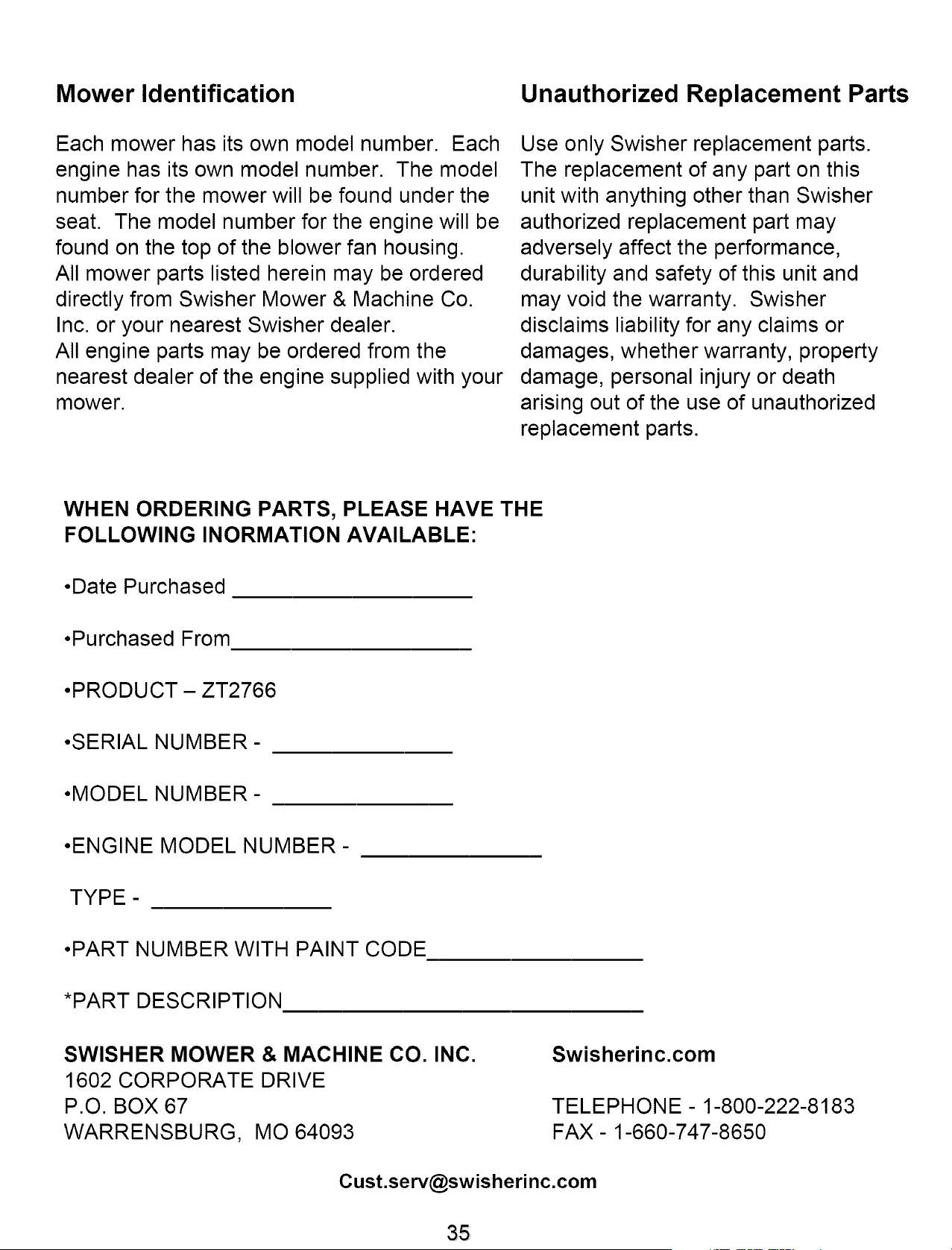
Mower Identification Unauthorized Replacement Parts
Each mower has its own model number. Each
engine has its own model number. The model
number for the mower will be found under the
seat. The model number for the engine will be
found on the top of the blower fan housing.
All mower parts listed herein may be ordered
directly from Swisher Mower & Machine Co.
Inc. or your nearest Swisher dealer.
All engine parts may be ordered from the
nearest dealer of the engine supplied with your
mower.
Use only Swisher replacement parts.
The replacement of any part on this
unit with anything other than Swisher
authorized replacement part may
adversely affect the performance,
durability and safety of this unit and
may void the warranty. Swisher
disclaims liability for any claims or
damages, whether warranty, property
damage, personal injury or death
arising out of the use of unauthorized
replacement parts.
WHEN ORDERING PARTS, PLEASE HAVE THE
FOLLOWING INORMATION AVAILABLE:
•Date Purchased
•Purchased From
•PRODUCT - ZT2766
•SERIAL NUMBER-
•MODEL NUMBER-
•ENGINE MODEL NUMBER -
TYPE-
•PART NUMBER WITH PAINT CODE
*PART DESCRIPTION
SWISHER MOWER & MACHINE CO. INC.
1602 CORPORATE DRIVE
P.O. BOX 67
WARRENSBURG, MO 64093
Swisherinc.com
TELEPHONE - 1-800-222-8183
FAX- 1-660-747-8650
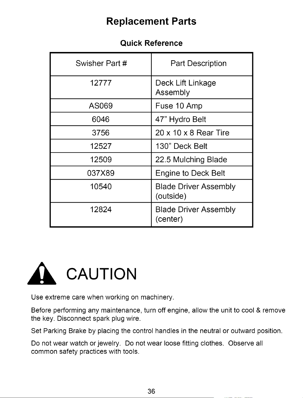
Replacement Parts
Quick Reference
Swisher Part #
12777
AS069
6046
3756
12527
12509
037X89
10540
12824
Part Description
Deck Lift Linkage
Assembly
Fuse 10 Amp
47" Hydro Belt
20 x 10 x 8 Rear Tire
130" Deck Belt
22.5 Mulching Blade
Engine to Deck Belt
Blade Driver Assembly
(outside)
Blade Driver Assembly
(center)
CAUTION
Use extreme care when working on machinery.
Before performing any maintenance, turn off engine, allow the unit to cool & remove
the key. Disconnect spark plug wire.
Set Parking Brake by placing the control handles in the neutral or outward position.
Do not wear watch or jewelry. Do not wear loose fitting clothes. Observe all
common safety practices with tools.
36
WARRANTY RIGHTS AND OBLIGATIONS
YOUR WARRANTY RIGHTS AND OBLIGATIONS: The California Air Resources Board and Swisher Mower, is pleased to
explain the evaporative emission control system (EECS) on your model year 2006 and later Swisher Product. In California,
new Outdoor Power Equipment, must be designed, built and equipped to meet the State's stringent anti-smog standards.
Swisher Mower must warrant the EECS on your Power Equipment, for the period of time listed below provided there has
been no abuse, neglect, or improper maintenance. For model year 2006 the EECS on your mower includes the liquid fuel
lines, fuel line connectors, and fuel line clamps. Where a warrantable condition exists, Swisher Mower will repair at no cost
to you. Expenses covered under warranty include diagnosis, parts, and labor.
MANUFACTURER'S WARRANTY COVERAGE: For a period of two years, any evaporative emission-related part included
in the list of EECS parts for your mower is defective, the part will be repaired or replaced by Swisher Mower.
OWNER'S WARRANTY RESPONSIBILITIES: As the owner of this Power Equipment, you are responsible for performance
of the required maintenance listed in your owner's manual. Swisher Mower recommends that you retain all receipts
covering maintenance on your Power Equipment, but Swisher Mower cannot deny warranty solely for the lack of receipts.
As the Power Equipment owner, you should be aware that Swisher Mower, may deny you warranty coverage if your Power
Equipment, or a covered part has failed due to abuse, neglect, or improper maintenance, unapproved modifications, or the
use of parts not made or approved by the equipment manufacturer. You are responsible for presenting your Power
Equipment to an authorized Swisher Service center as soon as the problem exists. Warranty repairs should be completed
in a reasonable amount of time, not to exceed 30 days. If you have a question regarding your warranty rights and
responsibilities, you should contact the Swisher Mower Service representative at 1-800-222-8183.
WARRANTY COMMENCEMENT DATE: The warranty period begins on the date the Power Equipment Is purchased.
LENGTH OF COVERAGE: This warranty shall be for a period of two (2) years from the initial date of purchase.
WHAT IS COVERED: Warranted parts include the Liquid fuel line, fuel line connectors, and fuel line clamps.
REPAIR OR REPLACEMENT OF PARTS: Repair or replacement of any evaporative warranted part will be performed at
no charge to the owner at an authorized Swisher Mower Service Center. If you have a question regarding your warranty
rights and responsibilities, you should contact your nearest authorized service center or call the Swisher Mower Service
representative at 1-800-222-8183.
WARRANTY PERIOD: Any warranted part is not scheduled for replacement as required maintenance, or which is
scheduled only for regular inspection to the effect of "repair or replace as necessary" shall be warranted for two (2) years.
Any warranted part that is scheduled for replacement as required maintenance shall be warranted for the period of time up
to the first scheduled replacement point for that part.
DIAGNOSIS: The owner shall not be charged for diagnostic labor that leads to the determination that a warranted part is
defective if the diagnostic work is performed at an authorized Swisher Service Center.
CONSEQUENTIAL DAMAGE: Swisher Mower, may be liable for damages to other engine or equipment components
caused by the failure of a warranted part still under warranty.
WHAT IS NOT COVERED: All failures caused by abuse, neglect, or improper maintenance is not covered.
ADD-ON OR MODIFIED PARTS: The use of add-on or modified parts may be grounds for disallowing a warranty claim.
Swisher Mower is not liable to cover failures of warranted parts caused by the use of an add-on or modified part.
HOW TO FILE A CLAIM: If you have a question regarding your warranty rights and responsibilities, you should contact your
nearest authorized service center or call Swisher Mower Service representative at 1-800-222-8183.

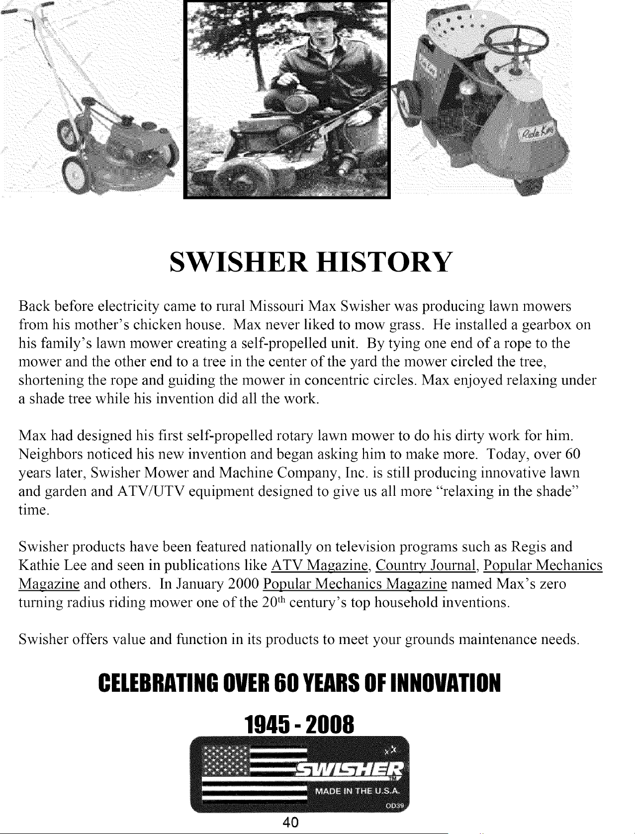
SWISHER HISTORY
Back before electricity came to rural Missouri Max Swisher was producing lawn mowers
from his mother's chicken house. Max never liked to mow grass. He installed a gearbox on
his family's lawn mower creating a self-propelled unit. By tying one end of a rope to the
mower and the other end to a tree in the center of the yard the mower circled the tree,
shortening the rope and guiding the mower in concentric circles. Max enjoyed relaxing under
a shade tree while his invention did all the work.
Max had designed his first self-propelled rotary lawn mower to do his dirty work for him.
Neighbors noticed his new invention and began asking him to make more. Today, over 60
years later, Swisher Mower and Machine Company, Inc. is still producing innovative lawn
and garden and ATV/UTV equipment designed to give us all more "relaxing in the shade"
time.
Swisher products have been featured nationally on television programs such as Regis and
Kathie Lee and seen in publications like ATV Ma_azine, Country Journal, Popular Mechanics
Magazine and others. In January 2000 Popular Mechanics Magazine named Max's zero
turning radius riding mower one of the 20 th century's top household inventions.
Swisher offers value and function in its products to meet your grounds maintenance needs.
CELEBRATINGOVER60 YEARSOFINNOVATION
1945- 2008
40