f
swisherinc.com
OWNER'S
MANUAL
MODEL NO.
ZT1436B
ZT18542
ZT2250
IMPORTANT
Read and follow all
SafeR" Precautions
and Instructions
before operating this
equipment.
Rev. 06-039
J
?
"Z"SERIES
ZEROTURNHYDROSTATICDRIVE
Assembly
Operation
Service and Adjustment
Repair Parts
(
1602 CORPORATE DRIVE, P.O. BOX 67, WARRENSBURG, MISSO[ RI 64093
PHONE 660-747-8183 FAX 660-747-8650
Manufacturing quality lawn care equipment since 1945
Made In The ]
USA
J
ONZTR04
LIMITED WARRANTY
The manufacturer's warranty to the original consumer purchaser is: This product is free from defects
in materials and workmanship for a period of two (2) years from the date of purchase by the original
consumer purchaser. We will repair or replace, at our discretion, parts found to be defective due to
materials or workmanship. This warranty is subject to the following limitations and exclusions:
1) Engine Warranty All engines utilized on our products have a separate warranty extended
to them by the individual engine manufacturer. Any engine service
difficulty is the responsibility of the engine manufacturer and in no way
is Swisher Mower Co., Inc. or its agents responsible for the engine
warranty. The Briggs & Stratton Engine Service Hot-Line is 1-800-233-
3723. The Tecumseh Engine Service Hot-Line is 1-800-558-5402.
2) Commercial Use This product is not intended for commercial use and carries no
commercial warranty.
3) Limitation This warranty applies only to products which have been properly
assembled, adjusted, and operated in accordance with the instructions
contained within this manual. This warranty does not apply to any
product of Swisher Mower Co., Inc., that has been subject to alteration,
misuse, abuse, improper assembly or installation, shipping damage, or to
normal wear of the product.
4) Exclusions Excluded from this warranty are normal wear, normal adjustments, and
normal maintenance.
In the event you have a claim under this warranty, you must return the product to an authorized
service dealer. All transportation charges, damage, or loss incurred during transportation of parts
submitted for replacement or repair under this warranty shall be borne by the purchaser. Should you
have any questions concerning this warranty, please contact us toll-free at 1-800-222-8183. The
model number, serial number, date of purchase, and the name of the authorized Swisher dealer from
whom you purchased the mower will be needed before any warranty claim can be processed.
THIS WARRANTY DOES NOT APPLY TO ANY INCIDENTAL OR CONSEQUENTIAL
DAMAGES AND ANY IMPLIED WARRANTIES ARE LIMITED TO THE SAME TIME
PERIODS STATED HERE1N FOR ALL EXPRESSED WARRANTIES. Some states do not allow
the limitation of consequential damages or limitations on how long an implied warranty may last, so
the above limitations or exclusions may not apply to you. This warranty gives you specific legal
rights and you may have other rights, which vary from state-to-state. This is a limited warranty as
defined by the Magnuson-Moss Act of 1975.
TABLE OF CONTENTS
WARRANTY .......................... 2
INTRODUCTION .................... 3
SAFETY .............................. 3-6
AS SEMBLY/OPERATION ........ 7-8
MAINTENANCE .................. 9-10
SERVICE / ADJUSTMENT ............. 11-14
WIR1NG DIAGRAM ...................... 15
PARTS BREAKDOWN .................. 16-28
TROUBLESHOOTING .................... 29
SLOPE GUIDE .............................. 30
,J
Thank you for choosing Swisher's Zero Turn Rider Mower. Before
operating your mower, please read, understand and follow all of the safety
precautions and other instructions explained in this manual. As with all power
equipment, lawnmowers can be potentially dangerous if improperly used.
J
SAFETY PRECAUTIONS & DECALS
This Safety Alert Symbol indicates important messages in this
manual. When you see this symbol, carefully read the message that
follows and be alert to the possibility of personal injury.
Read this manual completely. This machine can amputate hands and feet, and
throw objects. Failure to observe the following safety instructions could result in
serious injury or death.
• Read the manual. Learn to operate this machine safely.
• Always disconnect the spark plug wire and place the wire where it cannot contact the
spark plug, to prevent accidental starting the engine when setting up, transporting,
adjusting or making repairs.
• Keep all shields and guards in place.
• Understand the speed, steering and stability of this machine. Know the positions and
operations of all controls before you operate this machine. Check all of the controls in
a safe area before starting to work with this machine.
• Allow only responsible adults who are familiar with these instructions to operate this
machine. Never allow children to operate this machine.
• Clear the area of objects such as rocks, toys, wire, etc. that can be picked up and
thrown by the blade.
• Be sure the area is clear of other people before mowing. Be aware of the mower
discharge direction and do not point at anyone. Stop the machine if anyone enters the
mowing area. Children are often attracted to the machine and the mowing activity.
Never assume that chiMren Hqll remain where you last saw them. Keep children
under the watchful care of another responsible adult.
• No riders!
• Do not put hands or feet near or under rotating parts. Keep clear of the discharge
opening at all times.
• Do not mow in reverse. Always look down and behind before and during backing.
I0
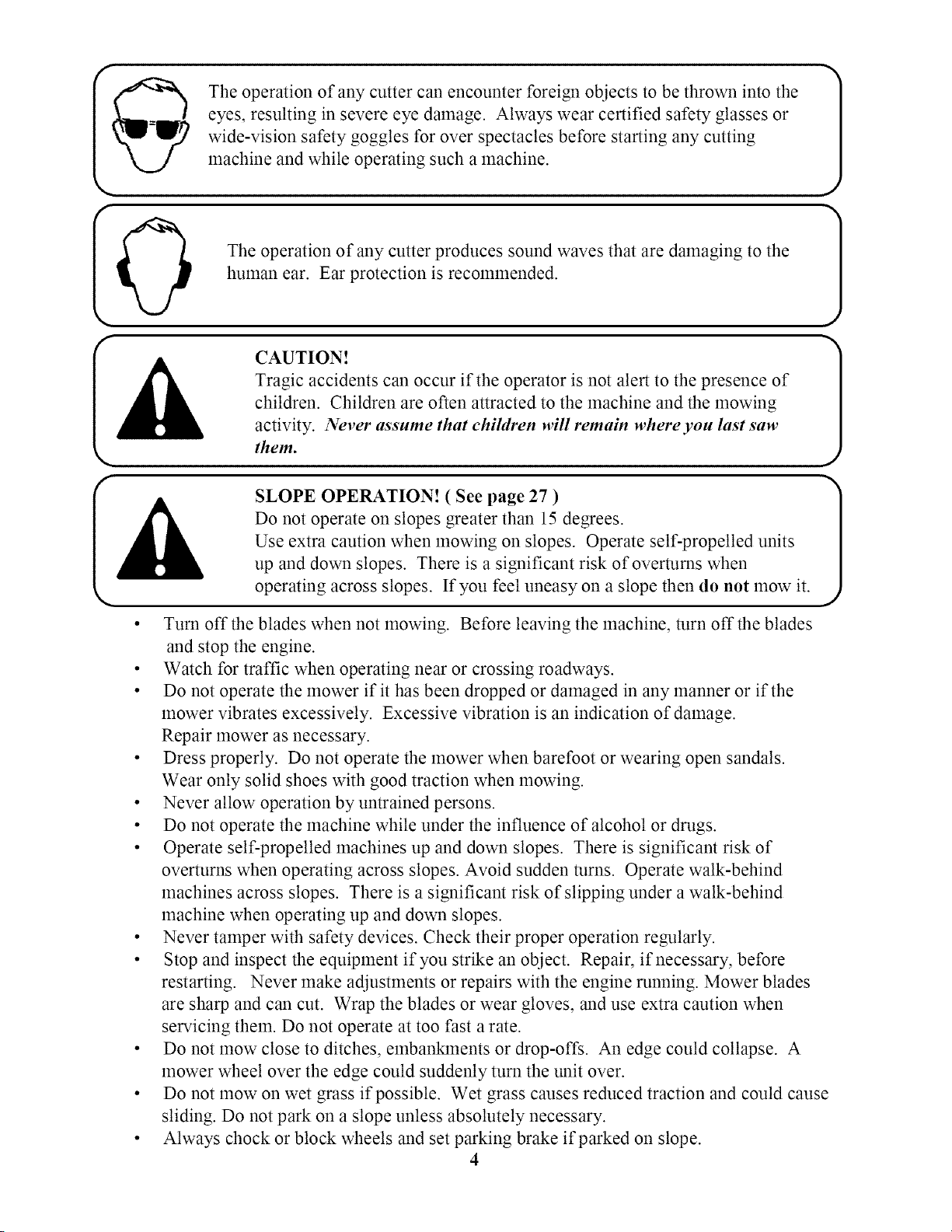
The operation of any cutter can encounter foreign objects to be thrown into the
eyes, resulting in severe eye damage. Always wear certified safety glasses or
wide-vision safety goggles for over spectacles before starting any cutting
machine and while operating such a machine.
The operation of any cutter produces sound waves that are damaging to the
human ear. Ear protection is recommended.
CAUTION!
Tragic accidents can occur if the operator is not alert to the presence of
children. Children are often attracted to the machine and the mowing
activity. Never assume that chiMren Hill remain where you last saw
them.
SLOPE OPERATION! ( See page 27 )
Do not operate on slopes greater than 15 degrees.
Use extra caution when mowing on slopes. Operate self-propelled units
up and down slopes. There is a significant risk of overturns when
operating across slopes. If you feel uneasy on a slope then do not mow it.
• Turn off the blades when not mowing. Before leaving the machine, turn off the blades
and stop the engine.
• Watch for traffic when operating near or crossing roadways.
• Do not operate the mower if it has been dropped or damaged in any manner or if the
mower vibrates excessively. Excessive vibration is an indication of damage.
Repair mower as necessary.
• Dress properly. Do not operate the mower when barefoot or wearing open sandals.
Wear only solid shoes with good traction when mowing.
• Never allow operation by untrained persons.
• Do not operate the machine while under the influence of alcohol or drugs.
• Operate self-propelled machines up and down slopes. There is significant risk of
overturns when operating across slopes. Avoid sudden turns. Operate walk-behind
machines across slopes. There is a significant risk of slipping under a walk-behind
machine when operating up and down slopes.
• Never tamper with safety devices. Check their proper operation regularly.
• Stop and inspect the equipment if you strike an object. Repair, if necessary, before
restarting. Never make adjustments or repairs with the engine running. Mower blades
are sharp and can cut. Wrap the blades or wear gloves, and use extra caution when
servicing them. Do not operate at too fast a rate.
• Do not mow close to ditches, embanklnents or drop-offs. An edge could collapse. A
mower wheel over the edge could suddenly turn the unit over.
J
J
• Do not mow on wet grass if possible. Wet grass causes reduced traction and could cause
sliding. Do not park on a slope unless absolutely necessary.
• Always chock or block wheels and set parking brake if parked on slope.
4
• Turnoff thebladeswhennotmowing. Beforeleavingthemachine,turnoff theblades
andstoptheengine.
• Watchfor traffic whenoperatingnearorcrossingroadways.
• Donotoperatethemowerif it hasbeendroppedor damagedin anymanneror if the
mowervibratesexcessively.Excessivevibrationis anindicationof damage.
Repairmowerasnecessary.
• Dressproperly. Donotoperatethemowerwhenbarefootorwearingopensandals.
Wearonlysolidshoeswith goodtractionwhenmowing.
• Neverallow operationbyuntrainedpersons.
• Donotoperatethemachinewhileundertheinfluenceof alcoholordrugs.
• Operateself-propelledmachinesupanddownslopes.Thereissignificantriskof
overturnswhenoperatingacrossslopes.Avoid suddenturns. Operatewalk-behind
machinesacrossslopes.Thereisa significantriskof slippingunderawalk-behind
machinewhenoperatingup anddownslopes.
• Nevertamperwith safetydevices.Checktheirproperoperationregularly.
• Stopandinspecttheequipmentif youstrikeanobject. Repair,if necessary,before
restarting. Nevermakeadjustmentsorrepairswiththeenginerunning.Mowerblades
aresharpandcancut. Wrapthebladesorweargloves,anduseextracautionwhen
servicingthem.Donotoperateattoofastarate.
• Donotmowcloseto ditches,embankmentsordrop-offs.An edgecouldcollapse.A
mowerwheelovertheedgecouldsuddenlyturntheunit over.
• Donotmowonwetgrassif possible.Wet grasscausesreducedtractionandcouldcause
sliding.Do notparkonaslopeunlessabsolutelynecessary.
• Alwayschockorblockwheelsandsetparkingbrakeif parkedon slope.
WARNING: Hydraulicfluid cancausesevereburnsandpenetrateskincausing
severeinjury ordeath.
• Do notsteponmowerdeckwhenoperating,dismountingormountingthemower.
• Never pushorpullunit with anothervehicle. Transmissiondamagewill occur.
• Whentransportingbesureto securemowerframetotransportvehicle. NEVER tie
downto movingpartsorlinkageswhichmaybecomedamagedorcomeloose.
• NEVER transportmowerwhile engineisrunning.
• NEVER addfuelorremovegascapwhileengineisrunningorhot.
• NEVER storeunit nearanopenflamesuchasawaterheaterorfurnace.
• NEVERmodify orallow anyonetomodify or alteranycomponentsor safety
devices.
• ALWAYS keepmowercleanandfreeof debrisandgrassclippings.
• NEVER reversebatterycables.Electricshockwill occur.
• ALWAYS keepbatteryawayfromopenflameandsparks.Explosivegasesfrom
batterycancauseseriousinjury or death.
• ALWAYS wearsafetyglassesandprotectivegearwhenservicingthebattery.
Batteryfluid containssulfuricacid. Contactwith batteryacidonskinorclothingcan
causeseverechemicalburns.
• NEVERtip batterybeyonda45degreeanglein anydirection.

Danger/WarningDecal- OD99155
Ignition/PTO/ThrottleDecal- OD99154
Ignition!PTO/ThrottleDecal50"MowerOnly- OD99157
SwisherFlagU.S.A.- OD39 NoticeDoNotAlter Wiring Decal- OD74
TriangleDangerDecal- OD55
Parki gBrakeDecal- OD99152 ..............................................._ _ _
FlyingDebrisDecal- OD43
DECALS NOT SHOWN
Z 14.5/36" Decal- OD112
36" Deck White Decal- OD99159
Swisher Z 14.5/36" Decal- OD108
Z 18.5/42" Decal - OD122
42" Deck White Decal- OD99126
Swisher Z 18.5/42" Decal-Right- OD120
Height of Cut Decal - OD99153
Height Indicator Decal - OD99151
Operator Must Be Seated Decal- OD73
No Step Decal - OD11
Swisher Z 18.5/42" Decal-Left- OD124
Z 22.0/50" Decal- OD123
50" Deck White Decal- OD99160
Swisher Z 22.0/50" Decal- Right- OD121
Swisher Z 22.0/50" Decal- Left- OD125
Small Logo White Decal- OD99156
Swisher Patent Decal- OD88
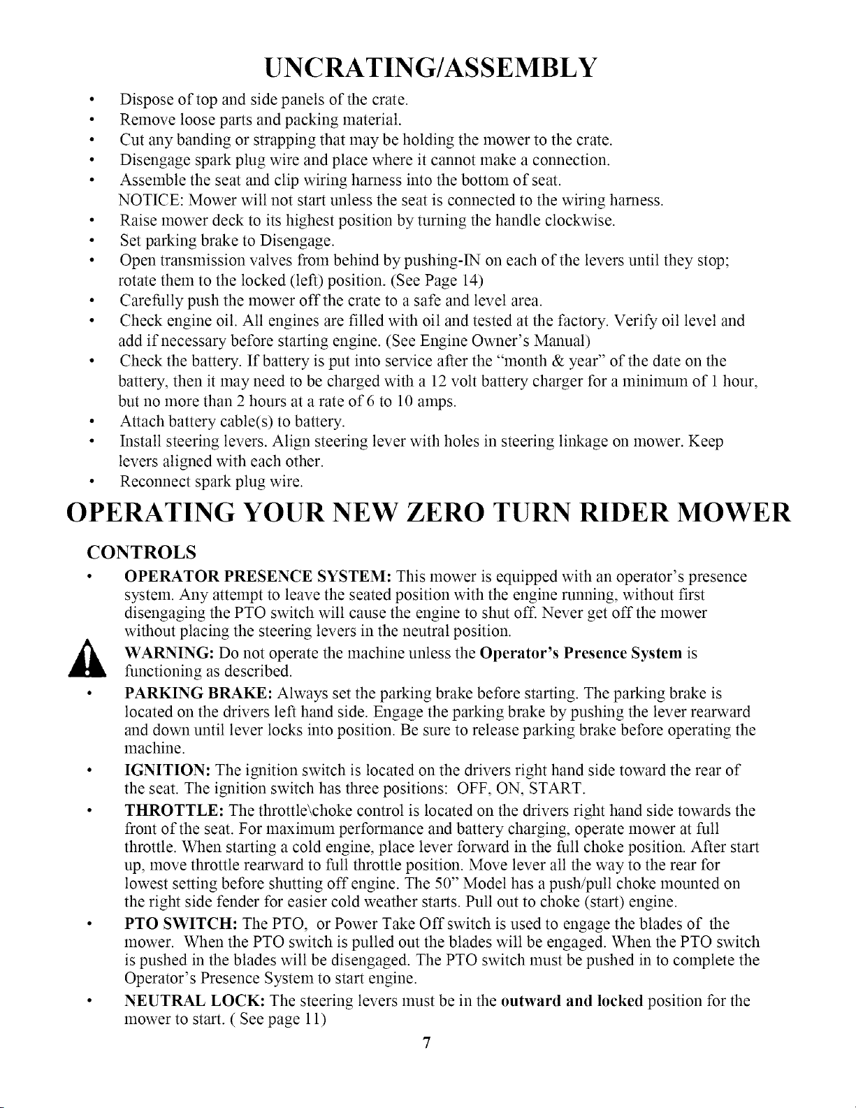
UNCRATING/ASSEMBLY
• Dispose of top and side panels of the crate.
• Remove loose parts and packing material.
• Cut any banding or strapping that may be holding the mower to the crate.
• Disengage spark plug wire and place where it cannot make a connection.
• Assemble the seat and clip wiring harness into the bottom of seat.
NOTICE: Mower will not start unless the seat is connected to the wiring harness.
• Raise mower deck to its highest position by turning the handle clockwise.
• Set parking brake to Disengage.
• Open transmission valves from behind by pushing-iN on each of the levers until they stop;
rotate them to the locked (left) position. (See Page 14)
• Carefully push the mower off the crate to a safe and level area.
• Check engine oil. All engines are filled with oil and tested at the factory. Verify oil level and
add if necessary before starting engine. (See Engine Owner's Manual)
• Check the battery. If battery is put into service after the "month & year" of the date on the
battery, then it may need to be charged with a 12 volt battery charger for a minimum of 1 hour,
but no more than 2 hours at a rate of 6 to 10 amps.
• Attach battery cable(s) to battery.
• Install steering levers. Align steering lever with holes in steering linkage on mower. Keep
levers aligned with each other.
• Reconnect spark plug wire.
OPERATING YOUR NEW ZERO TURN RIDER MOWER
CONTROLS
• OPERATOR PRESENCE SYSTEM: This mower is equipped with an operator's presence
system. Any attempt to leave the seated position with the engine running, without first
disengaging the PTO switch will cause the engine to shut off. Never get off the mower
without placing the steering levers in the neutral position.
WARNING: Do not operate the machine unless the Operator's Presence System is
functioning as described.
• PARKING BRAKE: Always set the parking brake before starting. The parking brake is
located on the drivers left hand side. Engage the parking brake by pushing the lever rearward
and down until lever locks into position. Be sure to release parking brake before operating the
machine.
• IGNITION: The ignition switch is located on the drivers right hand side toward the rear of
the seat. The ignition switch has three positions: OFF, ON, START.
• THROTTLE: The throttle\choke control is located on the drivers right hand side towards the
front of the seat. For maximum performance and battery charging, operate mower at full
throttle. When starting a cold engine, place lever forward in the full choke position. After start
up, move throttle rearward to full throttle position. Move lever all the way to the rear for
lowest setting before shutting off engine. The 50" Model has a push/pull choke mounted on
the right side fender for easier cold weather starts. Pull out to choke (start) engine.
• PTO SWITCH: The PTO, or Power Take Off switch is used to engage the blades of the
mower. When the PTO switch is pulled out the blades will be engaged. When the PTO switch
is pushed in the blades will be disengaged. The PTO switch must be pushed in to complete the
Operator's Presence System to start engine.
• NEUTRAL LOCK: The steering levers must be in the outward and locked position for the
mower to start. ( See page 11)
7
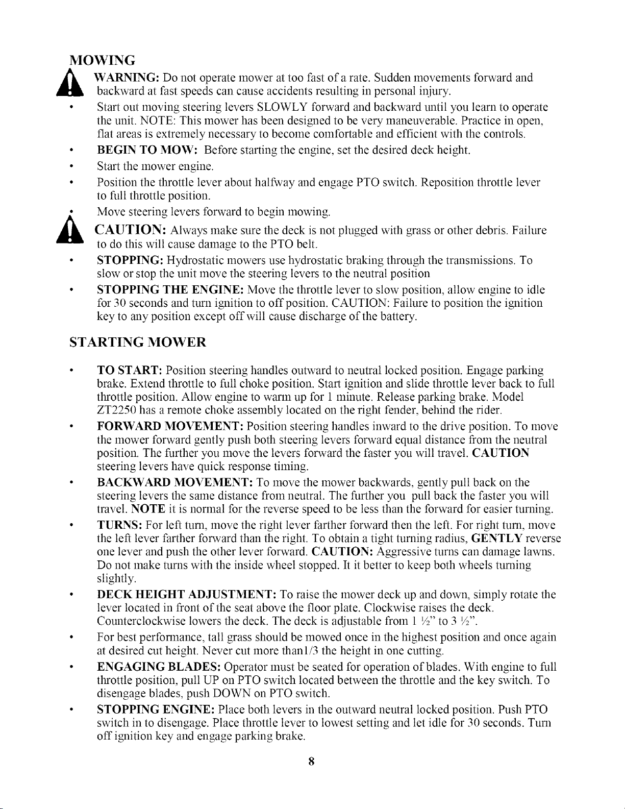
MOWING
WARNING: Do not operate mower at too fast of a rate. Sudden movements forward and
backward at fast speeds can cause accidents resulting in personal iniury.
• Start out moving steering levers SLOWLY forward and backward until you learn to operate
the unit. NOTE: This mower has been designed to be very maneuverable. Practice in open,
flat areas is extremely necessary to become comfortable and efficient with the controls.
• BEGIN TO MOW: Before starting the engine, set the desired deck height.
• Start the mower engine.
• Position the throttle lever about halfway and engage PTO switch. Reposition throttle lever
to full throttle position.
Move steering levers forward to begin mowing.
CAUTION: Always make sure the deck is not plugged with grass or other debris. Failure
to do this will cause damage to the PTO belt.
• STOPPING: Hydrostatic mowers use hydrostatic braking through the transmissions. To
slow or stop the unit move the steering levers to the neutral position
• STOPPING THE ENGINE: Move the throttle lever to slow position, allow engine to idle
for 30 seconds and turn ignition to off position. CAUTION: Failure to position the ignition
key to any position except off will cause discharge of the battery.
STARTING MOWER
TO START: Position steering handles outward to neutral locked position. Engage parking
brake. Extend throttle to full choke position. Start ignition and slide throttle lever back to full
throttle position. Allow engine to warm up for 1 minute. Release parking brake. Model
ZT2250 has a remote choke assembly located on the right fender, behind the rider.
FORWARD MOVEMENT: Position steering handles inward to the drive position. To move
the mower forward gently push both steering levers forward equal distance from the neutral
position. The further you move the levers forward the faster you will travel. CAUTION
steering levers have quick response timing.
BACKWARD MOVEMENT: To move the mower backwards, gently pull back on the
steering levers the same distance from neutral. The further you pull back the faster you will
travel. NOTE it is normal for the reverse speed to be less than the forward for easier turning.
TURNS: For left turn, move the right lever l_arther forward then the left. For right turn, move
the left lever farther forward than the right. To obtain a tight turning radius, GENTLY reverse
one lever and push the other lever forward. CAUTION: Aggressive turns can damage lawns.
Do not make turns with the inside wheel stopped. It it better to keep both wheels turning
slightly.
DECK HEIGHT ADJUSTMENT: To raise the mower deck up and down, simply rotate the
lever located in front of the seat above the floor plate. Clockwise raises the deck.
Counterclockwise lowers the deck. The deck is adjustable from 1 1/2"to 3 */2".
For best performance, tall grass should be mowed once in the highest position and once again
at desired cut height. Never cut more thanl/3 the height in one cutting.
ENGAGING BLADES: Operator must be seated for operation of blades. With engine to full
throttle position, pull UP on PTO switch located between the throttle and the key switch. To
disengage blades, push DOWN on PTO switch.
STOPPING ENGINE: Place both levers in the outward neutral locked position. Push PTO
switch in to disengage. Place throttle lever to lowest setting and let idle for 30 seconds. Turn
off ignition key and engage parking brake.
MAINTENANCE SCHEDULE
INSPECT BEFORE EACH USE
Loose fasteners: Be sure all fasteners are at proper torque. Especially guards and
blades.
Parking brake: If brake does not keep unit from rolling, brake must be adjusted or
repaired.
Tires: Always check and maintain proper tire pressure (See tire sidewall for
recommendation). Check for damage due to sharp rocks, objects or stumps.
Operator Presence System: The engine should not start unless the PTO switch is
disengaged and the control levers are locked in the neutral position. Any attempt to
leave the seated position with the PTO switch engaged will kill the engine.
Oil level: To prevent damage to engine, always check and maintain proper oil level.
Never operate engine with the oil level below the add mark on the dipstick. Be sure
to tighten the dipstick securely after inspection. Refer to engine manual for additional
information.
INSPECT EVERY 8 HOURS
Proper cleaning: Remove any build up of grass, dirt or debris with a brush or cloth
from engine, battery, deck and and transaxles. Do not use harsh chemicals or
abrasives. Keep all painted surfaces and wheels free ofoil and gasoline. Protect all
painted surfaces with an automotive wax. Do not spray unit with water or store
outdoors unprotected. Water can invade sealed bearings and reduce component life.
Do not spray water onto hydrostatic transmissions. This will
cause injection of water into the unit causing failure.
Air filter: The engine will not run properly with a dirty or damaged air filter. Check
filter before starting the engine. Check for buildup of dirt or debris. Replace if bent,
clogged, or damaged.
Oil level: To prevent damage to engine, always check and maintain proper oil level.
Never operate engine with the oil level below the add mark on the dipstick. Be sure to
tighten the dipstick securely after inspection.
INSPECT EVERY 25 HOURS
• Lubrication: Grease all pivot points with a high telnp grease.
• Battery, check and clean: Keep battery terminals clean and tight. Periodic charging
will extend its life. Clean terminals with a wire brush and coat with a petroleum jelly.
• Change engine oil and filter: Use only quality detergent oil. See engine manual for
instructions. Select viscosity grade according to your expected environmental
temperature.
• Blades: Best results will come from sharp blades. Replace if bent, damaged or worn.
• Engine air screen: Screen must be clean and free of debris for proper engine cooling.
Clean with a brush or cloth. Do not spray with pressurized water.
• Muffler: Inspect for damage or corrosion. Keep free of grass or debris to prevent fire.
INSPECT EVERY 100 HOURS
• Clean engine cooling fins: Clogged cooling fins can damage engine due to
overheating. Keep fins and external surfaces of the engine clean.
• Replace air filter: The engine will not run properly with a dirty or damaged air filter.
Check filter before starting the engine.Check for buildup of dirt or debris. Replace if
bent, clogged, or damaged. See engine manual for detailed instructions.
• Replace spark plugs: See engine manual for detailed instructions.
INSPECT EACH SEASON
• Belts:Check belts for wear and deterioration. See service and adjustments.
• Spark plug: See engine manual for detailed instructions.
• Replace in-line fuel filter: Replace every season.
INSPECT BEFORE STORAGE
• Change engine oil and filter: See engine manual for detailed instructions.
• Lubrication: Grease all pivot points with a high temp grease.
• Check battery: Keep battery terminals clean and tight. Periodic charging will extend
its life. Clean terminals with a wire brush and coat with a petroleum jelly.
• Loose fasteners: Be sure all fasteners are at proper torque, especially guards and
blades.
10
SERVICE / ADJUSTMENTS
,_ CAUTION: Before performing any service or adjustments do as follows:
1. Turn off PTO switch.
2. Position unit on smooth flat surface.
3. Place steering levers in outward, neutral-locked position.
4. Turn ignition key "OFF" and set parking brake.
5. Wait for all moving parts to stop and disconnect spark plug wire.
TRACKING
Adjustments to the unit may need to be made if the unit does not track in a straight line. The
primary reason for the unit not tracking straight is incorrect or unbalanced tire pressure.
Before making any adjustments first check and adjust the tire pressure. DO NOT EXCEED
MAXIMUM RECOMMENDED TIRE PRESSURE.
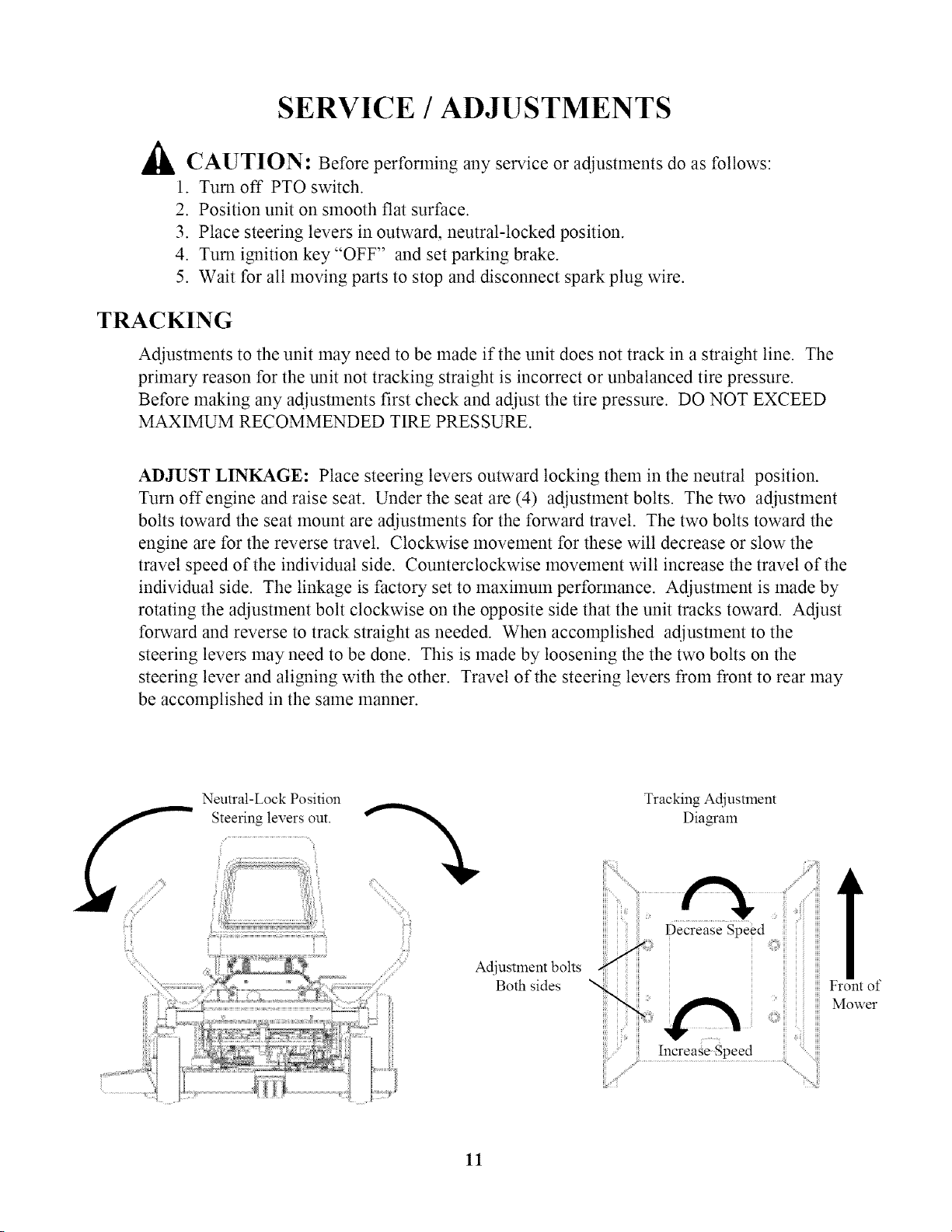
ADJUST LINKAGE: Place steering levers outward locking them in the neutral position.
Turn offengine and raise seat. Under the seat are (4) adjustment bolts. The two adjustment
bolts toward the seat mount are adjustments for the forward travel. The two bolts toward the
engine are for the reverse travel. Clockwise movement for these will decrease or slow the
travel speed of the individual side. Counterclockwise movement will increase the travel of the
individual side. The linkage is factory set to maximum performance. Adjustment is made by
rotating the adjustment bolt clockwise on the opposite side that the unit tracks toward. Adjust
forward and reverse to track straight as needed. When accomplished adjustment to the
steering levers may need to be done. This is made by loosening the the two bolts on the
steering lever and aligning with the other. Travel of the steering levers from front to rear may
be accomplished in the same manner.
iiii
Neutral-Lock Position
Steering levers out.
/
Tracking Adjustment
Dia_am
Adjustment bolts
ron Of ow
Both sides
11

REMOVING THE MOWER DECK
.
2.
3.
4.
.
6.
Turn off engine and engage parking brake.
Rotate cutting height lever counterclockwise to lowest cutting position.
Remove bolt from pickup point located at the front of the deck.
Remove cotter pins on rear hanger points and slide out stabilizer bars.Disconnect
tension spring bolt from tension bracket.
Remove belt from mower pulley and electric clutch.
Slide mower deck from under unit.
INSTALLING THE MOWER DECK
1. Be sure the cutting height lever is in the lowest position.
2. Position mower deck under unit.
3. Install belt around mower pulley and electric clutch.
4. Install stabilizer bars into rear hanger brackets through lift points and install cotter
pins. Be sure eye bolt is between bracket sides.
5. Install bolt in front hanger bracket passing through eyebolt in the same manner as
rear and tighten snug.
6. Reattach tension spring bolt and tighten.
NOTE: It is recolnmended to
remove the deck to sharpen the
blades.
f_ S_i
_i_i_ iiiiiil)_i
f_
//i ,'_'
Remove belt
12
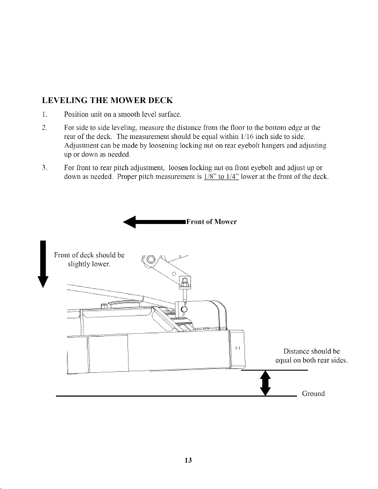
LEVELING THE MOWER DECK
1. Position unit on a smooth level surface.
.
.
For side to side leveling, measure the distance from the floor to the bottom edge at the
rear of the deck. The measurement should be equal within 1/16 inch side to side.
Adjustment can be made by loosening locking nut on rear eyebolt hangers and adjusting
up or down as needed.
For front to rear pitch adjustment, loosen locking nut on front eyebolt and adjust up or
down as needed. Proper pitch measurement is 1/8" to 1/4" lower at the front of the deck.
Front of Mower
-ml
Distance should be
equal on both rear sides.
Ground
13
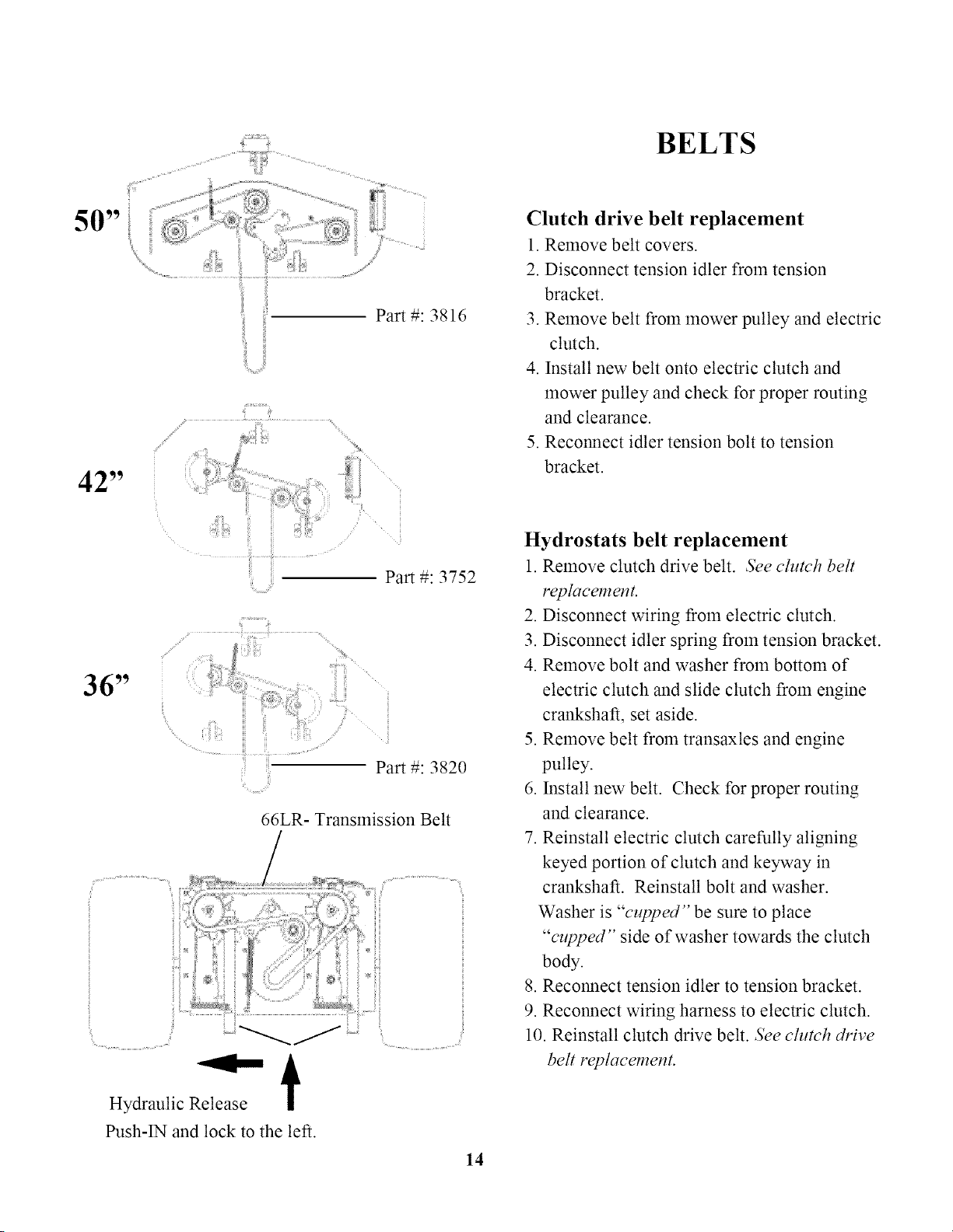
: BELTS
50"
Part #: 3816
42"
,/
Part #: 3752
36"
Part #: 3820
66LR- Transmission Belt
Hydraulic Release
€
Push-iN and lock to the left.
14
Clutch drive belt replacement
1. Remove belt covers.
2. Disconnect tension idler from tension
bracket.
3. Remove belt from mower pulley and electric
clutch.
4. Install new belt onto electric clutch and
mower pulley and check for proper routing
and clearance.
5. Reconnect idler tension bolt to tension
bracket.
Hydrostats belt replacement
1. Remove clutch drive belt. See clutch belt
replacement.
2. Disconnect wiring from electric clutch.
3. Disconnect idler spring from tension bracket.
4. Remove bolt and washer from bottom of
electric clutch and slide clutch from engine
crankshaft, set aside.
5. Remove belt from transaxles and engine
pulley.
6. Install new belt. Check for proper routing
and clearance.
7. Reinstall electric clutch carefully aligning
keyed portion of clutch and keyway in
crankshaft. Reinstall bolt and washer.
Washer is "cupped" be sure to place
"cupped" side of washer towards the clutch
body.
8. Reconnect tension idler to tension bracket.
9. Reconnect wiring harness to electric clutch.
10. Reinstall clutch drive belt. See clutch drive
belt replacement.
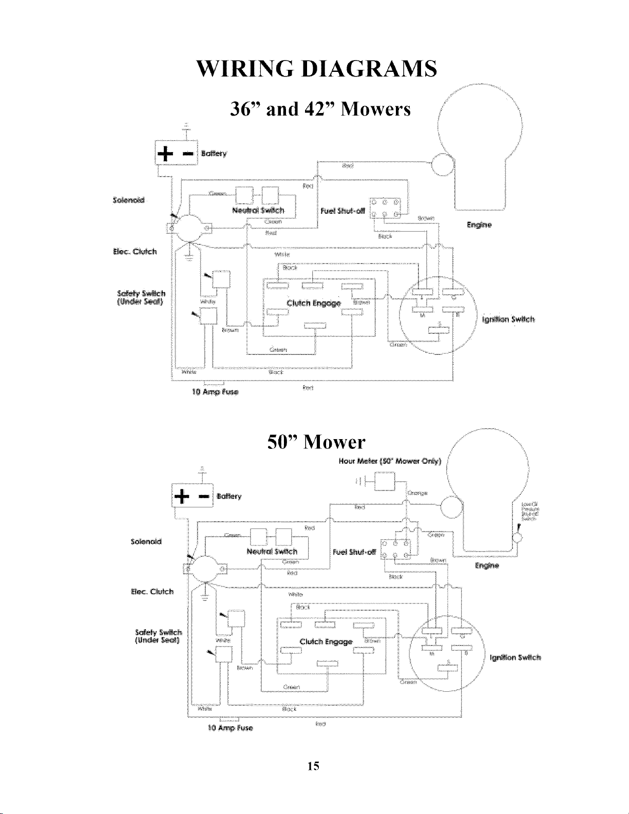
WIRING DIAGRAMS
36" and 42" Mowers
/
15
Item #
1
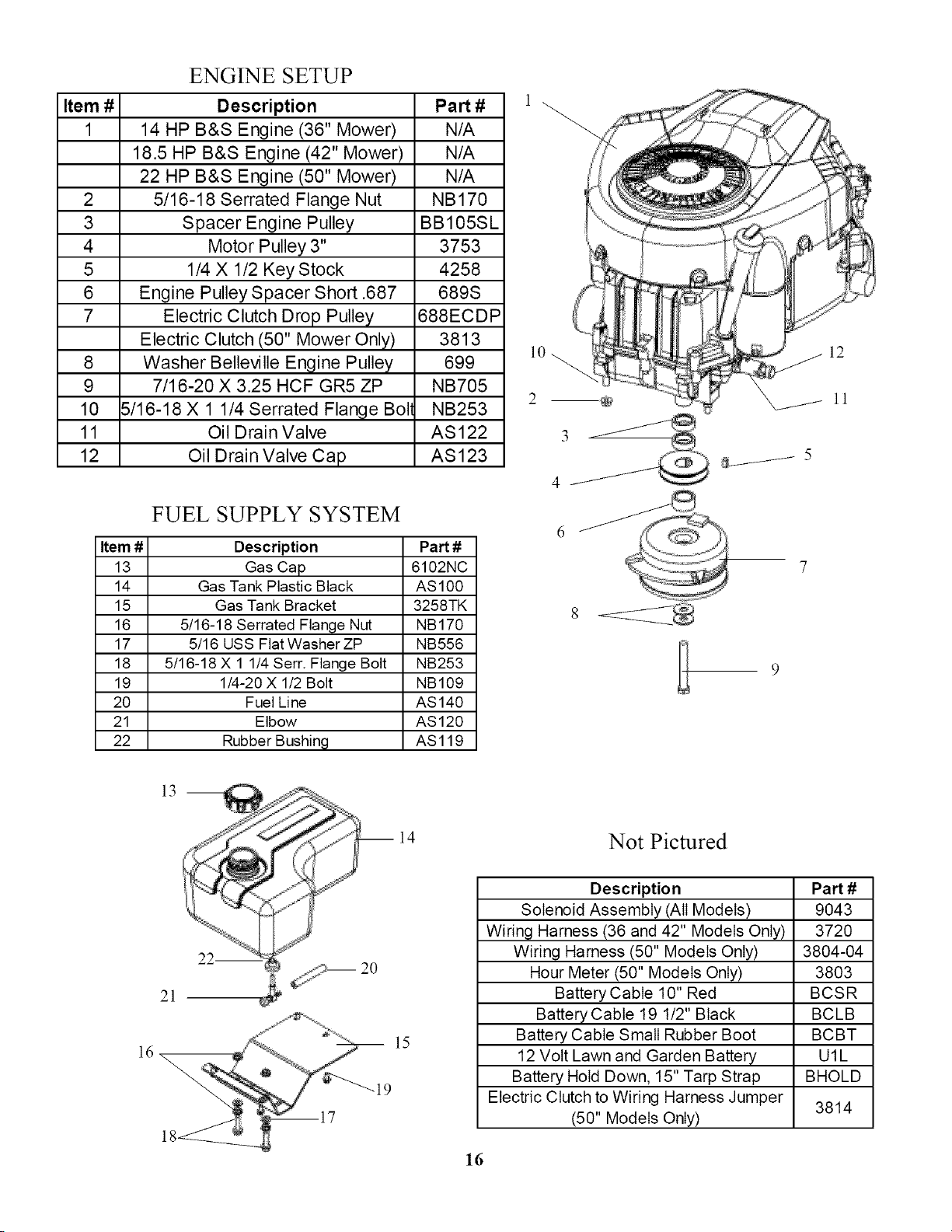
ENGINE SETUP
Description Part #
14 HP B&S Engine (36" Mower) N/A
18.5 HP B&S Engine (42" Mower) N/A
22 HP B&S Engine (50" Mower) N/A
2 5/16-18 Serrated Flange Nut NB170
3 Spacer Engine Pulley BB105SL
4 Motor Pulley 3" 3753
5 1/4 X 1/2 Key Stock 4258
6 Engine Pulley Spacer Short .687 689S
7 Electric Clutch Drop Pulley 688ECDP
Electric Clutch (50" Mower Only) 3813
8 Washer Belleville Engine Pulley 699
9 7/16-20 X 3.25 HCF GR5 ZP NB705
10 5/16-18 X 1 1/4 Serrated Flange Boll NB253
11 Oil Drain Valve AS122
12 Oil Drain Valve Cap AS123
FUEL SUPPLY SYSTEM
Item # Description
13 Gas Cap
14 Gas Tank Plastic Black
15 Gas Tank Bracket
16 5/16-18 Serrated Flange Nut
17 5/16 USS Flat Washer ZP
18 5/16-18 X 1 1/4 Serr. Flange Bolt
19 1/4-20 X 1/2 Bolt
20 Fuel Line
21 Elbow
22 Rubber Bushing
Part #
6102NC
AS100
3258TK
NB170
NB556
NB253
NB109
AS140
AS120
ASl19
J5
8
12
ll
13
21
ml4
15
19
Not Pictured
Description
Solenoid Assembly (All Models)
Wiring Harness (36 and 42" Models Only)
Wiring Harness (50" Models Only)
Hour Meter (50" Models Only)
Battery Cable 10" Red
Battery Cable 19 1/2" Black
Battery Cable Small Rubber Boot
12 Volt Lawn and Garden Battery
Battery Hold Down, 15" Tarp Strap
Electric Clutch to Wiring Harness Jumper
(50" Models Only)
PaN #
9043
3720
3804-04
3803
BCSR
BCLB
BCBT
U1L
BHOLD
3814
16
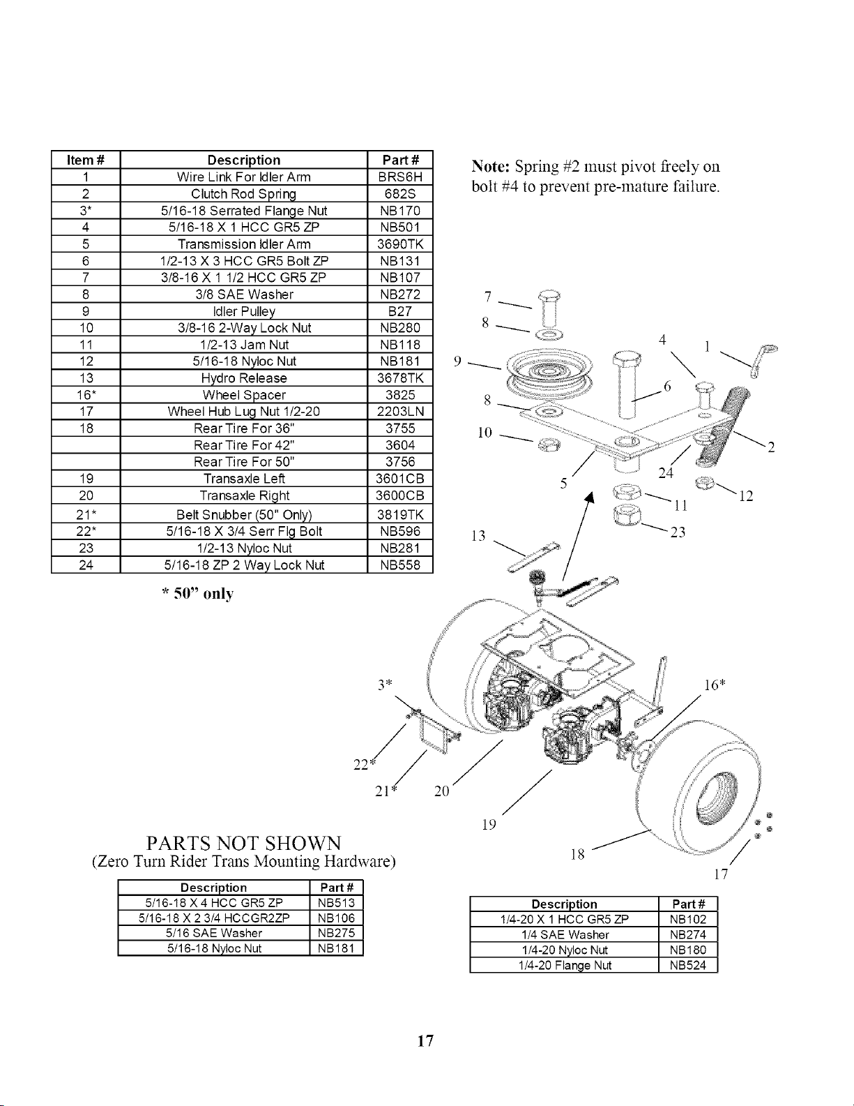
Item #
1
2
3*
4
5
6
7
8
9
10
11
12
13
16"
17
18
19
2O
21"
22*
23
24
Description
Wire Link For IdlerArm
Clutch Rod Spring
5/16-18 Serrated Flange Nut
5/16-18 X 1 HCC GR5ZP
Transmission IdlerArm
1/2-13 X 3 HCC GR5 Bolt ZP
3/8-16 X 1 1/2 HCC GR5ZP
3/8 SAE Washer
Idler Pulley
3/8-16 2-Way Lock Nut
1/2-13 Jam Nut
5/16-18 Nyloc Nut
Hydro Release
Wheel Spacer
Wheel Hub Lug Nut 1/2-20
Rear Tire For 36"
Rear Tire For 42"
Rear Tire For 50"
Transaxle Left
Transaxle Right
Belt Snubber (50" Only)
5/16-18 X 3/4 Serr FIg Bolt
1/2-13 Nyloc Nut
5/16-18 ZP 2 Way Lock Nut
Part#
BRS6H
682S
NB170
NB501
3690TK
NB131
NB107
NB272
B27
NB280
NBl18
NB181
3678TK
3825
2203LN
3755
3604
3756
3601CB
3600CB
3819TK
NB596
NB281
NB558
* 50" only
Note: Spring #2 must pivot freely on
bolt #4 to prevent pre-mamre failure.
8_
9_
l0
24
13
PARTS NOT SHOWN
(Zero Turn Rider Trans Mounting Hardware)
Description Part #
5/16-18 X 4 HCC GR5 ZP NB513
5/16-18X 2 3/4HCCGR2ZP NB106
5/16 SAE Washer NB275
5/16-18NylocNut NB181
18
Description Part #
1/4-20 X 1 HCC GR5 ZP NB102
1/4 SAE Washer NB274
1/4-20 Nyloc Nut NB180
1/4-20 Flange Nut NB524
17
17
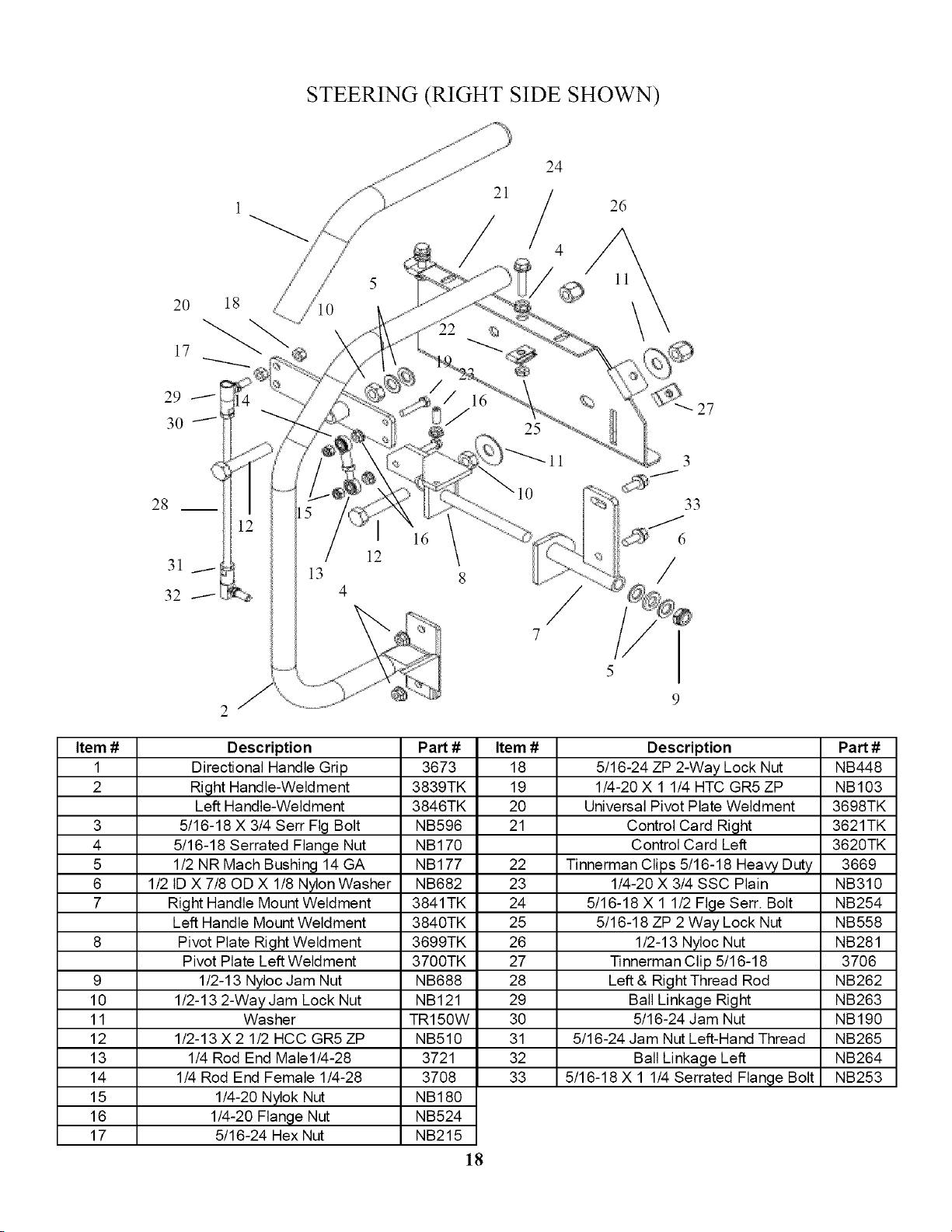
STEERING (RIGHT SIDE SHOWN)
2O
17
18
21
24
/4
26
Item #
1
2
3
4
5
6
7
9
10
11
12
13
14
15
16
17
28
3
33
6
/
Description
Directional Handle Grip
Right Handle-Weldment
Left Handle-Weldment
5/16-18 X 3/4 Serr Fig Bolt
5/16-18 Serrated Flange Nut
1/2 NR Mach Bushing 14 GA
1/2 ID X 7/80D X 1/8 N_on Washer
Right Handle Mount Weldment
Left Handle Mount Weldment
Pivot Plate Right Weldment
Pivot Plate Left Weldment
1/2-13 Nyloc Jam Nut
1/2-13 2-Way Jam Lock Nut
Washer
1/2-13 X 2 1/2 HCC GR5ZP
1/4 Rod End Male1/4-28
1/4 Rod End Female 1/4-28
1/4-20 Nylok Nut
1/4-20 Flange Nut
5/16-24 Hex Nut
Part #
3673
3839TK
3846TK
NB596
NB170
NB177
NB682
3841 TK
3840TK
3699TK
3700TK
NB688
NB121
TR150W
NB510
3721
3708
NB180
NB524
NB215
18
Item #
18
19
2O
21
22
23
24
25
26
27
28
29
30
31
32
33
Description
5/16-24 ZP 2-Way Lock Nut
1/4-20 X 1 1/4 HTC GR5 ZP
Universal Pivot Plate Weldment
Control Card Right
Control Card Left
Tinnerman Clips 5/16-18 Heavy Duty
1/4-20 X 3/4 SSC Plain
5/16-18 X 1 1/2 Flge Serr. Bolt
5/16-18 ZP 2 Way Lock Nut
1/2-13 Nyloc Nut
Tinnerman Clip 5/16-18
Left & Right Thread Rod
Ball Linkage Right
5/16-24 Jam Nut
5/16-24 Jam Nut Left-Hand Thread
Ball Linkage Left
5/16-18 X 1 1/4 Serrated Flange Bolt
Part #
NB448
NB103
3698TK
3621TK
3620TK
3669
NB310
NB254
NB558
NB281
3706
NB262
NB263
NB190
NB265
NB264
NB253
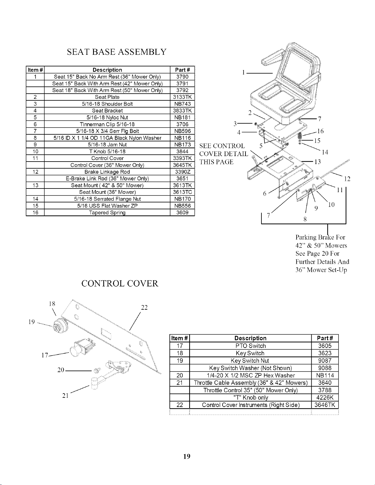
SEAT BASE ASSEMBLY
Item #
I
2
3
4
5
6
7
8
9
10
11
12
13
14
15
16
Description Part #
Seat 15" Back No Arm Rest (36" Mower Only) 3790
Seat 15" Back With Arm Rest (42" Mower Only) 3791
Seat 18" Back With Arm Rest (50" Mower Only) 3792
Seat Plate 3133TK
5/16-18 Shoulder Bolt NB743
Seat Bracket 3833TK
5/16-18 Nyloc Nut NB181
Tinnerman Clip 5/16-18 3706
5/16-18 X 3/4 Serr Fig Bolt NB596
5/16 ID X 1 1/40D 11GA Black N_on Washer NBl16
5/16-18 Jam Nut NB173
T Knob 5/16-18 3844
Control Cover 3393TK
Control Cover (36" Mower Only) 3645TK
Brake Linkage Rod 3390Z
E-Brake Link Rod (36" Mower Only) 3651
Seat Mount ( 42" & 50" Mower) 3613TK
Seat Mount (36" Mower) 3613TC
5116-18 Serrated Flange Nut NB170
5116 USS Flat Washer ZP NB556
Tapered Spring 3609
CONTROLCOVER
SEE CONTROL 5
COVER DETAIL
THIS PAGE
12
ll
l0
9
8
Parking Bra_e For
42" & 50" Mowers
See Page 20 For
Further Details And
36" Mower Set-Up
2O
21
i. i!¸
Item #
17
18
19
2O
21
22
Description
PTO Switch
Key Switch
Key Switch Nut
Key Switch Washer (Not Shown)
1/4-20 X 1/2 MSC ZP HexWasher
Throttle Cable Assembly (36" & 42" Mowers)
Throttle Control 35" (50" Mower Only)
"T" Knob only
Control Cover Instruments (Right Side)
Pa_#
3605
3623
9087
9088
NBl14
3640
3788
4226K
3646TK
19
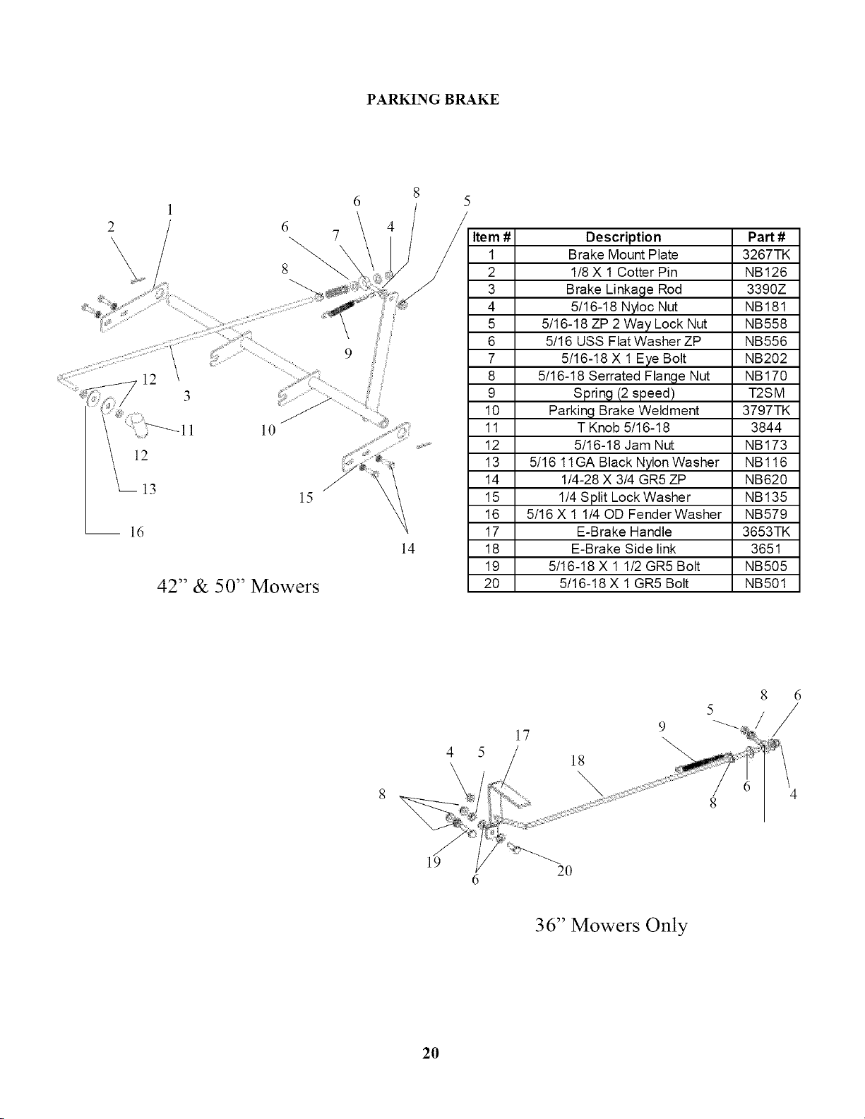
PARKING BRAKE
12
13
ld
l l0
15
42" & 50" Mowers
9
j! /
14
Item #
1
2
3
4
5
6
7
8
9
10
11
12
13
14
15
16
17
18
19
2O
Description
Brake Mount Plate
1/8 X 1 Cotter Pin
Brake Linkage Rod
5/16-18 Nyloc Nut
5/16-18 ZP 2 Way Lock Nut
5/16 USS Flat Washer ZP
5/16-18 X 1 Eye Bolt
5/16-18 Serrated Flange Nut
Spring (2 speed)
Parking Brake Weldment
Part #
3267TK
NB126
3390Z
NB181
NB558
NB556
NB202
NB170
T2SM
3797TK
T Knob 5/16-18 3844
5/16-18 Jam Nut NB173
5/16 11GA Black Nylon Washer NBl16
1/4-28 X 3/4 GR5 ZP NB620
1/4 Split Lock Washer NB135
5/16 X 1 1/40D Fender Washer NB579
E-Brake Handle 3653TK
E-Brake Side link 3651
5/16-18 X 1 1/2 GR5 Bolt NB505
5/16-18 X 1 GR5 Bolt NB501
17
18
\
9
19
20
6
36" Mowers Only
2O
ll
\
3
\
10
2
\
@
15
7
\
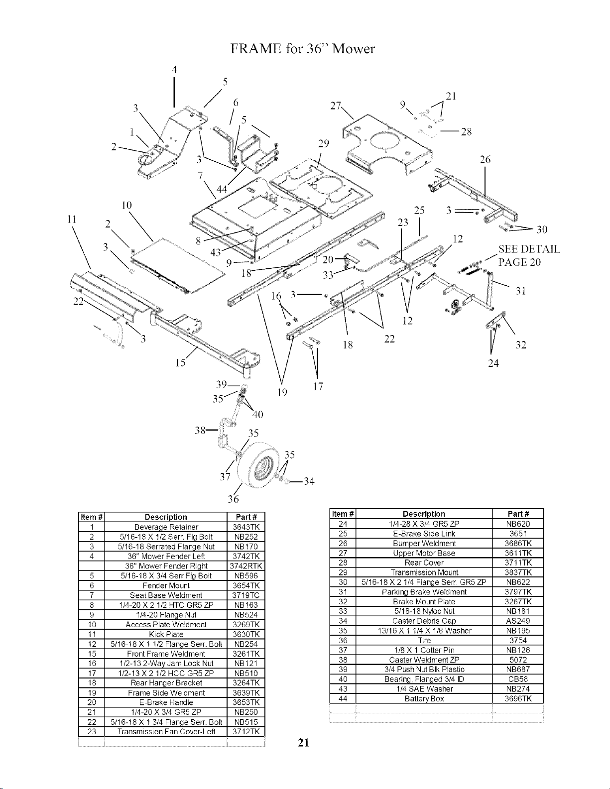
FRAME for 36" Mower
5
6
/5
23
9
33
18
39-- 17
19
25
12
12
22
SEE DETAIL
31
32
24
36
Item # Description Part #
1 Beverage Retainer 3643TK
2 5/16-18 X 1/2 Serr. Fig Bolt NB252
3 5/16-18 Serrated Flange Nut NB170
4 36" Mower Fender Left 3742TK
36" Mower Fender Right 3742RTK
5 5/16-18 X 3/4 Serr Fig Bolt NB596
6 Fender Mount 3654TK
7 Seat Base Weldment 3719TC
8 1/4-20 X 2 1/2 HTC GR5 ZP NB163
9 1/4-20 Flange Nut NB524
10 Access Plate Weldment 3269TK
11 Kick Plate 3630TK
12 5/16-18 X 1 1/2 Flange Serr. Bolt NB254
15 Front Frame Weldment 3261TK
16 1/2-13 2-Way Jam Lock Nut NB121
17 1/2-13 X 2 1/2 HCC GR5 ZP NB510
18 Rear Hanger Bracket 3264TK
19 Frame Side Weldment 3639TK
20 E-Brake Handle 3653TK
21 1/4-20 X 3/4 GR5 ZP NB250
22 5/16-18 X 1 3/4 Flange Serr. Bolt NB515
23 Transmission Fan Cover-Left 3712TK
Item #
24
25
26
27
28
29
30
31
32
33
34
35
36
37
38
39
40
43
44
Description
1/4-28 X 3/4 GR5 ZP
E-Brake Side Link
Bumper Weldment
Upper Motor Base
Rear Cover
Transmission Mount
5/16-18 X 2 1/4 Flange Serr. GR5 ZP
Parking Brake Weldment
Brake Mount Plate
5/16-18 Nyioc Nut
Caster Debris Cap
13/16 X 1 1/4X 1/8 Washer
Tire
1/8 X 1 Cotter Pin
Caster Weldment ZP
3/4 Push Nut BIk Plastic
Bearing, Flanged 3/4 ID
1/4 SAE Washer
Battery Box
Part #
NB620
3651
3686TK
3611TK
3711TK
3837TK
NB622
3797TK
3267TK
NB181
AS249
NB195
3754
NB126
5072
NB687
CB58
NB274
3696TK
21
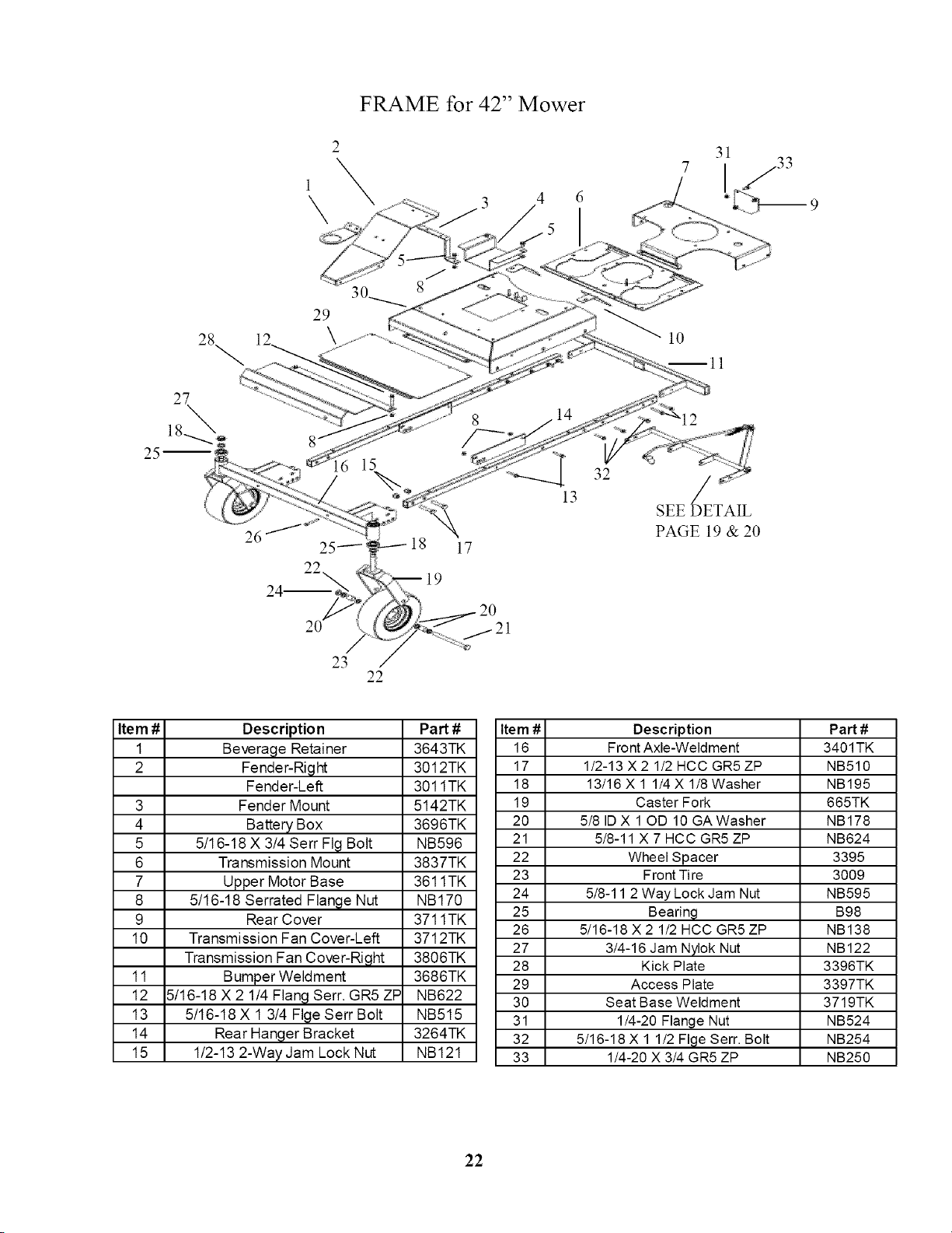
FRAME for 42" Mower
2
\\
4
.5
31
[j33
26
29
10
32
13 /
SEE DETAIL
PAGE 19 & 20
22
Item #
1
2
Description Part #
Beverage Retainer 3643TK
Fender-Right 3012TK
Fender-Left 3011TK
3 Fender Mount 5142TK
4 Battery Box 3696TK
5 5/16-18 X 3/4 Serr Fig Bolt NB596
6 Transmission Mount 3837TK
7 Upper Motor Base 3611TK
8 5/16-18 Serrated Flange Nut NB170
9 Rear Cover 3711TK
10 Transmission Fan Cover-Left 3712TK
Transmission Fan Cover-Right 3806TK
11 Bumper Weldment 3686TK
12 5/16-18 X 2 1/4 Flan9 Serr. GR5 ZP NB622
13 5/16-18 X 1 3/4 Flge Serr Bolt NB515
14 Rear Hanger Bracket 3264TK
15 1/2-13 2-Way Jam Lock Nut NB121
Item #
16
17
18
19
2O
21
22
23
24
25
26
27
28
29
3O
31
32
33
Description
Front Axle-Weldment
1/2-13 X 2 1/2 HCC GR5 ZP
13/16 X 1 1/4 X 1/8 Washer
Caster Fork
5/8 ID X 10D 10 GA Washer
5/8-11 X 7 HCC GR5 ZP
Wheel Spacer
Front Tire
5/8-11 2 Way Lock Jam Nut
Bearing
5/16-18 X 2 1/2 HCC GR5 ZP
3/4-16 Jam Nylok Nut
Kick Plate
Access Plate
Seat Base Weldment
1/4-20 Flange Nut
5/16-18 X 1 1/2 Flge Serr. Bolt
1/4-20 X 3/4 GR5 ZP
Part#
3401TK
NB510
NB195
665TK
NB178
NB624
3395
3009
NB595
B98
NB138
NB122
3396TK
3397TK
3719TK
NB524
NB254
NB250
22
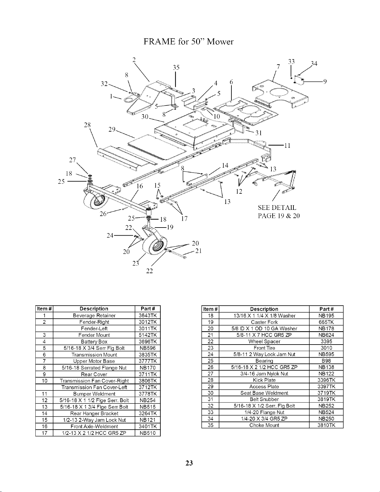
FRAME for 50" Mower
35
28
15
18
17
13
,2 /
13
SEE DETAIL
PAGE 19 & 20
24--.
20
23
22
2O
Item # Description Part #
1 Beverage Retainer 3643TK
2 Fender-Right 3012TK
Fender-Left 3011TK
3 Fender Mount 5142TK
4 Battery Box 3696TK
5 5/16-18 X 3/4 Serf Fig Bolt NB596
6 Transmission Mount 3835TK
7 Upper Motor Base 3777TK
8 5/16-18 Serrated Flange Nut NB170
9 Rear Cover 3711TK
10 Transmission Fan Cover-Right 3806TK
Transmission Fan Cover-Left 3712TK
11 Bumper Weldment 3778TK
12 5/16-18 X 1 1/2 FIge Serr. Bolt NB254
13 5/16-18 X 1 3/4 FIge Serr Bolt NB515
14 Rear Hanger Bracket 3264TK
15 1/2-13 2-Way Jam Lock Nut NB121
16 Front Axle-Weldment 3401TK
17 1/2-13 X 2 1/2 HCC GR5 ZP NB510
Item
18
19
2O
21
22
23
24
25
26
27
28
29
3O
31
32
33
34
35
Description
13/16 X 1 1/4X 1/8 Washer
Caster Fork
5/8 ID X 10D 10 GA Washer
5/8-11 X 7 HCC GR5 ZP
Wheel Spacer
Front Tire
5/8-11 2 Way Lock Jam Nut
Beadng
5/16-18 X 2 1/2 HCC GR5 ZP
3/4-16 Jam Nylok Nut
Kick Plate
Access Plate
Seat Base Weldment
Belt Snubber
5/16-18 X 1/2 Serr. Fig Bolt
1/4-20 Flange Nut
1/4-20 X 3/4 GR5 ZP
Choke Mount
Part#
NB195
665TK
NB178
NB624
3395
3010
NB595
B98
NB138
NB122
3396TK
3397TK
3719TK
3819TK
NB252
NB524
NB250
3810TK
23
12
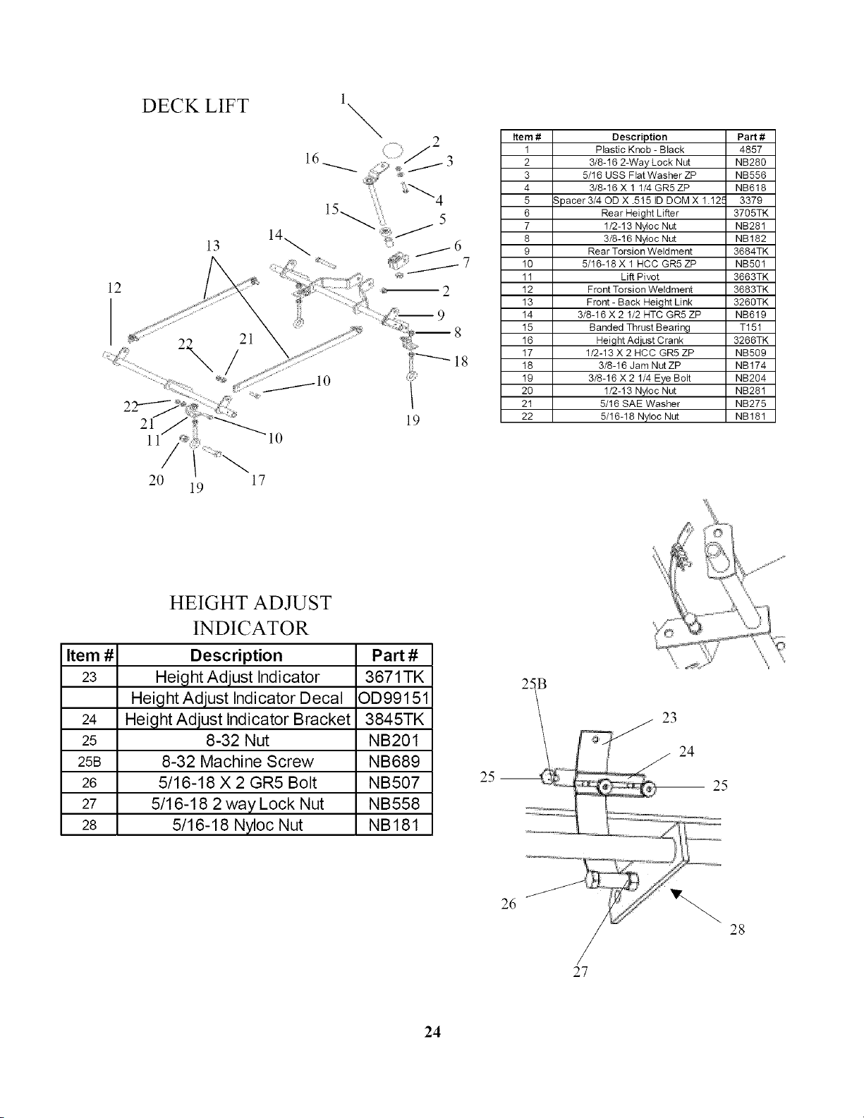
DECK LIFT
13
21
l
\
19
Item # Description Part #
1 Plastic Knob - Black 4857
2 3/8-16 2-Way Lock Nut NB280
3 5/18 USS Fiat Washer ZP NB558
4 3/8-16 X 1 1/4 GR5 ZP NB618
5 Spacer 3/40D X .515 tD DOM X 1.125 3379
6 Rear Height Lifter 3705TK
7 1/2-13 Nyloc Nut NB281
8 3/8-16 N_oc Nut NB182
9 Rear Torsion Weldment 3684TK
10 5/16-18 X 1 HCC GR5 ZP NB501
11 Lift Pivot 3663TK
12 Front Torsion Weldment 3683TK
13 Front- Back Height Link 3260TK
14 3/8-16 X 2 I/2 HTC GR5 ZP NB619
15 Banded Thrust Bearing T151
16 Height Adjust Crank 3266TK
17 1/2-13 X 2 HCC GR5 ZP NB509
18 3/8-16 Jam NutZP NB174
19 3/8-16 X 2 1/4 Eye Bolt NB204
20 1/2-13 N_oc Nut NB281
21 5/16 SAE Washer NB275
22 5/16-18 Nyloc Nut NB 181
20 17
19
Item # Part #
23 3671TK
OD99151
24 3845TK
25 NB201
25B NB689
26 NB507
27 NB558
28 NB181
HEIGHT ADJUST
INDICATOR
Description
Height Adjust Indicator
Height Adjust Indicator Decal
Height Adjust Indicator Bracket
8-32 Nut
8-32 Machine Screw
5/16-18 X 2 GR5 Bolt
5/16-18 2 way Lock Nut
5/16-18 Nyloc Nut
2_ / 2324
__,_, 25
26 28
27
24
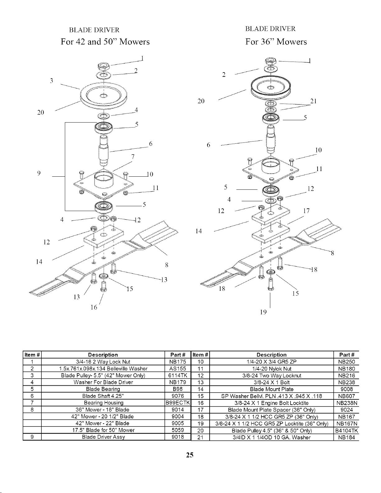
BLADEDRIVER
For 42 and 50" Mowers
BLADE DRIVER
For 36" Mowers
2O
12
14
/
13
ld
d
7
_o
ll
/
8
_13
2O
14
2
5
4
12
19
11
12
17
15
Item #
1
2
3
4
5
6
7
8
Description
3/4-16 2 Way Lock Nut
1.5x.761 x.098x.134 Belleville Washer
Blade Pulley- 5.5" (42" Mower Only)
Washer For Blade Driver
Blade Bearing
Blade Shaft 4.25"
Bearing Housing
36" Mower- 18" Blade
42" Mower- 20 1/2" Blade
42" Mower - 22" Blade
17.5" Blade for 50" Mower
Blade Driver Assy
Pa_ #
NB175
AS155
6114TK
NB179
B98
9076
B99ECTK
9014
9004
9005
5059
9018
Item #
10
11
12
13
14
15
16
17
18
19
20
21
Description
1/4-20 X 3/4 GR5 ZP
1/4-20 Nylok Nut
3/8-24 Two Way Locknut
3/8-24 X 1 Bolt
Blade Mount Plate
SP Washer Bellvl. PLN .413 X .945 X .118
3/8-24 X 1 Engine Bolt Locktite
Blade Mount Plate Spacer (36" Only)
3/8-24 X 1 1/2 HCC GR5 ZP (36" Only)
3/8-24 X 1 1/2 HCC GR5 ZP Locktite (36" Only)
Blade Pulley 4.5" (36" & 50" Only)
3/41D X 1 1/4OD 10 GA. Washer
Part#
NB250
NB180
NB216
NB238
9008
NB607
NB238N
9024
NB167
NB167N
B4104TK
NB184
25
3
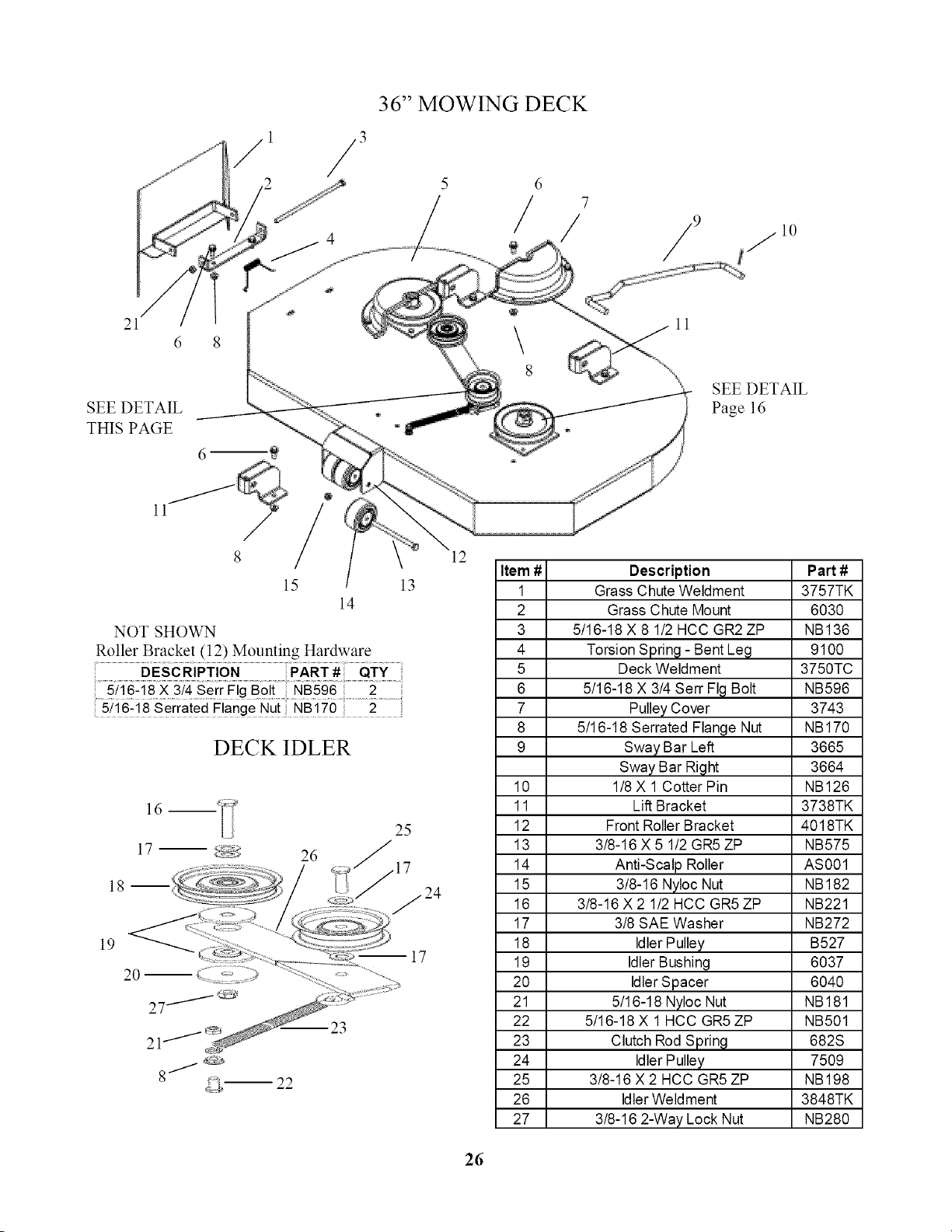
36" MOWING DECK
5 6
7
/
21
6 8
SEE DETAIL
THIS PAGE
15
14
NOT SHOWN
Roller Bracket (12) Mounting Hardware
DESCRIPTION PART # QTY
5/16-18 X 3/4 SerrFIg Bolt NB596 .......2..........
5/16-18 Serrated Flange Nut NB170 2
13
DECKIDLER
12
Item #
1
2
3
4
5
6
7
8
9
10
11
12
13
14
15
16
17
18
19
2O
21
22
23
24
25
26
27
16m
J
8 _
m 22
25
10
11
SEE DETAIL
Page 16
Description
Grass Chute Weldment
Grass Chute Mount
5/16-18 X 8 1/2 HCC GR2ZP
Torsion Spring - Bent Leg
Deck Weldment
5/16-18 X 3/4 Serr Fig Bolt
Pulley Cover
5/16-18 Serrated Flange Nut
Sway Bar Left
Sway Bar Right
1/8X 1Cotter Pin
Lift Bracket
Front Roller Bracket
3/8-16 X 5 1/2 GR5 ZP
Anti-Scalp Roller
3/8-16 Nyloc Nut
3/8-16 X 2 1/2 HCC GR5 ZP
3/8 SAE Washer
Idler Pulley
IdlerBushing
IdlerSpacer
5/16-18 Nyloc Nut
5/16-18 X 1HCC GR5ZP
Clutch Rod Spring
Idler Pulley
3/8-16 X 2 HCC GR5 ZP
IdlerWeldment
3/8-16 2-Way Lock Nut
Part#
3757TK
6030
NB136
9100
3750TC
NB596
3743
NB170
3665
3664
NB126
3738TK
4018TK
NB575
AS001
NB182
NB221
NB272
B527
6037
6040
NB181
NB501
682S
7509
NB198
3848TK
NB280
26
ll
15
14"
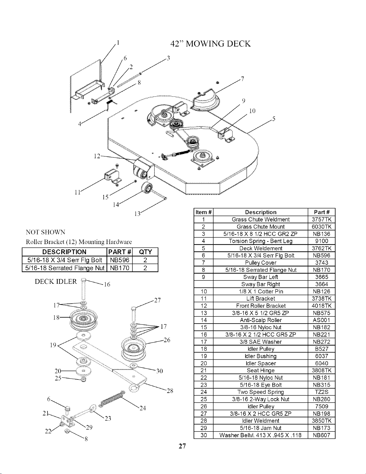
NOT SHOWN
Roller Bracket (12) Mounting Hardware
DESCRIPTION PART #
5/16-18 X 3/4 Serr Fig Bolt NB596
5/16-18 Serrated Flange Nut NB170
DECK IDLER
23
29
42" MOWING DECK
_3
@
9
l0
QTY
2
2
28
24
27
Item #
1
2
3
4
5
6
7
8
9
10
11
12
13
14
15
16
17
18
19
20
21
22
23
24
25
26
27
28
29
30
Description
Grass Chute Weldment
Grass Chute Mount
5/16-18 X 8 1/2 HCC GR2 ZP
Torsion Spring - Bent Leg
Deck Weldement
5/16-18 X 3/4 Serr Fig Bolt
Pulley Cover
5/16-18 Serrated Flange Nut
Sway Bar Left
Sway Bar Right
1!8X 1Cotter Pin
Lift Bracket
Front Roller Bracket
3/8-16 X 5 1!2 GR5 ZP
Anti-Scalp Roller
3!8-16 Nyloc Nut
3!8-16 X 2 1/2 HCC GR5 ZP
3!8 SAE Washer
Idler Pulley
Idler Bushing
Idler Spacer
Seat Hinge
5!16-18 Nyloc Nut
5!16-18 Eye Bolt
Two Speed Spring
3!8-16 2-Way Lock Nut
Idler Pulley
3!8-16 X 2 HCC GR5 ZP
IdlerWeldment
5!16-18 Jam Nut
Washer Bellvl. 413 X .945 X .118
Pad #
3757TK
6030TK
NB136
9100
3762TK
NB596
3743
NB170
3665
3664
NB126
3738TK
4018TK
NB575
AS001
NB182
NB221
NB272
B527
6037
6040
3808TK
NB181
NB315
TZ2S
NB280
7509
NB198
3850TK
NB173
NB607
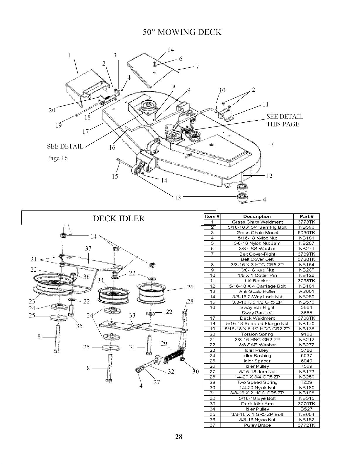
50" MOWING DECK
14
6
20
1!
10
SEE DETAIL
THIS PAGE
Page 16
ld
15
12
21
22
/
23 "_ 22
DECK IDLER
14
37
35
32
27
4
26
:8
3O
_d# Description
Grass Chute Weldment
5/16-16 X 3/4 Serr Fig Bolt
3 Grass Chute Mount
4 5/16-18 Nyloc Nut
5 3/8-16 Nylok Nut Jam
6 3/8 USS Washer
7 Belt Cover-Right
Belt Cover-Left
8 3/8-16 X 3 HTC GR5 ZP
9 3/8-16 Kep Nut
10 118 X 1 Cotter Pin
11 Lift Bracket
12 5/16-18 X 4 Carriage Bolt
13 Anti-Scalp Roller
14 3/8-16 2-Way Lock Nut
15 3/8-16 X 5 1/2 GR5 ZP
16 Sway Bar-Right
Sway Bar-Left
17 Deck Weldment
18 5/16-18 Serrated Flange Nut
19 5/16-18 X 8 1/2 HCC GR2 ZP
20 Torsion Spring
21 3/8-16 HNC GR2 ZP
22 3/8 SAE Washer
23 Idler Pulley
24 Idler Bushing
25 Idler Spacer
26 Idler Pulley
27 5/16-18 Jam Nut
28 1/4-20 X 3/4 GR5 ZP
29 Two Speed Spring
30 1/4-20 Nylok Nut
31 3/8-16 X 2 HCC GR5 ZP
32 5/16-18 Eye Bolt
33 Deck Idler Arm
34 Idler Pulley
35 3/8-16 X 1 GR5 ZP Bolt
36 3/8-16 Nyloc Nut
37 Pulley Brace
Pa_ #
3773TK
NB596
6030TK
NB181
NB207
NB271
3769TK
3768TK
NB164
NB205
NB126
3738TK
NB101
AS001
NB280
NB575
3664
3665
3766TK
NB170
NB136
9100
NB212
NB272
3786
6037
6040
7509
NB173
NB250
TZ2S
NB180
NB198
NB315
3770TK
B527
NB604
NB182
3772TK
28

TROUBLESHOOTING
SYMPTOM CAUSE CORRECTION
ENGINE HARD
TO START
ENGINE WILL
NOT START
OR LOSS OF
POWER
UNIT DOES
NOT TRACK
STRAIGHT
i.
2.
3.
4.
5.
WEAK OR DEAD BATTERY
AIR FILTER DIRTY
BAD SPARK PLUG
FUEL FILTER DIRTY
STALE OR CONTAMINATED FUEL
CARBURATOR OUT OF AD,RJSTMENT
2.
3.
4.
5.
6.
7.
8.
9.
i0.
i1.
12.
STEERING LEVERS NOT IN NEUTRAL
LOCKED POSITION
PTO SWITCH IS ENGAGED
THROTTLE NOT SET PROPERLY OR
NOT PROPERLY "CHOKED"
ENGINE FLOODED
DIRTY FUEL FILTER
DIRTY AIR FILTER
CONTAMINATED FUEL
BLOWN FUSE
BAD SPARK PLUG OR LOOSE PLUG
WIRE
DIRTY ENGINE AIR SCREENS
WEAK OR DEAD BATTERY
CARBURATOR OUT OF AD,RJSTMENT
13.
14.
15.
16.
17.
OUT OF FUEL
CORRODED BATTERY TERMINALS
LOOSE OR DAMAGED WIRING
LOW OR DIRTY OIL
DEBRIS BUILT-UP UNDER DECK
i.
2.
IMPROPER AIR PRESSURE
TRACKING ADJUSTMENTS OUT OF
ADJUSTMENT
i.
2.
3.
4.
5.
REPLACE OR RECHARGE
CLEAN OR REPLACE
REPLACE SPARK PLUG
REPLACE FUEL FILTER
DRAIN AND REPLACE WITH
FRESH FUEL
CONTACT NEAREST
BRIGGS&STRATTON SERVICE
REPRESENTATIVE
i. MOVE LEVERS INTO POSITION
2.
3.
5.
6.
7.
8.
9.
i0.
i1.
12.
13.
14.
15.
16.
17.
PUSH PTO SWITCH IN
SEE START UP IN OPERATION
SECTION
WAIT SEVERAL MINUTES
BEFORE STARTING
REPLACE WITH NEW FILTER
REPLACE OR CLEAN
DRAIN AND REPLACE WITH
FRESH FUEL
REPLACE FUSE
REPLACE PLUG AND TIGHTEN
PLUG WIRE
CLEAN ENGINE AIR SCREENS
REPLACE OR RECHARGE
CONTACT NEAREST
BRIGGS&STRATTON SERVICE
REPRESENTATIVE
REPLACE WITH FRESH FUEL
CLEAN" TERMINALS
CONTACT SWISHER SERVICE
REPRESENTATIVE
ADD OIL / RECHECK LEVEL
CHANGE OIL
CLEAN" UNDERSIDE OF MOWER
i.
2.
CHECK AND ADJUST TIRE
PRESSURE
SEE TRACKING AD,RJSTMENT IN
SERVICE SECTION
29

SUGGESTED GUIDE FOR S_ONT_NG SLO ES FOR SAFE OPERATION

WARRANTY RIGHTS AND OBLIGATIONS
YOUR WARRANTY RIGHTS AND OBLIGATIONS: The California Air Resources Board and Swisher Mower, is pleased to explain
the evaporative emission control system (EECS) on your model year 2006 and later Swisher Product. In California, new Outdoor
Power Equipment, must be designed, built and equipped to meet the State's stringent anti-smog standards. Swisher Mower must
warrant the EECS on your Power Equipment, for the period of time listed below provided there has been no abuse, neglect, or
improper maintenance. For model year 2006 the EECS on your mower includes the liquid fuel lines, fuel line connectors, and fuel
line clamps. Where a warrantable condition exists, Swisher Mower will repair at no cost to you. Expenses covered under warranty
include diagnosis, parts, and labor.
MANUFACTURER'S WARRANTY COVERAGE: For a period of two years, any evaporative emission-related part included in the
list of EECS parts for your mower is defective, the part will be repaired or replaced by Swisher Mower.
OWNER'S WARRANTY RESPONSIBILITIES: As the owner of this Power Equipment, you are responsible for performance of the
required maintenance listed in your owner's manual. Swisher Mower recommends that you retain all receipts covering maintenance
on your Power Equipment, but Swisher Mower cannot deny warranty solely for the lack of receipts. As the Power Equipment owner,
you should be aware that Swisher Mower, may deny you warranty coverage if your Power Equipment, or a covered part has failed
due to abuse, neglect, or improper maintenance, unapproved modifications, or the use of parts not made or approved by the
equipment manufacturer. You are responsible for presenting your Power Equipment to an authorized Swisher Service center as
soon as the problem exists. Warranty repairs should be completed in a reasonable amount of time, not to exceed 30 days. If you
have a question regarding your warranty rights and responsibilities, you should contact the Swisher Mower Service representative at
1-800-222-8183.
WARRANTY COMMENCEMENT DATE: The warranty period begins on the date the Power Equipment Is purchased.
LENGTH OF COVERAGE: This warranty shall be for a period of two (2) years from the initial date of purchase.
WHAT IS COVERED: Warranted parts include the Liquid fuel line, fuel line connectors, and fuel line clamps.
REPAIR OR REPLACEMENT OF PARTS: Repair or replacement of any evaporative warranted part will be performed at no charge
to the owner at an authorized Swisher Mower Service Center. If you have a question regarding your warranty rights and
responsibilities, you should contact your nearest authorized service center or call the Swisher Mower Service representative at 1-
800-222-8183.
WARRANTY PERIOD: Any warranted part is not scheduled for replacement as required maintenance, or which is scheduled only
for regular inspection to the effect of "repair or replace as necessary" shall be warranted for two (2) years. Any warranted part that
is scheduled for replacement as required maintenance shall be warranted for the period of time up to the first scheduled
replacement point for that part.
DIAGNOSIS: The owner shall not be charged for diagnostic labor that leads to the determination that a warranted part is defective if
the diagnostic work is performed at an authorized Swisher Service Center.
CONSEQUENTIAL DAMAGE: Swisher Mower, may be liable for damages to other engine or equipment components caused by the
failure of a warranted part still under warranty.
WHAT IS NOT COVERED: All failures caused by abuse, neglect, or improper maintenance is not covered.
ADD-ON OR MODIFIED PARTS: The use of add-on or modified parts may be grounds for disallowing a warranty claim. Swisher
Mower is not liable to cover failures of warranted parts caused by the use of an add-on or modified part.
HOW TO FILE A CLAIM: If you have a question regarding your warranty rights and responsibilities, you should contact your nearest
authorized service center or call Swisher Mower Service representative at 1-800-222-8183.
31
f
swisherinc.com
-'x
OWNER'S
MANUAL
MODEL NO.
ZT1436B
ZT18542
ZT2250
J
f
"Z"SERIES
ZEROTURNHYDROSTATICDRIVE
Each mower has its own model number. Each engine has its
own model number. The model number for the mower will be
found under the seat. The model number for the engine will be
found on the top of the blower tan housing.
All mower parts listed herein may be ordered directly from
Swisher Mower & Machine Co. Inc. or your nearest Swisher
dealer.
All engine parts may be ordered from the nearest dealer of the
engine supplied with your mower.
WHEN ORDERING PARTS, PLEASE HAVE THE
FOLLOWING INFORMATION AVAILABLE:
* PRODUCT Zero Turn Rider ("Z" Series)
* SERIAL NUMBER -
* MODEL NUMBER -
* ENGINE MODEL NUMBER -
TYPE -
* PART NUMBER WITH PAINT CODE
* PART DESCRIPTION
TELEPHONE- 1-800-222-8183
FAX- 1-660-747-8650
SWISHER MOWER & MACHINE CO. INC.
1602 CORPORATE DRIVE
P.O. BOX 67
_._ARRENSBURG, MO 64093 ,,j
SWISHER MOWER & MACHINE CO. INC.