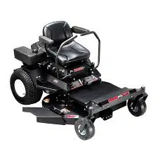
26 HP- 60" CUT
CELEBRATINGOVER60 YEARSOFINNOVATION
1945- 2007
1602 CORPORATE DRIVE, P.O. BOX 67, WARRENSBURG, MISSOURI 64093
PHONE 660-747-8183 FAX 660-747-8650
Manufacturing quality lawn care equipment since 1945
MadeUSAInThe I
12935
Rev. 07-009
OWNER'S MANUAL
STARTING SERIAL # L507-00100!
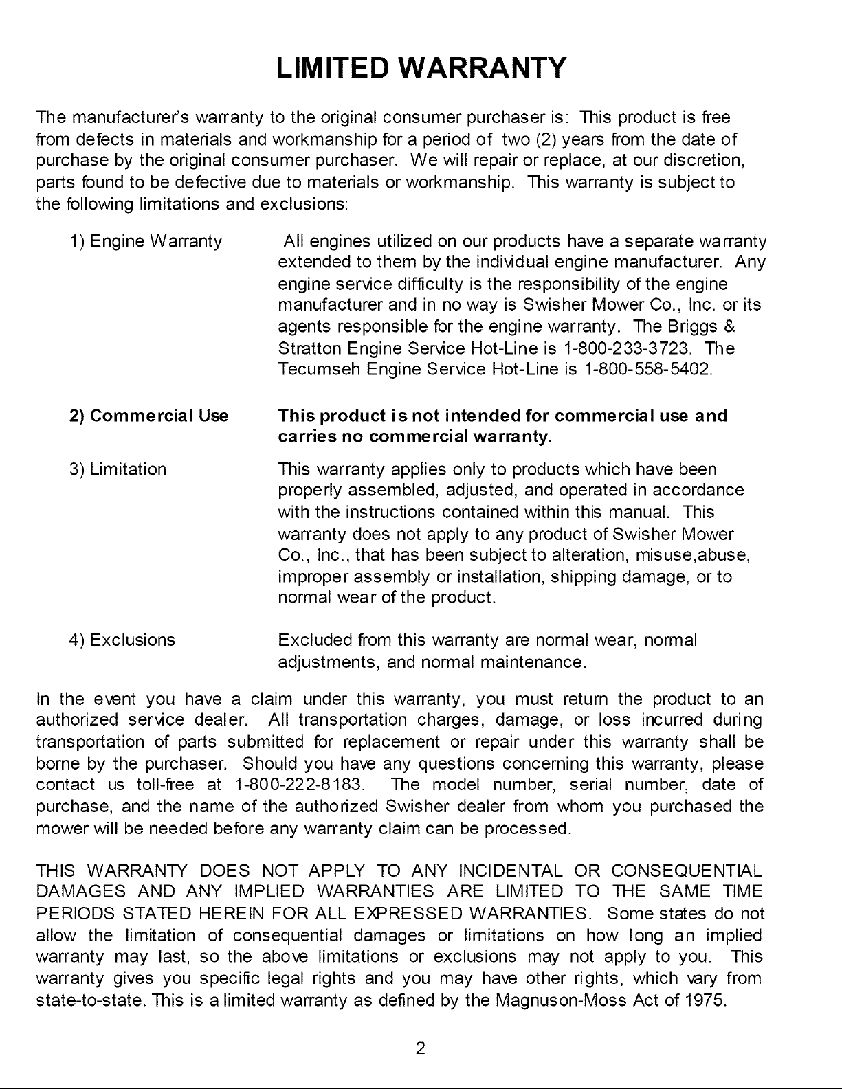
LIMITED WARRANTY
The manufacturer's warranty to the original consumer purchaser is: This product is free
from defects in materials and workmanship for a period of two (2) years from the date of
purchase by the original consumer purchaser. We will repair or replace, at our discretion,
parts found to be defective due to materials or workmanship. This warranty is subject to
the following limitations and exclusions:
1) Engine Warranty All engines utilized on our products have a separate warranty
extended to them by the individual engine manufacturer. Any
engine service difficulty is the responsibility of the engine
manufacturer and in no way is Swisher Mower Co., Inc. or its
agents responsible for the engine warranty. The Briggs &
Stratton Engine Service Hot-Line is 1-800-233-3723. The
Tecumseh Engine Service Hot-Line is 1-800-558-5402.
2) Commercial Use
3) Limitation
This product is not intended for commercial use and
carries no commercial warranty.
This warranty applies only to products which have been
properly assembled, adjusted, and operated in accordance
with the instructions contained within this manual. This
warranty does not apply to any product of Swisher Mower
Co., Inc., that has been subject to alteration, misuse,abuse,
improper assembly or installation, shipping damage, or to
normal wear of the product.
4) Exclusions Excluded from this warranty are normal wear, normal
adjustments, and normal maintenance.
In the event you have a claim under this warranty, you must return the product to an
authorized service dealer. All transportation charges, damage, or loss incurred during
transportation of parts submitted for replacement or repair under this warranty shall be
borne by the purchaser. Should you have any questions concerning this warranty, please
contact us toll-free at 1-800-222-8183. The model number, serial number, date of
purchase, and the name of the authorized Swisher dealer from whom you purchased the
mower will be needed before any warranty claim can be processed.
THIS WARRANTY DOES NOT APPLY TO ANY INCIDENTAL OR CONSEQUENTIAL
DAMAGES AND ANY IMPLIED WARRANTIES ARE LIMITED TO THE SAME TIME
PERIODS STATED HEREIN FOR ALL EXPRESSED WARRANTIES. Some states do not
allow the limitation of consequential damages or limitations on how long an implied
warranty may last, so the above limitations or exclusions may not apply to you. This
warranty gives you specific legal rights and you may have other rights, which vary from
state-to-state. This is a limited warranty as defined by the Magnuson-Moss Act of 1975.
Operator Presence ............. 12 ;i i_ i_
PARTS BREAKDOWNIIIIIIIII 27
Tires ................................ 12
.............................................................................................................................................................................................................................................................!:.................................................................................................................................................................................................................................................. ...........................................
Blade Maintenance .............. 13
!: 6_R 16ENTiFi CATION::: 37
B ry.........................! # ;_
i REP LACEME NT PARTS Zi i ill 38
V_be'{siiiiii iiiiiiiiiiiiiii4
_ sW_S HER H ISi O _Y ............ 40
Overall Unit C are ................ 14
......................TranspoSing Saf_iy :::::::::::: 14 ................................................................................................................................................................................................
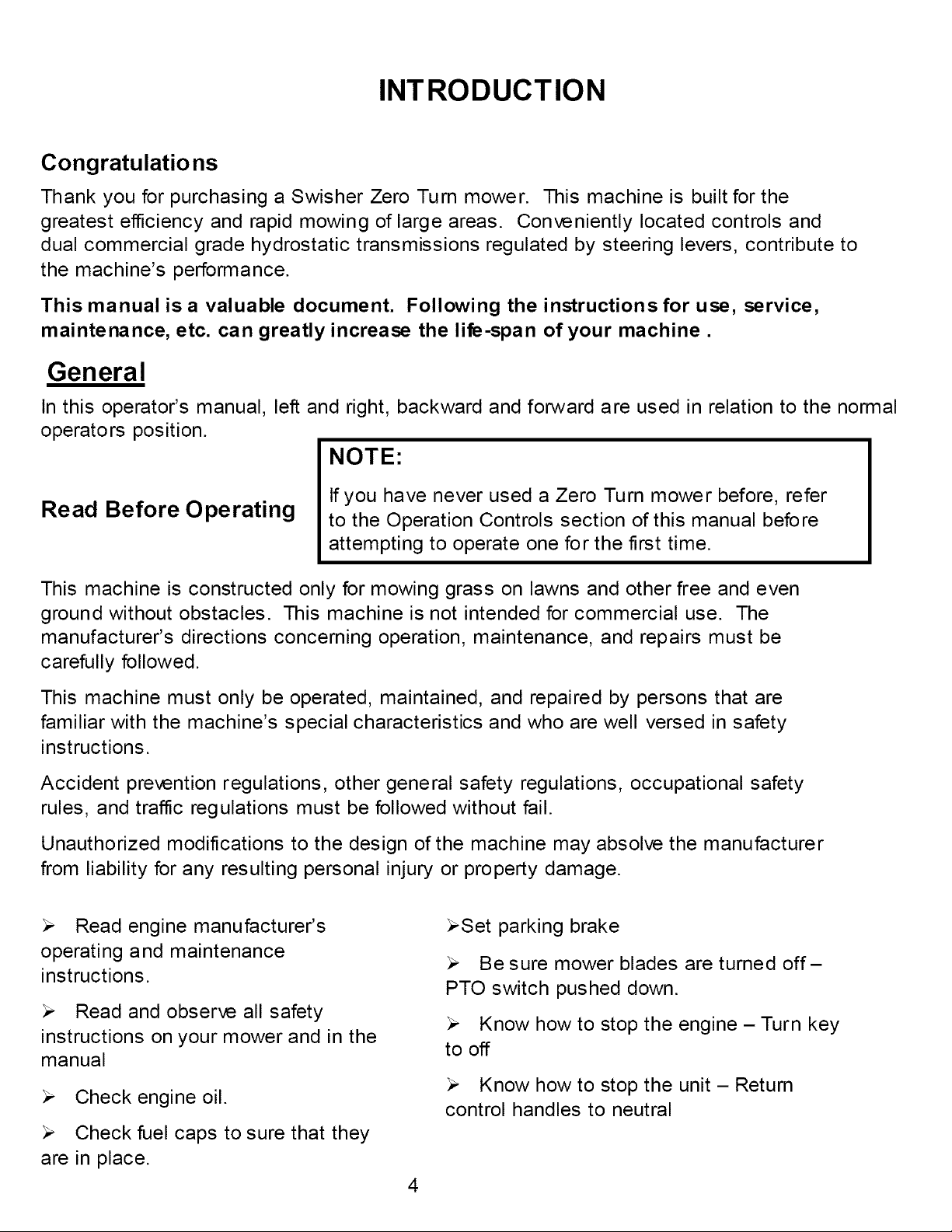
INTRODUCTION
Congratulations
Thank you for purchasing a Swisher Zero Turn mower. This machine is built for the
greatest efficiency and rapid mowing of large areas. Conveniently located controls and
dual commercial grade hydrostatic transmissions regulated by steering levers, contribute to
the machine's performance.
This manual is a valuable document. Following the instructions for use, service,
maintenance, etc. can greatly increase the life-span of your machine.
General
In this operator's manual, left and right, backward and forward are used in relation to the normal
operators position.
NOTE:
Read Before Operating
If you have never used a Zero Turn mower before, refer
to the Operation Controls section of this manual before
attempting to operate one for the first time.
This machine is constructed only for mowing grass on lawns and other free and even
ground without obstacles. This machine is not intended for commercial use. The
manufacturer's directions concerning operation, maintenance, and repairs must be
carefully followed.
This machine must only be operated, maintained, and repaired by persons that are
familiar with the machine's special characteristics and who are well versed in safety
instructions.
Accident prevention regulations, other general safety regulations, occupational safety
rules, and traffic regulations must be followed without fail.
Unauthorized modifications to the design of the machine may absolve the manufacturer
from liability for any resulting personal injury or property damage.
Read engine manufacturer's
operating and maintenance
instructions.
Read and observe all safety
instructions on your mower and in the
manual
Check engine oil.
Check fuel caps to sure that they
are in place.
_Set parking brake
Be sure mower blades are turned off-
PTO switch pushed down.
Know how to stop the engine - Turn key
to off
Know how to stop the unit - Return
control handles to neutral
4
INTRODUCTION
Uncrating & Assembly
TOOLS REQUIRED:
,/ 2 - ½" Wrenches or ½" Socket with drive ratchet
,/ Tire pressure gauge
,/ Nail bar or claw hammer
,/ Wire snips
To Remove The Mower From The Crate
Dispose of top and side panels of the crate.
Remove loose parts and packing material
Cut any banding or strapping that may be holding the mower to the crate.
Disengage spark plug wire and place where it cannot make a connection.
Raise the mower deck to its highest position..
Disengage the parking brakes by placing the handle controls in the upright position.
Open the transmission valves at the rear of the unit by pulling the release rods and
locking them in place. SEE INSTRUCTION DECAL AT THE REAR OF THE UNIT.
Carefully push the mower off the crate to a safe and level area.
Check engine oil. All engines are filled with oil and tested at the factory. Verify oil
level and add if necessary before starting engine. SEE ENGINE OWNER'S MANUAL
Check the battery. If the battery is put into service after the "month & year" of the
date on the battery, then it may need to be charged with a 12 volt charger for a minimum
of 1 hour, but no more than 2 hours at a rate of 6 to 10 amps.
Attach battery cables to battery. Always attach the positive terminal first.
Install steering levers. Remove the bolts from the control arms on the mower. Align
the holes in the lever with the holes in the control arms and attach with the bolts provided.
Make sure both bolts on both handles are tight.
Close the transmission valves at the rear of the unit. SEE INSTRUCTION DECAL
AT THE REAR OF THE UNIT.
Reconnect spark plug wire.
Check tire pressure on all four wheels. REFER TO UNIT SPECIFICATIONS TABLE
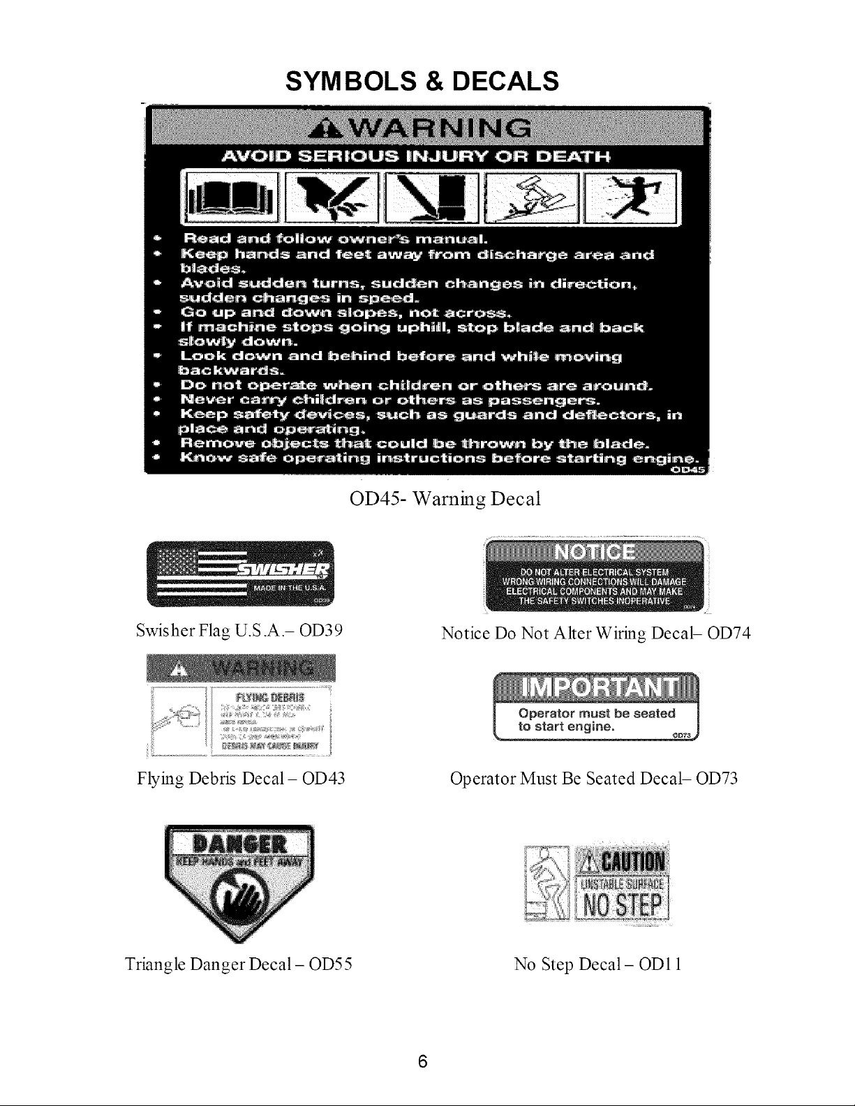
SYMBOLS & DECALS
Swisher Flag U.S.A.- OD39
OD45- Warning Decal
Notice Do Not Alter Wiring Decal- OD74
Flying Debris Decal- OD43 Operator Must Be Seated Decal- OD73
Triangle Danger Decal- OD55 No Step Decal- OD11
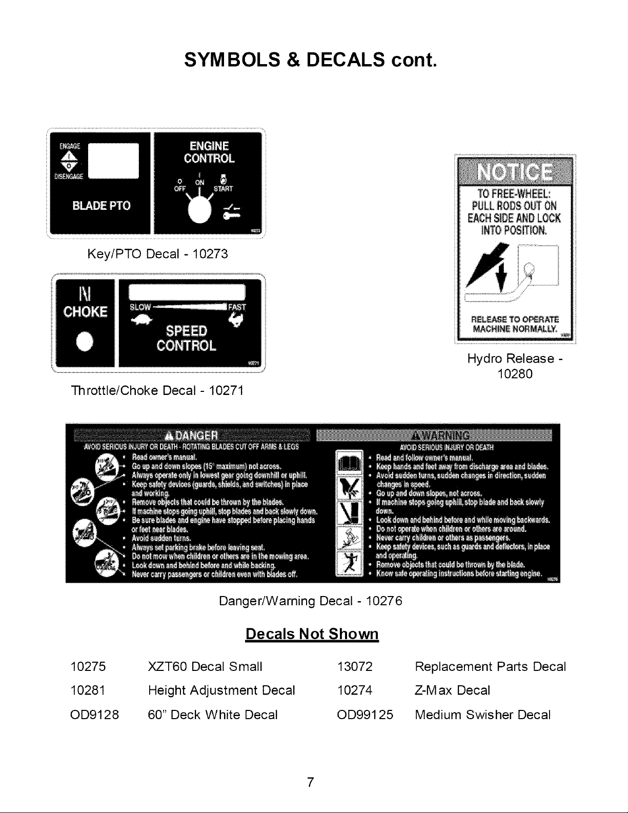
SYMBOLS & DECALS cont.
Key/PTO Decal-10273
Throttle/Choke Decal- 10271
RELFL_E TOO_:_ATE
NACN!f4_ N_MALLY,
Hydro Release -
10280
Danger/Warning Decal- 10276
Decals Not Shown
10275
10281
OD9128
XZT60 Decal Small
Height Adjustment Decal
60" Deck White Decal
13072
10274
OD991 25
Replacement Parts Decal
Z-M ax Decal
Medium Swisher Decal
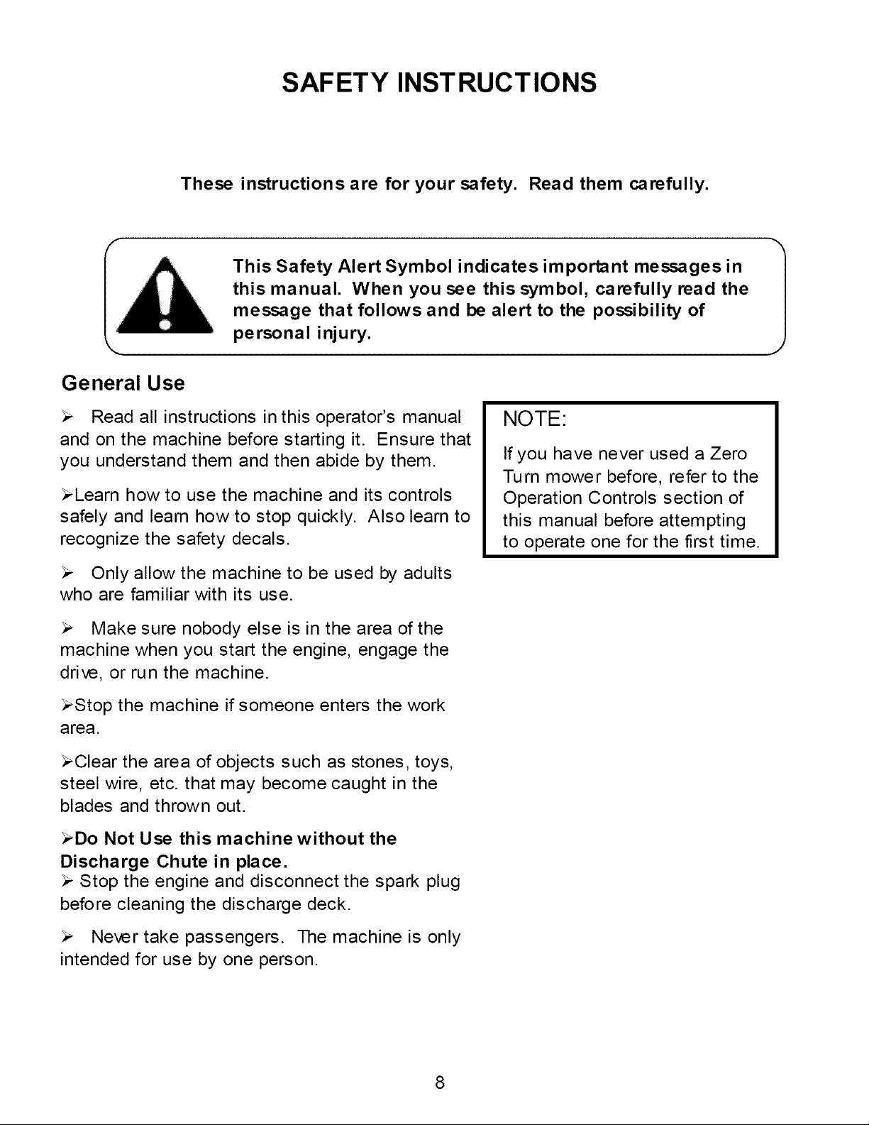
SAFETY INSTRUCTIONS
These instructions are for your safety. Read them carefully.
This Safety Alert Symbol indicates important messages in
this manual. When you see this symbol, carefully read the
message that follows and be alert to the possibility of
personal injury.
General Use
Read all instructions in this operator's manual
and on the machine before starting it. Ensure that
you understand them and then abide by them.
_Learn how to use the machine and its controls
safely and learn how to stop quickly. Also learn to
recognize the safety decals.
Only allow the machine to be used by adults
who are familiar with its use.
NOTE:
If you have never used a Zero
Turn mower before, refer to the
Operation Controls section of
this manual before attempting
to operate one for the first time.
Make sure nobody else is in the area of the
machine when you start the engine, engage the
drive, or run the machine.
_Stop the machine if someone enters the work
area.
_Clear the area of objects such as stones, toys,
steel wire, etc. that may become caught in the
blades and thrown out.
_Do Not Use this machine without the
Discharge Chute in place.
Stop the engine and disconnect the spark plug
before cleaning the discharge deck.
Never take passengers. The machine is only
intended for use by one person.
1
SAFETY INSTRUCTIONS
General Use Continued
_Always look around before and during reversing
maneuvers.
Slow down before turning.
Shut down the mower deck when not mowing.
Be careful when rounding fixed objects, so that
the blades do not hit them.
Only operate the machine in daylight or other
well-lit conditions.
Keep the machine a safe distance from holes
or other irregularities in the ground.
Never use the machine if you are tired, if you
have consumed alcohol, or if you are taking other
drugs or medications that can affect your vision,
judgment, or coordination.
Beware of traffic when working near or
crossing a road.
Never leave the machine unsupervised with
the engine running. Always shut down the blades,
engage the parking brakes, stop the engine, and
remove the ignition key before leaving the
machine.
Never allow children or other persons not
trained in the use of the machine to use or service
it. Local laws may regulate the age of the user.
Make sure that you have first aid equipment
close at hand when using the machine.
Never use the machine when barefoot. Always
wear protective shoes or boots.
Always wear approved protective glasses or a
full visor when assembling or driving.
Ear Protection is recommended
Never wear loose clothing that can get caught in
moving parts.
9
Remember
The operator is responsible
for avoiding dangers or
accidents.
WARN ING
When using the
machi ne, approved
personal protective
equipment shall be
used. Personal
protective
equipment cannot
eliminate the risk of
injury, but it will
reduce the degree of
injury if an accident
does occur. Ask
your retailer for help
in choosing the right
equipment.
SAFETY INSTRUCTIONS
Slope Operation
Remove obstacles such as stones, tree branches, etc.
Mow up and down, not side to side. Never drive the rider
on terrain that slopes more than 10 degrees.
Avoid starting or stopping on a slope. If the tires begin to
slip, shut down the blades and drive slowly down the slope.
Always drive evenly and slowly on slopes.
Make no sudden changes in speed or direction.
Avoid unnecessary turns on slopes, and if it proves
necessary, turn slowly and gradually downward, if possible.
Watch for holes, ruts, or bumps. On uneven terrain, the
machine can tip more easily. Long grass can hide obstacles.
Drive slowly and use small movements of the steering
controls.
Do not mow wet grass. It is slippery, and the tires can
loose their grip, so that the machine slides.
Do not try to stabilize the machine by putting a foot on the
ground.
Children
Serious accidents may occur if you fail to be on guard for
children in the area of the machine. Children are often
attracted to the machine and mowing work. Never assume that
children will stay put where you last saw them.
Keep children away from the mowing area and under close
supervision by another adult.
Shut off the machine if children enter the work area.
Never allow a child to ride with you.
Never allow children to operate the machine.
Be extra cautious near corners, bushes, trees, or other
objects that block your view.
Remember
The operator is
responsible for
avoiding dangers or
accidents.
10
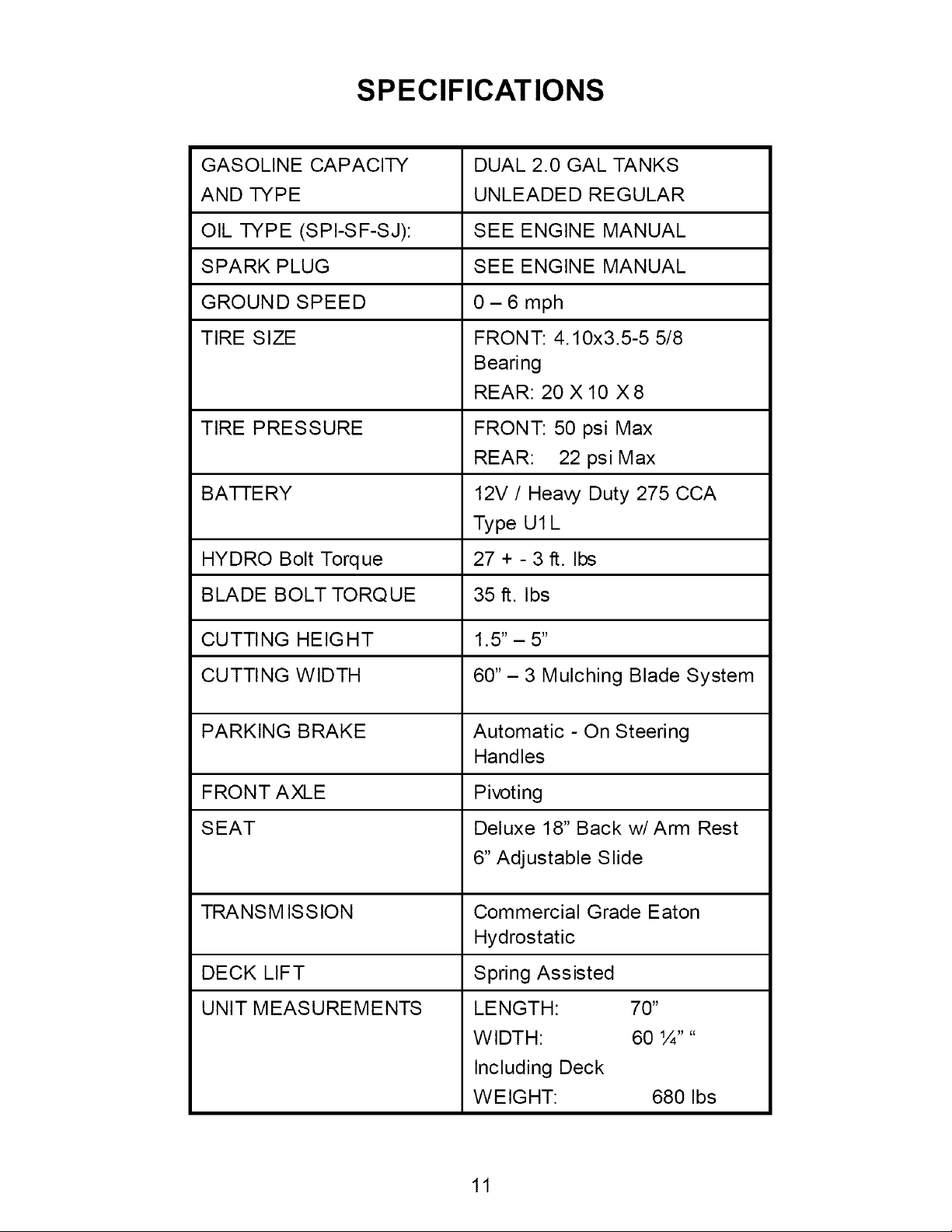
SPECIFICATIONS
GASOLINE CAPACITY DUAL 2.0 GAL TANKS
AND TYPE UNLEADED REGULAR
OIL TYPE (SPI-SF-SJ): SEE ENGINE MANUAL
SPARK PLUG SEE ENGINE MANUAL
GROUND SPEED 0- 6 mph
TIRE SIZE FRONT: 4.10x3.5-5 5/8
Bearing
REAR: 20 X 10 X 8
TIRE PRESSURE FRONT: 50 psi Max
REAR: 22 psi Max
BA-I-I-ERY 12V / Heavy Duty 275 CCA
Type Ul L
HYDRO Bolt Torque 27 + - 3 ft. Ibs
BLADE BOLT TORQUE 35 ft. Ibs
CUTTING HEIGHT 1.5"- 5"
CUTTING WIDTH 60"- 3 Mulching Blade System
PARKING BRAKE Automatic - On Steering
Handles
FRONT AXLE Pivoting
SEAT Deluxe 18" Back w/Arm Rest
6" Adjustable Slide
TRANSMISSION Commercial Grade Eaton
Hydrostatic
DECK LIFT Spring Assisted
UNIT MEASUREMENTS LENGTH: 70"
WIDTH: 60 ¼ ....
Including Deck
WEIGHT: 680 Ibs
11

CUSTOMER RESPONSIBILITIES
Operator Presence Syste m
Be sure the operator presence and interlock systems are working properly. If your
mower does not function as described, repair the problem immediately.
The engine should not start unless the parking brakes (handle controls)
are engaged (rotated outward), the PTO (Blade Engagement - See
OPERATION FEATURES section of this manual) switch is disengaged
(pressed down), and the operator is on the seat.
When the engine is running, any attempt by the operator to leave the seat
without first setting the parking brake should shut off the engine.
When the engine is running and the PTO switch is engaged, any attempt
by the operator to leave the seat without first disengaging the PTO switch,
should shut off the engine.
When the engine is running and the control levers are rotated in, any
attempt by the operator to leave the seat without rotating the control levers
out, should shut off the engine.
The PTO switch should never engage without the operator on the seat.
Tires
Maintain proper air pressure in all tires ( SEE SPECIFICATIONS section)
Keep tires free of gasoline, oil, or insect control chemicals which can harm
rubber.
Avoid stumps, stones, deep ruts, sharp objects and other hazards that
may cause tire damage.
12

CUSTOMER RESPONSIBILITIES
Blade Maintenance
CAUTION
Stop engine and remove ignition key for safety. Disconnect spark plug wire. Wear
heavy, thick gloves when holding onto blade. Avoid the sharp edge of the blade.
For best results, mower blades must be kept sharp.
Safely raise front of mower. SEE WARNING
Hold or block blade from turning.
Loosen blade nut and remove blade.
Replace blade, (SEE SPECIF ICAT IONS).
Battery
WARNING
The battery contains sulfuric acid
and electrolytes which are
poisonous and corrosive.
Replace bent or damage blades.
WARNI NG
When it is necessary to raise
the mower for any repair or
service, use jackstands to
provide adequate support.
DO NOT rely on hydraulic or
mechanical jacks
The battery is a maintenance-free battery and the fluid level cannot be checked.
Charge battery if needed.
To clean battery and terminals
Remove terminal guard.
_-Disconnect the BLACK battery cable first, then the RED battery cable and remove
the battery.
Rinse the battery with plain water and dry.
Clean terminals and battery cable ends with wire brush until shiny.
Coat terminals with grease or petroleum jelly
Reinstall battery
Reconnect the battery cables
13
CUSTOMER RESPONSIBILITIES
V-Belts
Check V-belts for deterioration and wear after 100 hours of operation and replace if
necessary. Replace belts if they begin to slip from wear. SEE SPECIFICATION for belt
part numbers and SERVICE section of this manual for instructions on how to replace the
belt.
Engine
REFER TO YOUR ENGINE OWNERS MANUAL
Overall Unit Care
Reduce the risk of fire by removing grass, leaves, and other debris that may
have accumulated on the machine. Allow the machine time to cool before
cleaning or putting it in storage.
Wash mower periodically. Clean above and below deck.
Keep all electrical connections clean and tight.
Driving and Transport on Public Roads
_Check applicable road traffic regulations before driving and transporting on public
roads.
_lf the machine is transported, you should always use approved fastening equipment
and ensure that the machine is well anchored.
_-The cutting deck should also be lowered to the lowest position and the steering
levers should be in the outward position, so that the parking brake is engaged.
14
CUSTOMER RESPONSIBILITIES
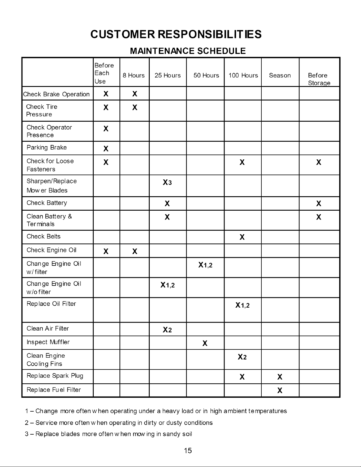
MAINTENANCE SCHEDULE
Before
Each 8 Hours 25 Hours 50 Hours 100 Hours Season Before
Use Stora,qe
Check Brake Operation X X
Check Tire X X
Pressure
Check Operator X
Presence
Parking Brake X
Check for Loose X X X
Fasteners
Sharpen/Repl ace X3
Mow er Blades
Check Battery X X
Clean Battery & X X
Ter mina ts
Check Belts X
Check Engine Oil X X
Change Engine Oil Xl,2
w/filter
Change Engine Oil Xl,2
w/o filter
Replace Oil Filter Xl,2
Clean Air Filter X2
Inspect Muffler X
Clean Engine X2
Cooling Fins
Replace Spark Plug X X
Replace Fuel Filter X
1 - Change more often w hen operating under a heavy load or in high ambient temperatures
2 - Service more often w hen operating in dirty or dusty conditions
3 - Replace blades more often w hen mow ing in sandy soil
15
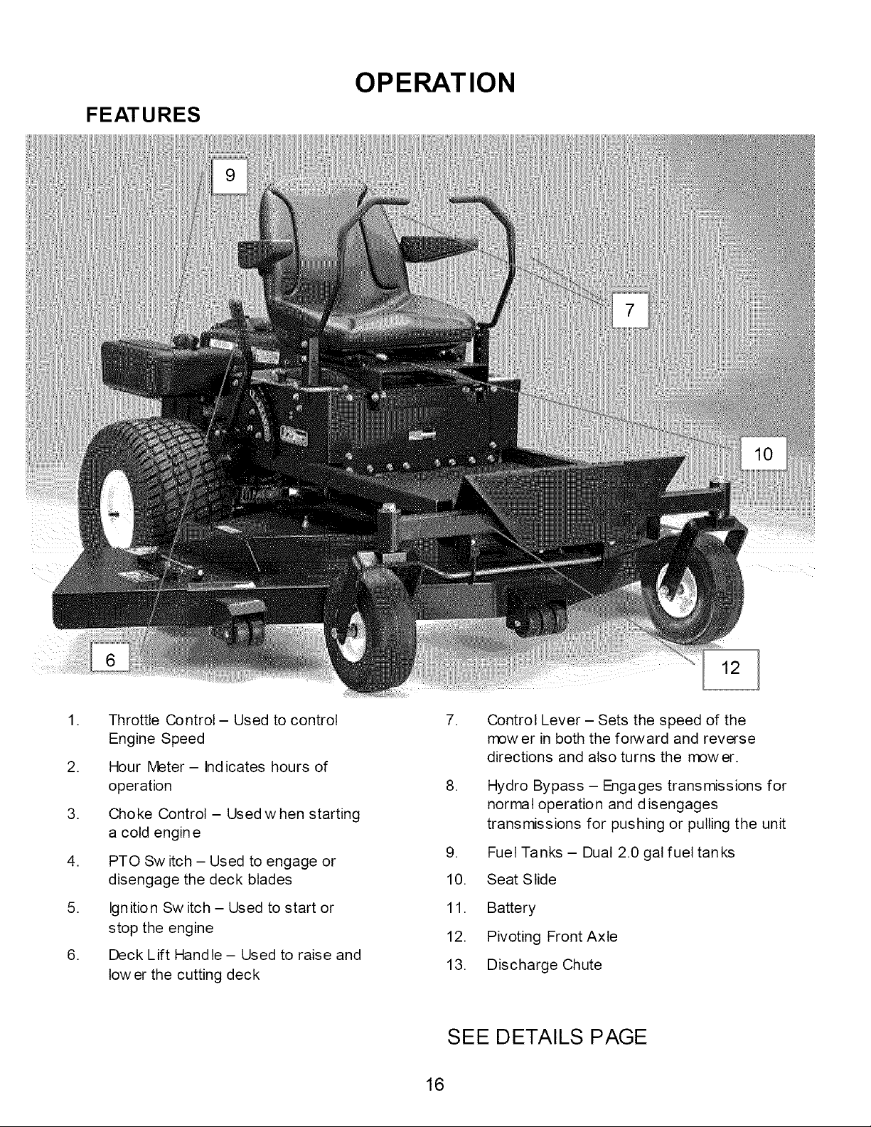
FEATURES
OPERATION
,
,
,
,
,
,
Throttle Control - Used to control
Engine Speed
Hour Meter- Indicates hours of
operation
Choke Control- Used when starting
a cold engine
PTO Sw itch - Used to engage or
disengage the deck blades
Ignition Sw itch - Used to start or
stop the engine
Deck Lift Handle - Used to raise and
low er the cutting deck
7. Control Lever - Sets the speed of the
mow er in both the forward and reverse
directions and also turns the mower.
8. Hydro Bypass - Engages transmissions for
normal operation and disengages
transmissions for pushing or pulling the unit
9. Fuet Tanks - Dual 2.0 gal fuel tanks
10. Seat Slide
11. Battery
12. Pivoting Front Axle
13. Discharge Chute
SEE DETAILS PAGE
16
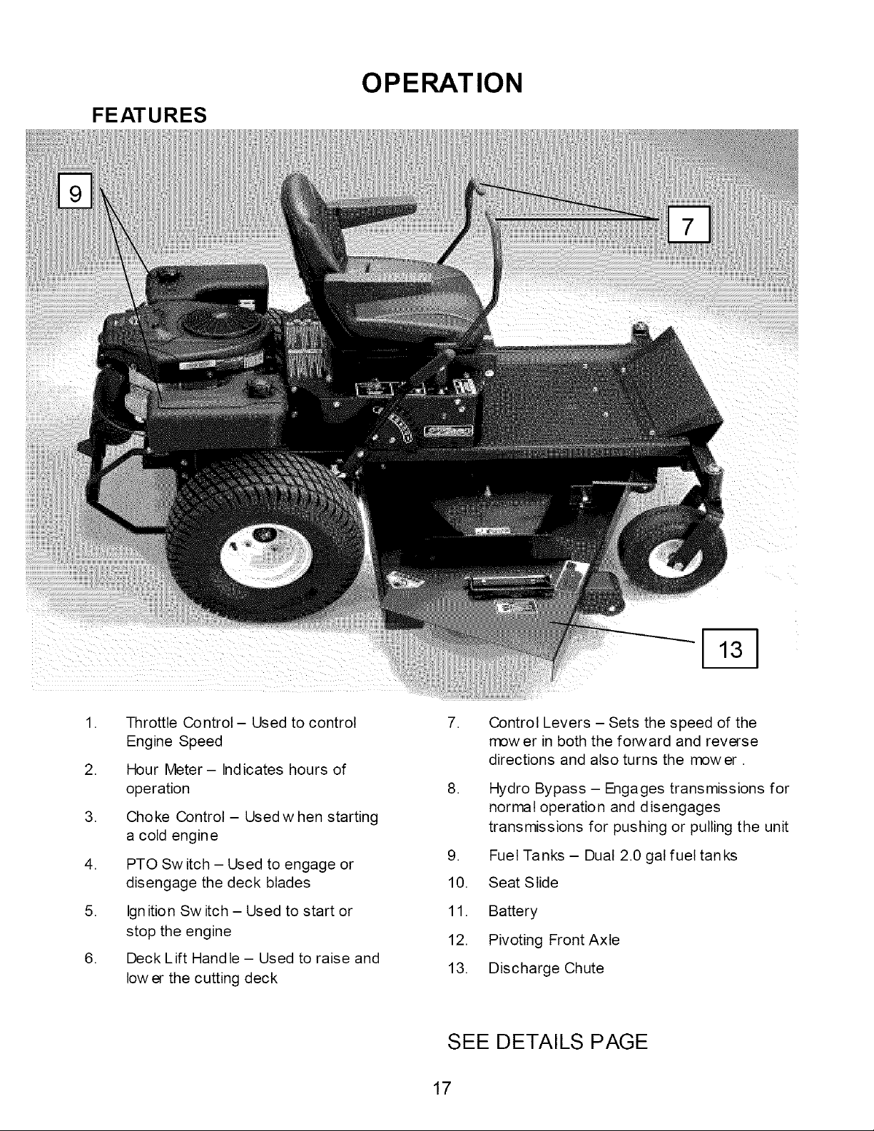
FEATURES
OPERATION
1. Throttle Control- Used to control
Engine Speed
2. Hour Meter- Indicates hours of
operation
3. Choke Control - Used w hen starting
a cold engine
4. PTO Sw itch - Used to engage or
disengage the deck blades
5. Ignition Sw itch - Used to start or
stop the engine
6. Deck Lift Hand le - Used to raise and
low er the cutting deck
7. Control Levers - Sets the speed of the
mow er in both the forward and reverse
directions and also turns the mower.
8. Hydro Bypass - Engages transmissions for
normal operation and d is engages
transmissions for pushing or pulling the unit
9. Fuet Tanks - Dual 2.0 gal fuel tanks
10. Seat Slide
11. Battery
12. Pivoting Front Axle
13. Discharge Chute
SEE DETAILS PAGE
17
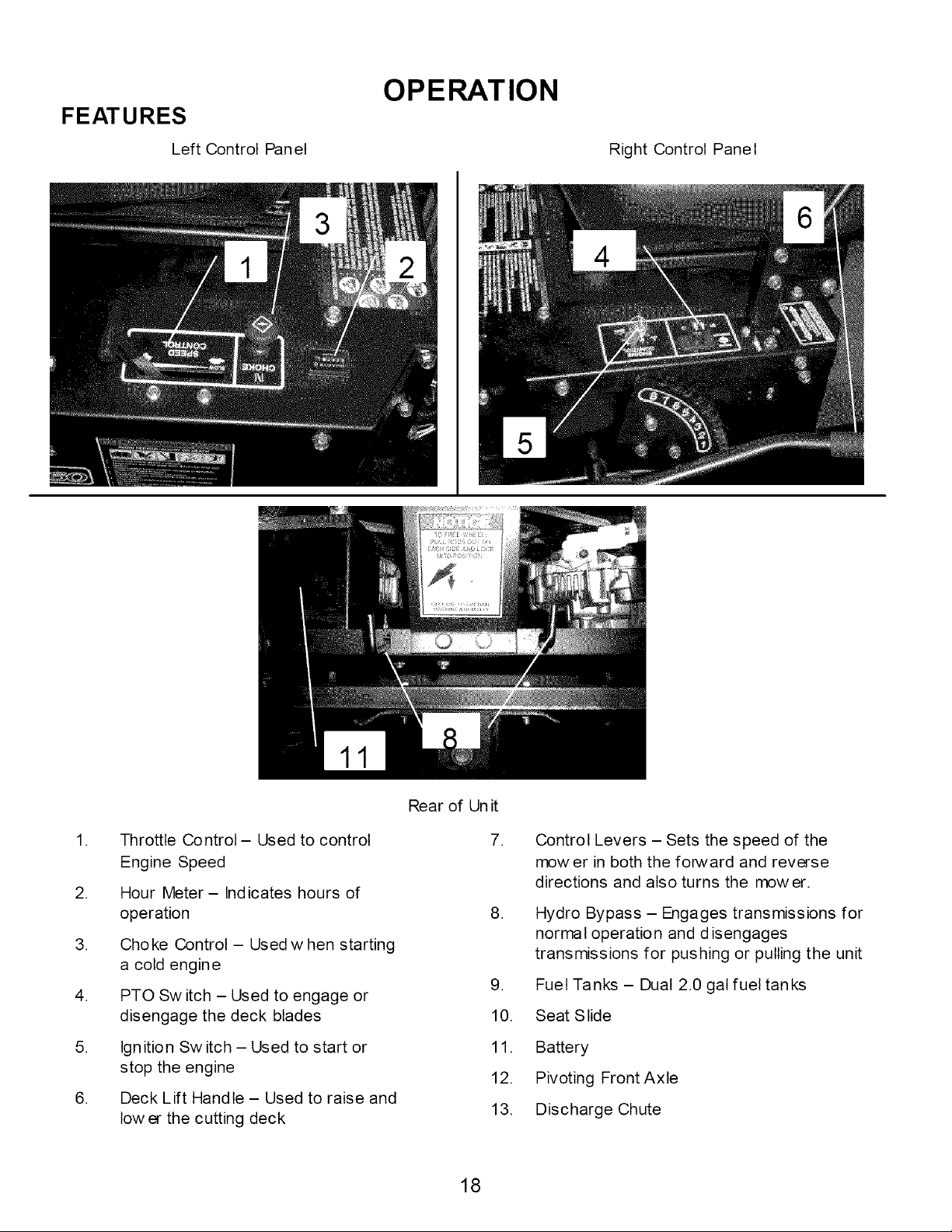
FEATURES
Left Control Panel
OPERATION
Right Control Panel
1. Throttle Control- Used to control
Engine Speed
2. Hour Meter- Indicates hours of
operation
3. Choke Control - Used w hen starting
a cold engine
4. PTO Sw itch - Used to engage or
disengage the deck blades
5. Ign ition Sw itch - Used to start or
stop the engine
6. Deck Lift Handle - Used to raise and
low er the cutting deck
Rear of Un it
7.
Control Levers - Sets the speed of the
mow er in both the forward and reverse
directions and also turns the mower.
8. Hydro Bypass - Engages transmissions for
normal operation and disengages
transmissions for pushing or pulling the unit
9. Fuet Tanks - Dual 2.0 gal fuel tanks
10. Seat Slide
11. Battery
12. Pivoting FrontAxle
13. Discharge Chute
18
OPERATION
Starting
Operator must be sitting in the seat. Control handles must be in the neutral
(outward) position. Parking brake must be on. PTO must be in the disengage
position (pushed down).
Set choke (if needed), turn key and release as soon as engine starts. Adjust
throttle to half and shut choke off.
Close motion control levers (move inward), releasing the Parking Brakes
Be sure all people are clear of the area. Engage blades and set RPM to
maximum.
Grass Height & Cutting Suggestions
Do not attempt to cut wet grass
NOTE:
If you have never used a Zero
Turn mower before, refer to the
Operation Controls section of
this manual before attempting
to operate one for the first time.
The average lawn should be cut to 2 ½" during the cool season and to over 3"
during the hot months. For healthier and better looking lawns, mow often and after
moderate growth.
As a rule, never cut more than 1/3 of the total grass blade length. Correct
mowing height can reduce weeds and lawn disease.
For best performance, grass over 6 inches in height should be mowed twice.
The first cut should be set relatively high and the second set to the desired height.
19
Controls
OPERATION
Be familiar with all controls, their functions and how to operate them before
starting the machine.
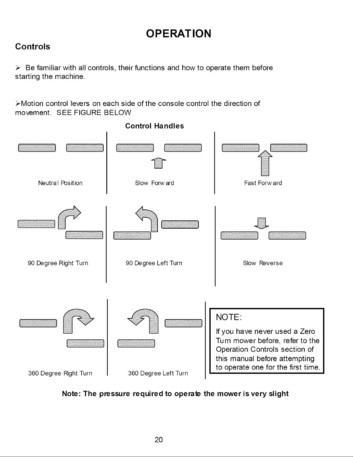
_Motion control levers on each side of the console control the direction of
movement. SEE FIGURE BELOW
Control Handles
Neutral Position Stow Forward Fast Forward
90 Degree Right Turn 90 Degree Left Turn
Slow Reverse
360 Degree Right Turn 360 Degree Left Turn
NOTE:
If you have never used a Zero
Turn mower before, refer to the
Operation Controls section of
this manual before attempting
to operate one for the first time.
Note: The pressure required to operate the mower is very slight
20
SERVICE & ADJUSTMENTS
Adjusting The Cutting Height
Push out on the Deck Lift Handle and raise or lower the deck to the desired
position.
Position 1 is the lowest setting and Position 8 is the highest position
The cutting range is from approximately 1 ½" to approximately 5"
Deck Leveling
TOOLS REQUIRED:
,/ 2 - ½" Wrenches or ½" Socket with drive ratchet
Lower the cutting deck down to the lowest position (position 1)
Loosen the nuts on the top side of the deck hanger brackets (3 places) where
the lift cables attach to.
With all three loose on top of the brackets the deck should now set on the
ground resting on the roller wheels.
Tighten the nuts on the top of the lift brackets making sure that all three lift
cables are pulled tight.
Lift deck using the deck lift handle to the desired position
21
SERVICE & ADJUSTMENTS
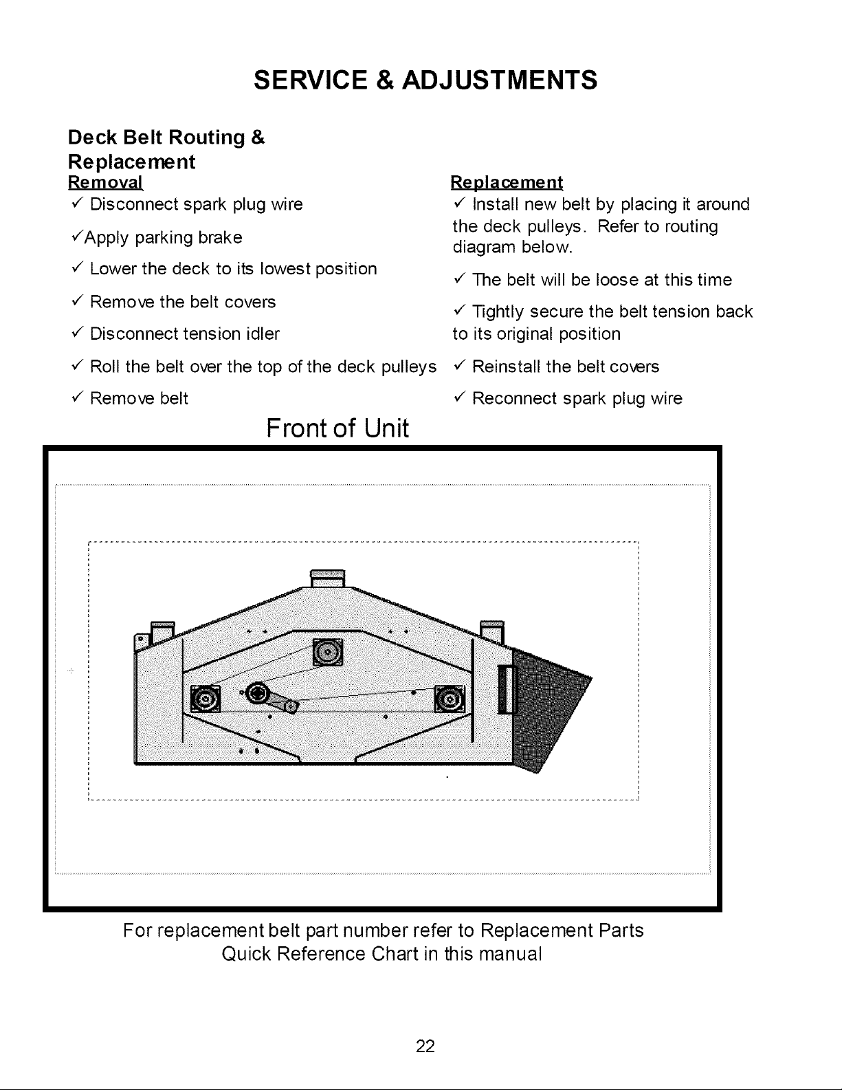
Deck Belt Routing &
Replacement
Re m oval
`/Disconnect spark plug wire
,/Apply parking brake
,/Lower the deck to its lowest position
,/Remove the belt covers
,/Disconnect tension idler
,/Roll the belt over the top of the deck pulleys
,/Remove belt
Front of Unit
Replacement
,/Install new belt by placing it around
the deck pulleys. Refer to routing
diagram below.
,/The belt will be loose at this time
,/Tightly secure the belt tension back
to its original position
,/Reinstall the belt covers
,/Reconnect spark plug wire
For replacement belt part number refer to Replacement Parts
Quick Reference Chart in this manual
22
SERVICE & ADJUSTMENTS
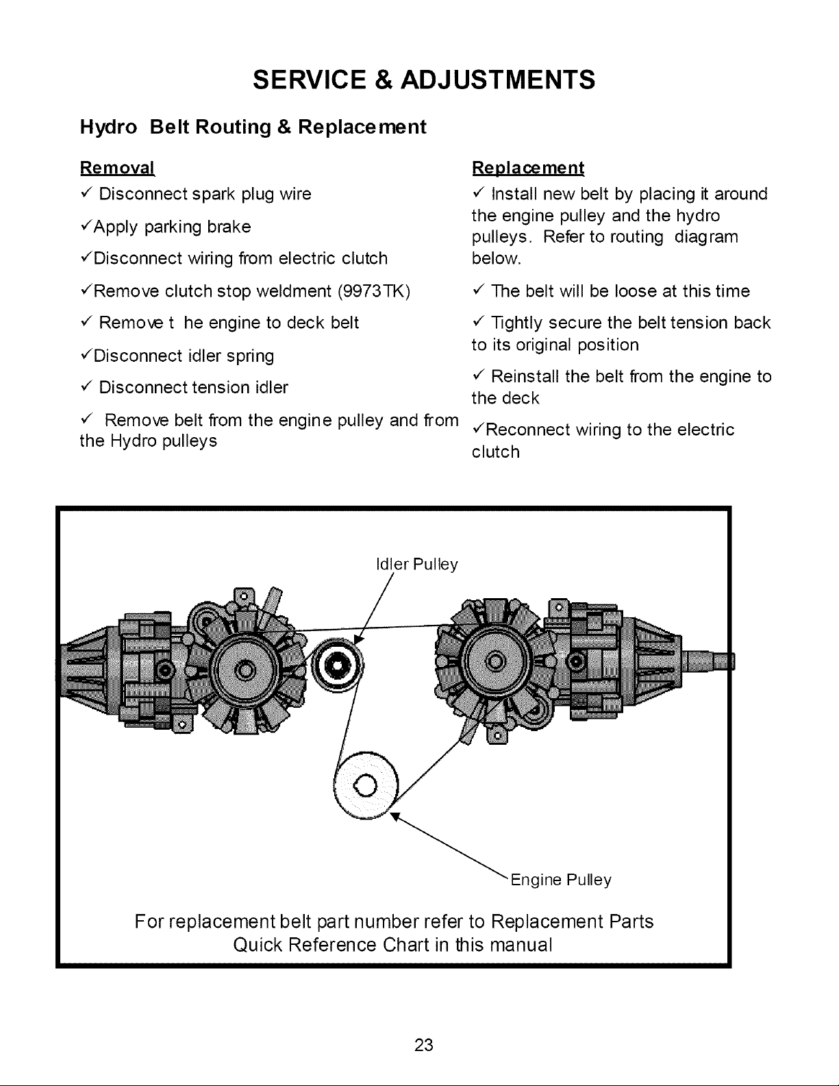
Hydro Belt Routing & Replacement
Removal
,/Disconnect spark plug wire
,/Apply parking brake
,/Disconnect wiring from electric clutch
,/Remove clutch stop weldment (9973TK)
,/Remove t he engine to deck belt
,/Disconnect idler spring
,/Disconnect tension idler
,/ Remove belt from the engine pulley and from
the Hydro pulleys
Replacement
,/Install new belt by placing it around
the engine pulley and the hydro
pulleys. Refer to routing diagram
below.
,/The belt will be loose at this time
,/Tightly secure the belt tension back
to its original position
,/Reinstall the belt from the engine to
the deck
,/Reconnect wiring to the electric
clutch
Idler Pulley
Engine Pulley
For replacement belt part number refer to Replacement Parts
Quick Reference Chart in this manual
23
SERVICE & ADJUSTMENTS
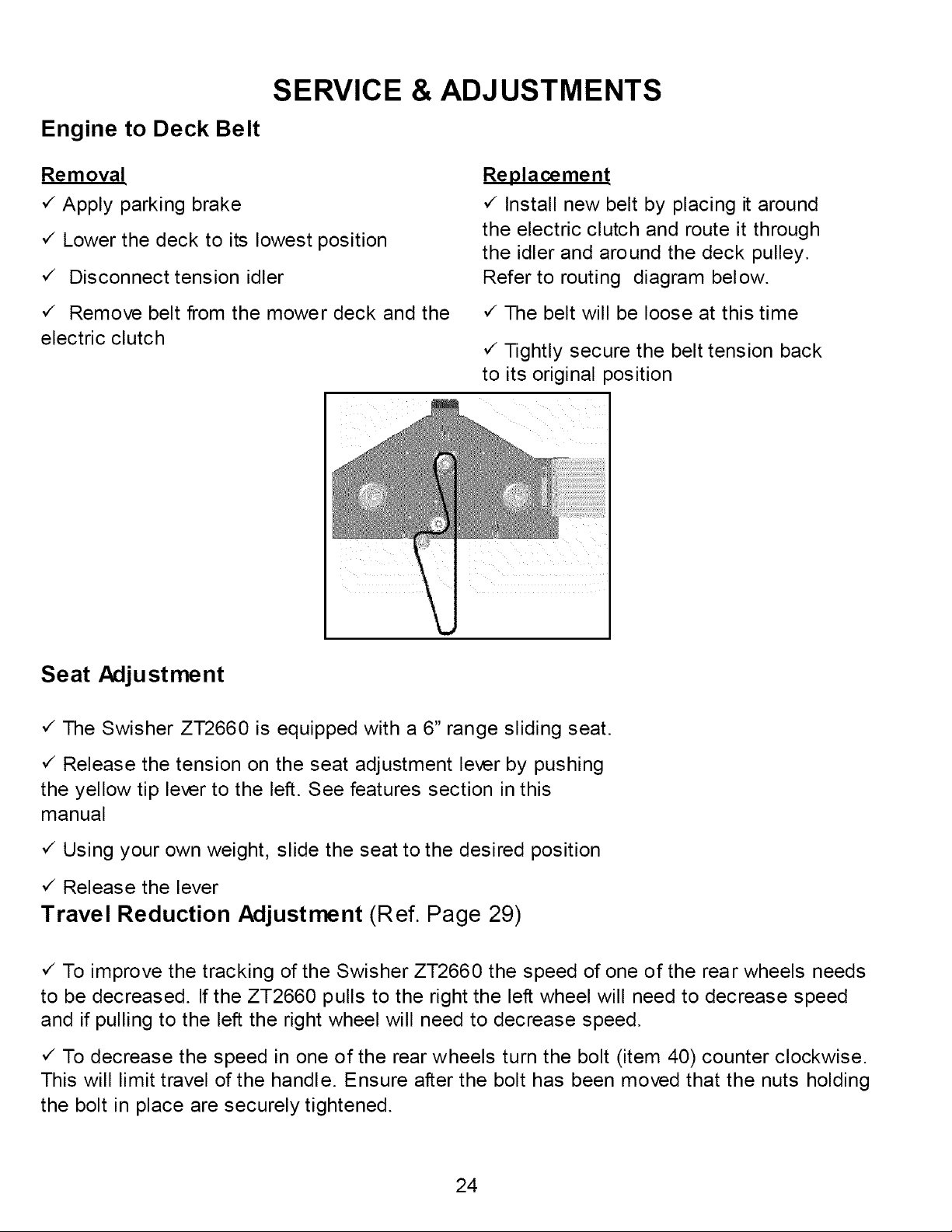
Engine to Deck Belt
Removal
,/Apply parking brake
v_ Lower the deck to its lowest position
,/ Disconnect tension idler
,/ Remove belt from the mower deck and the
electric clutch
Replacement
,/Install new belt by placing it around
the electric clutch and route it through
the idler and around the deck pulley.
Refer to routing diagram below.
,/The belt will be loose at this time
,/Tightly secure the belt tension back
to its original position
Seat Adju stment
¢ The Swisher ZT2660 is equipped with a 6" range sliding seat.
¢ Release the tension on the seat adjustment lever by pushing
the yellow tip lever to the left. See features section in this
manual
v_Using your own weight, slide the seat to the desired position
v_Release the lever
Travel Reduction Adjustment (Ref. Page 29)
v_ To improve the tracking of the Swisher ZT2660 the speed of one of the rear wheels needs
to be decreased. If the ZT2660 pulls to the right the left wheel will need to decrease speed
and if pulling to the left the right wheel will need to decrease speed.
,/To decrease the speed in one of the rear wheels turn the bolt (item 40) counter clockwise.
This will limit travel of the handle. Ensure after the bolt has been moved that the nuts holding
the bolt in place are securely tightened.
24
SERVICE & ADJUSTMENTS
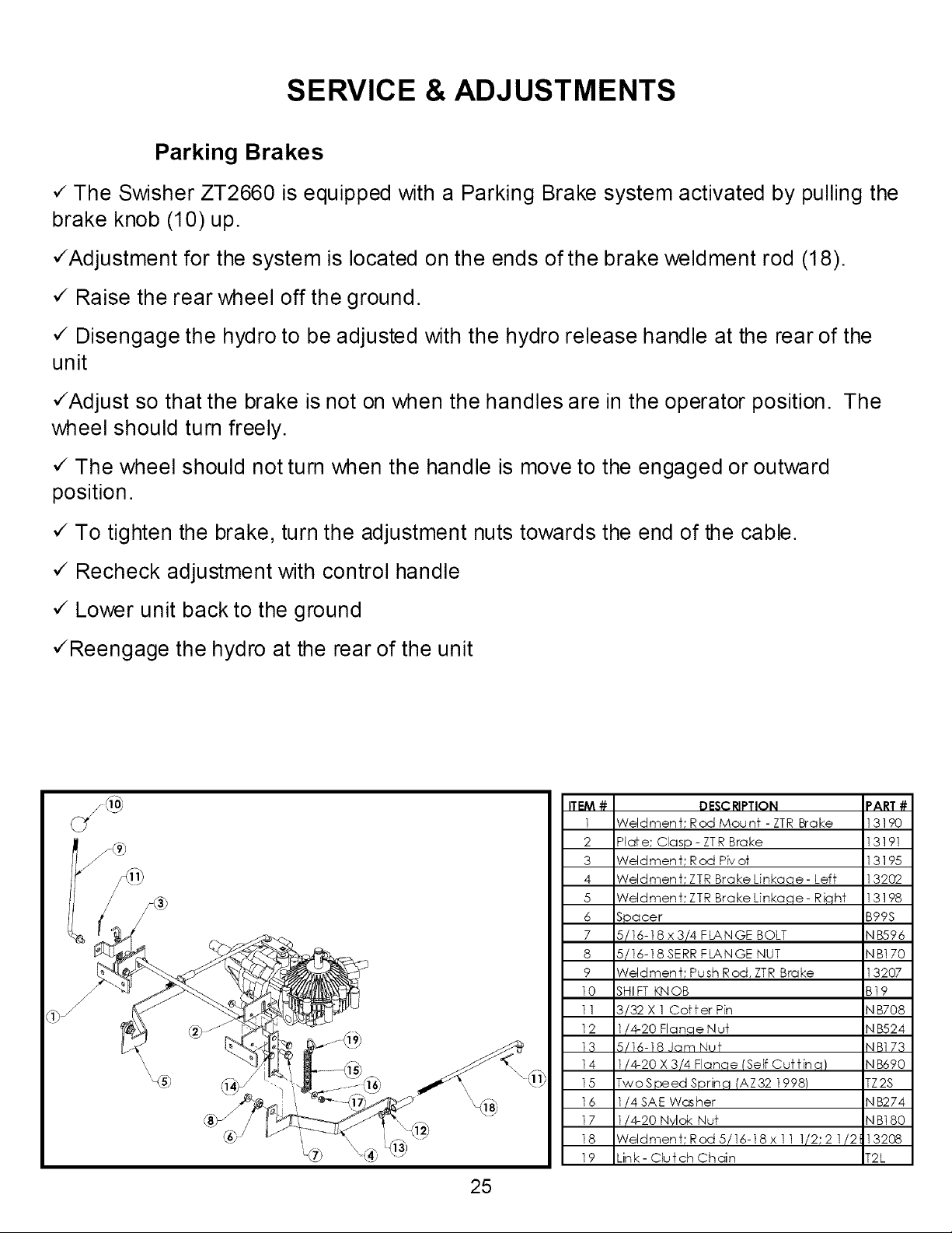
Parking Brakes
,/The Swisher ZT2660 is equipped with a Parking Brake system activated by pulling the
brake knob (10) up.
,/Adjustment for the system is located on the ends of the brake weldment rod (18).
,/Raise the rear wheel off the ground.
,/Disengage the hydro to be adjusted with the hydro release handle at the rear of the
unit
,/Adjust so that the brake is not on when the handles are in the operator position. The
wheel should turn freely.
,/The wheel should not turn when the handle is move to the engaged or outward
position.
,/To tighten the brake, turn the adjustment nuts towards the end of the cable.
,/Recheck adjustment with control handle
,/Lower unit back to the ground
,/Reengage the hydro at the rear of the unit
25
ITEM #
]
2
3
4
5
6
7
8
9
10
11
12
13
14
15
16
17
18
19
DESC RIPTION PART #
Weldment; Rod Mounf -ZTR Brake 13190
Plaf e; Clasp - ZTR Brake 13191
Weld men t; Rod Piv of 13195
Weldment; ZTR Brake Linkaqe - Leff 13202
Weldmen t; ZTR Brake Linkaqe - R iqhf 13198
Spacer B99S
5/16-18 x 3/4 FLANGE BOLT NB596
5/16-18 SERR FLANGE NUT NB170
Weldment; Push Rod, ZTR Brake 13207
SHIFT KNOB B19
3/32 X 1 Coffer Pin NB708
1/4-20 Flanqe N uf N B524
5/16-18 Jam Nuf NB173
1/4-20 X 3/4 Flanqe (Self Cur tin q) NB690
TwoSpeed Sprinq (AZ32 1998) TZ2S
1/4 SAE Washer N B274
1/4-20 Nylok Nuf N B180
Weldment;Rod5/16-18x11 1/2;2 1/2 13208
Link- Clutch Chain T2L
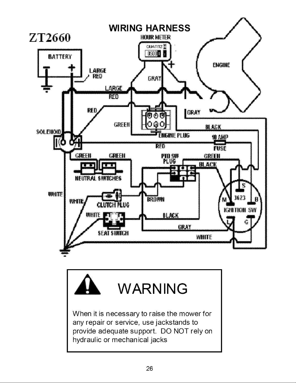
WIRING HARNESS
I
WARNING
When it is necessary to raise the mower for
any repair or service, use jackstands to
provide adequate support. DO NOT rely on
hydraulic or mechanical jacks
26
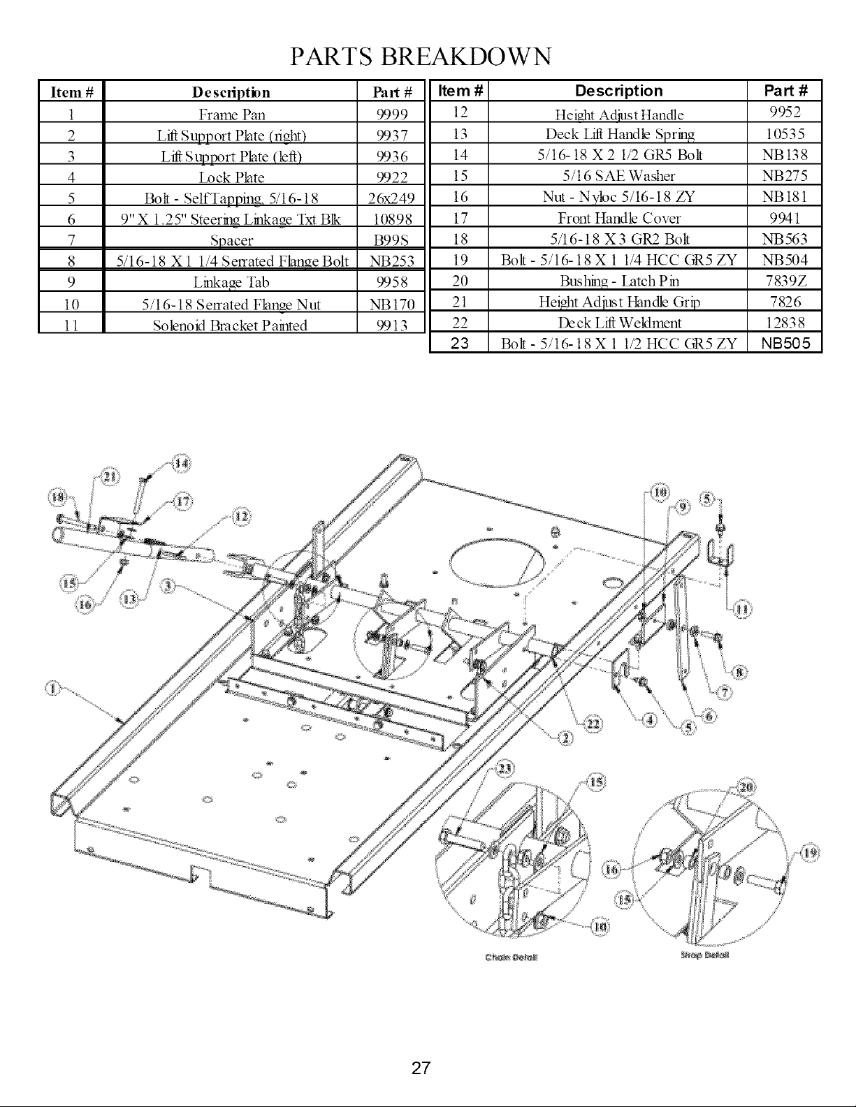
PARTS BREAKDOWN
Item #
1
2
3
4
5
6
7
8
9
10
11
Description
Frame Pan
Lift Support Plate (right)
L_ Suptx_rt Plate (left)
Lock Plate
Bolt - Self Tapping, 5/16-18
9"X 1.25" Steerh_g Li_Nage Txt Blk
Spacer
5/16-18 X 1 1/4 Serrated Flange Bolt
Li_age Tab
5/16-18 Serrated Flange Nut
Solenoid Bracket Painted
Part#
9999
9937
9936
9922
26x249
10898
B99S
NB253
9958
NB 170
9913
Item
12
13
14
15
16
17
18
19
20
21
22
23
Description
Heio.ht Adiust Handle
Deck Lift Handle Spring
5/16-18 X2 1/2 GR5 Bolt
5/16 SAE Washer
Nut - N¥1oc 5/16-18 ZY
From Handle Cover
5/16-18 X3 GR2 Bolt
Bolt - 5/16-18 X 1 1/4 HCC GR5 ZY
Bushing - Latch Pin
Height Adjust Handle Grip
De ck LN Weldmem
Bolt- 5/16-18 X 1 1/2 HCC GR5 ZY
Part#
9952
10535
NB138
NB275
NB181
9941
NB563
NB504
7839Z
7826
12838
NB505
27
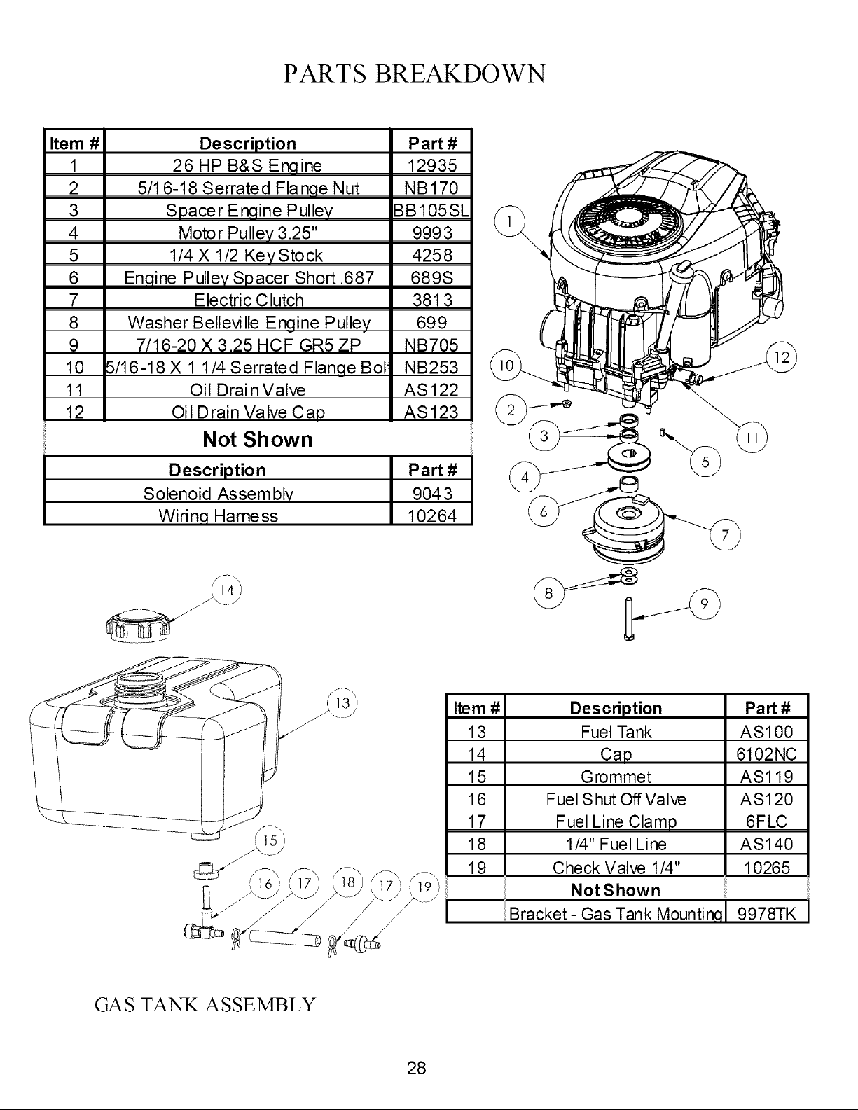
PARTS BREAKDOWN
Item #
1
2
3
4
5
6
7
8
9
10
11
12
Description
26 HP B&S Enqine
5/1 6-18 Serrated Flanqe Nut
Spacer Enqine Pulley
Motor Pulley 3.25"
1/4 X 1/2 KeyStock
Enqine Pulley Spacer Short .687
Electric Clutch
Washer Bellevi lie Engine Pulley
7/16-20 X 3.25 HCF GR5 ZP
5/16-18 X 1 1/4 Serrated Flange Bol
Oil Drai n Valve
Oil Drain Valve Cap
Not Shown
Part#
12935
NB170
BB105SL
9993
4258
689S
381 3
699
NB705
NB253
AS 122
AS123
Description
Solenoid Assembly
Wirinq Harness
Part #
9043
10264
I
j J"
Item #
13
14
15
16
17
18
19
Description
Fuel Tank
Cap
Grommet
Fuel S hut Off Valve
Fuel Line Clamp
1/4" Fuel Line
Check Valve 1/4"
NotShown
Bracket- Gas Tank Mountinq
Part #
AS100
6102NC
ASl19
AS120
6FLC
AS140
10265
9978TK
GAS TANK ASSEMBLY
28
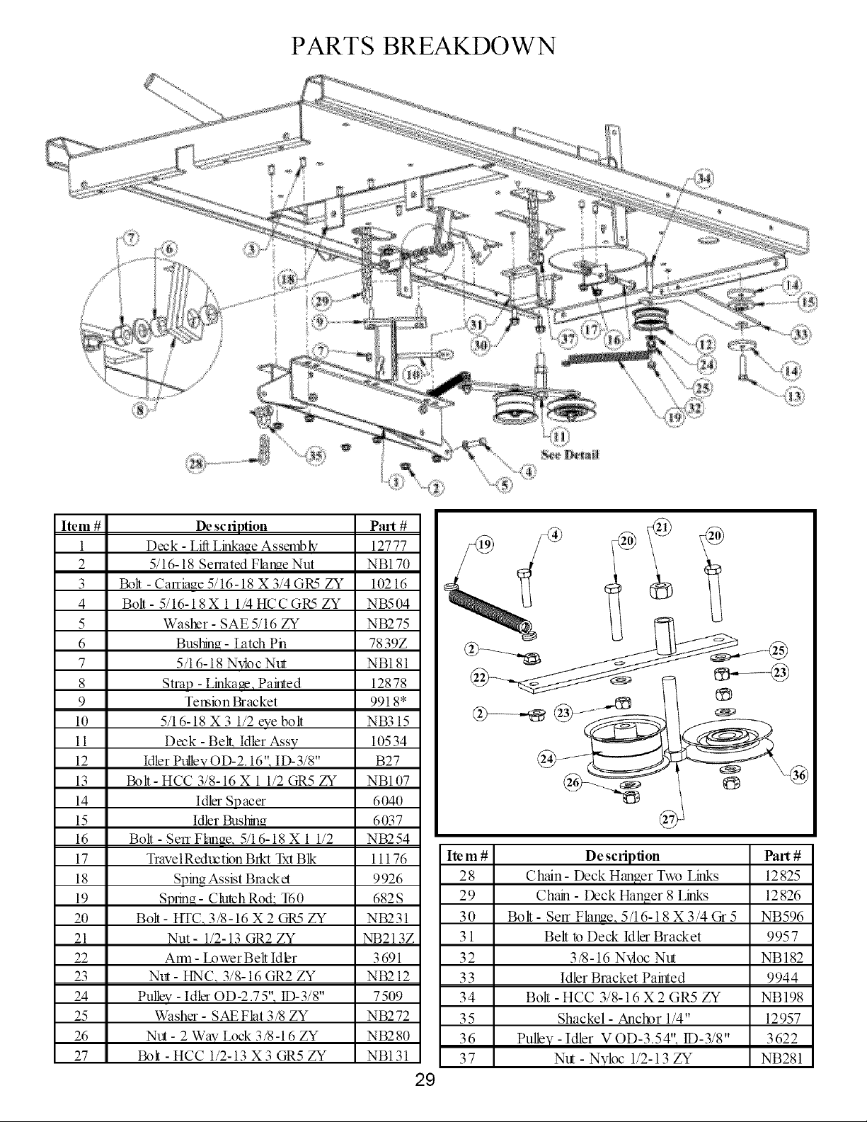
PARTS BREAKDOWN
Item #
1
2
3
4
5
6
7
8
9
10
11
12
13
14
15
16
17
18
19
20
21
22
23
24
25
26
27
De scfiption Part #
Deck - Lift Linkaue Assembly 12777
5/16-18 Senated Flame Nut NB170
Bolt - Cania_e 5/16-18 X 3/4 GR5 ZY 10216
Bolt- 5/16-18X 1 1/4 HCC GR5 ZY NB504
Washer- SAE 5/16 ZY NB275
Buskm_ - Latch Pn 7839Z
5/16-18 Nvloc Nut NB181
Strap - Linkage, Paiuted 12878
Temion Bracket 9918*
5/16-18 X 3 1/2 eve bolt NB3 15
Deck - Bell, Idler Assv 10534
Idler Pullev OD-2.16", ID-3/8" B27
Bolt- HCC 3/8-16 X 1 1/2 GR5 ZY NB107
Idler Spacer 6040
Idler Buskm_ 6037
Bolt - Sen Fkmae, 5/16-18 X 1 1/2 NB254
TravelReduction Brkt Txt Blk 11176
Sping Assist Bracket 9926
Sp_ina- Clutch Rod: T60 682S
Bolt- HTC, 3/8-16 X 2 GR5 ZY NB231
Nut - 1/2-13 GR2 ZY NB213Z
A_m - Lower Belt Idler 3 691
Nut - HNC, 3/8-16 GR2 ZY NB212
Pullev- Idler OD-2.75", 1D-3/8" 7509
Washer - SAE Flat 3/8 ZY NB272
Nut - 2 Wav Lock 3/8-16 ZY NB280
Bolt - HCC 1/2-13 X 3 GR5 ZY NB131
29
Item#
28
29
30
31
32
33
34
35
36
37
De scription
Chain - Deck Hanger Two Links
Chain - Deck Hanger 8 Links
Bolt - Serf FlamQ 5/16-18 X 3/4 Gr 5
Belt k_Deck Idler Bracket
3/8-16 Nyloc Nut
Idler Bracket Painted
Bolt - HCC 3/8-16 X 2 GR5 ZY
Shackel - Anctx_r 1/4"
PuNy - Idler V OD-3.54"q 1I)-3/8"
Nut - Nyloc 1/2-13 ZY
Part#
12825
12826
NB596
9957
NB 182
9944
NB 198
12957
3622
NB281
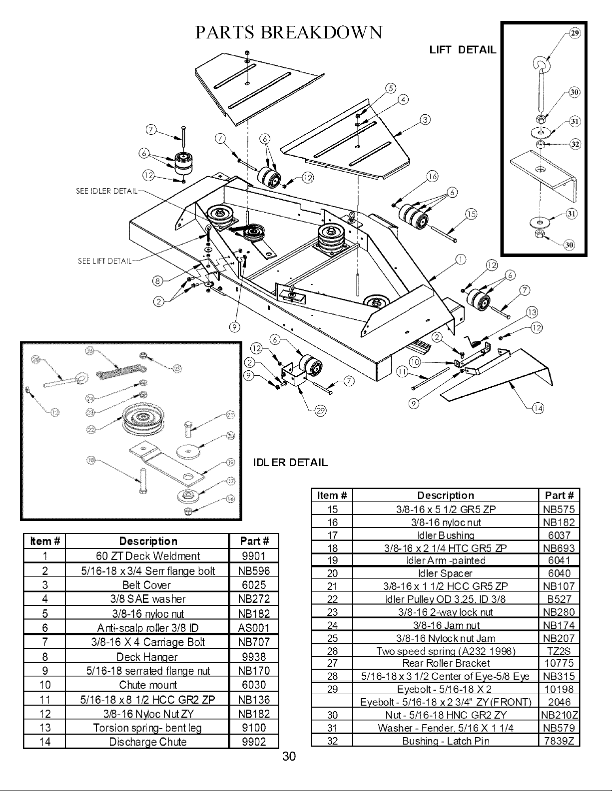
PARTS BREAKDOWN
LIFT DETAIL
SEEIDLER
SEE LIFT DETAIL
IDL ER DETAIL
Item #
I
2
3
4
5
6
7
8
9
10
11
12
13
14
Descriptio n
60 ZT Deck Weldment
5/16-18 x 3/4 Sen" flange bolt
Belt Cover
3/8 SAE washer
3/8-16 nytoc nut
Anti-scalp roller 3/8 ID
3/8-16 X 4 Carriage Bolt
Deck Han¢l,er
5/16-18 serrated flange nut
Chute mount
5/16-18 x8 1/2 HCC GR2 ZP
3/8-16 Ngoc NutZY
Torsion spring- bent leg
Discharge Chute
Part #
9901
NB596
6025
NB272
NB182
AS001
NB707
9938
NB170
6030
NB136
NB182
9100
9902
Item
15
16
17
18
19
20
21
22
23
24
25
26
27
28
29
3O
31
32
30
Description Part #
3/8-16 x 5 1/2 GR5 ZP NB575
3/8-16 nyloc nut NB182
Idler B ushi n,q 6037
3/8-16 x2 1/4 HTC GR5 ZP NB693
ldlerArm -painted 6041
Idler Spacer 6040
3/8-16 x 1 1/2 HCC GR5ZP NB107
Idler Pullev OD 3.25, ID 3/8 B527
3/8-16 2-way lock nut NB280
3/8-16 Jam nut NB174
3/8-16 Nylock nut Jam NB207
Two speed sprin,q (A232 1998) TZ2S
Rear Roller Bracket 10775
5/16-18 x 3 1/2 Center of Eye-5/8 Eye NB315
Eyebolt - 5/16-18 X 2 10198
Evebolt- 5/16-18 x2 3/4" ZY(FRONT) 2046
Nut - 5/16-18 HNC GR2 ZY NB210Z
Washer - Fender, 5/16 X 1 1/4 NB579
Bushin.q- Latch Pin 7839Z
I)
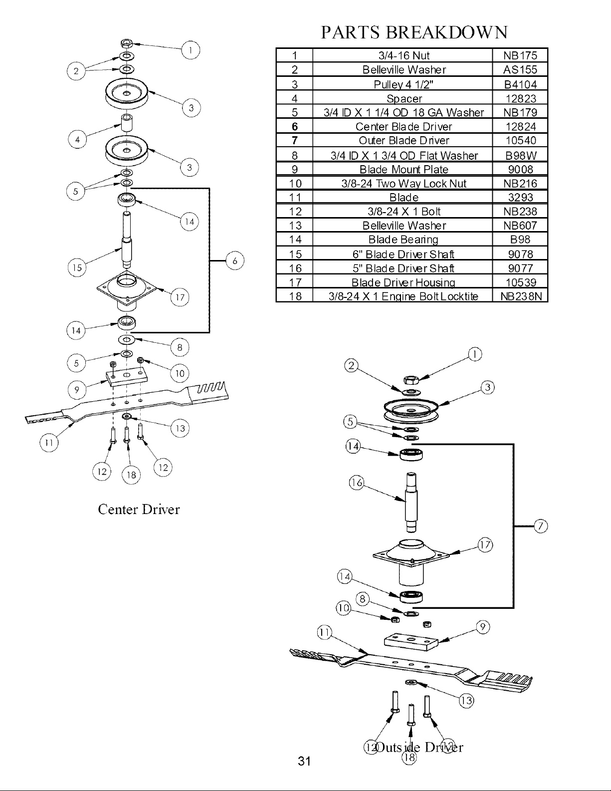
Center Driver
1
2
3
4
5
6
7
8
9
10
11
12
13
14
15
16
17
18
PARTS BREAKDOWN
3/4-16 Nut NB175
Bellevilte Washer AS155
Pulley 4 1/2" B4104
Spacer 12823
3/4 ID X 1 1/40D 18 GA Washer NB179
Center Blade Driver 12824
Outer Blade Driver 10540
3/4 ID X 1 3/40D Flat Washer B98W
Blade Mount Plate 9008
3/8-24 Two Way Lock Nut NB216
Blade 3293
3/8-24 X 1 Bolt NB238
Belteville Washer NB607
Blade Bearing B98
6" Blade Driver Shaft 9078
5" Blade Driver Shaft 9077
Blade Driver Housinq 10539
3/8-24 X 1 En.qine Bolt Locktite NB238N
31 21e D_r
PARTS BREAKDOWN
/
Item #
1
2
3
4
5
6
7
8
9
10
11
12
13
14
15
16
17
18
19
20
21
22
23
24
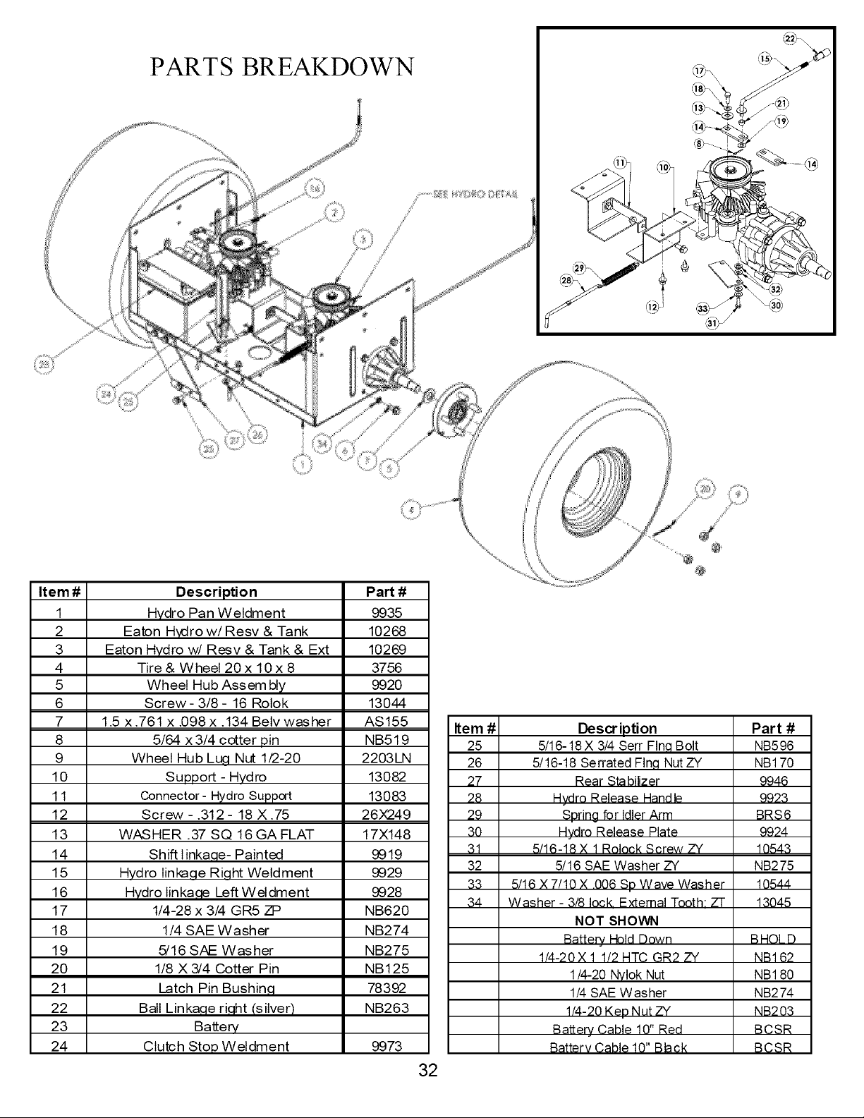
Descriptio n
Hydro Pan Weldment
Eaton H_ro w/Resv & Tank
Eaton Hydro w/Resv & Tank & Ext
Tire & Wheel 20 x 10 x 8
Wheel Hub Assembl¥
Screw- 3/8 - 16 Rolok
1.5 x .761 x .098 x .134 Betv washer
5/64 x 3/4 cotter pin
Wheel Hub Lu¢!,Nut 1/2-20
Support - Hydro
Connector- Hydro Support
Screw - .312- 18 X .75
WASHER .37 SQ 16 GA FLAT
Shift tinka,qe- Painted
Hydro linkage Right Weldment
Hydro Iinka,qe Left Weldment
1/4-28 x 3/4 GR5 ZP
1/4 SAE Washer
5/16 SAE Washer
1/8 X 3/4 Cotter Pin
Latch Pin Bushin,q
Bali Linka,qe ri,qht (silver)
Battery
Clutch Stop Weldment
Part #
9935
10268
10269
3756
9920
13044
AS155
NB519
2203LN
13082
13083
26X249
17X148
9919
9929
9928
NB620
NB274
NB275
NB125
78392
NB263
9973
Item #
25
26
27
28
29
30
31
32
33
34
32
Des cr ipti on
5/16-18X 3/4 Serr FIn,qBolt
5/16-18 Serrated FIn,qNut ZY
Rear Stabilzer
Hvdro Release Handle
SDrina for Idler Arm
Hvdro Release Plate
5/16-18 X 1 Rolock Screw ZY
5/16 SAE Washer ZY
5/16 X 7/10 X 006 Sn Wave Washer
Washer - 3/8 lock External Tooth: ZT
NOT SHOWN
Batterv Hold Down
1/4-20X 1 1/2 HTC GR2 ZY
1/4-20 Nylok Nut
1/4 SAE Washer
1/4-20 KeD Nut ZY
Batterv Cable 10" Red
Batterv Cable 10" Black
Part #
NB596
NB170
9946
9923
BRS6
9924
10543
NB275
10544
13045
BHOLD
NB1 62
NB1 80
NB274
NB203
BCSR
BCSR
PARTS BREAKDOWN
SEE
@
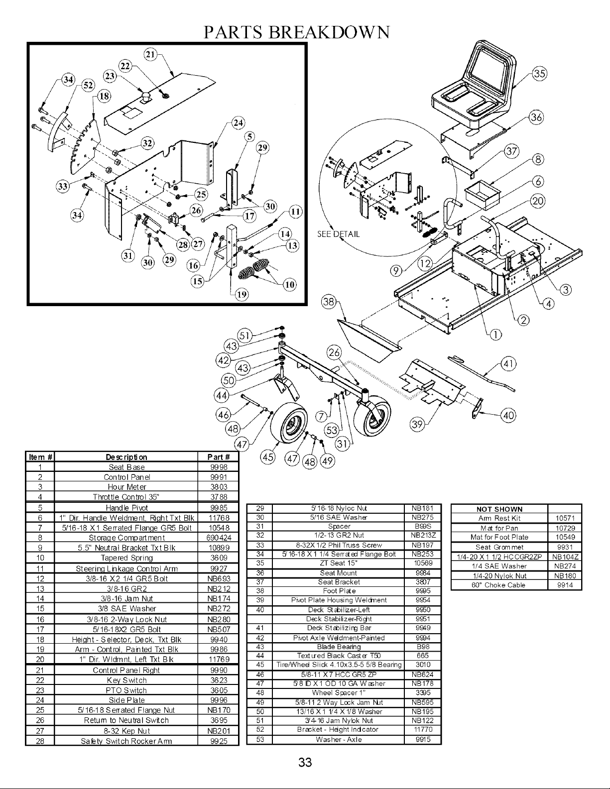
Item #
1
2
3
4
5
6
7
8
9
10
11
12
13
14
15
16
17
18
19
2O
21
22
23
24
25
26
27
28
Description Part #
Seat Base 99 98
Con trol Pan et 99 91
Hour Meter 3803
Throttle Control 35" 3788
Hand le Pivot 99 85
1" Dir. Handle Weldment, Ri,qht Txt BIk 11768
5/16-18 X1 Serrated Flan,qe GR5 Bolt 10548
St ora,qe Comp art men t 690424
5.5" Neutral Bracket Txt Btk 10899
Tapered Spring 3609
St eerinq L inka,qe Con trot Arm 99 27
3/8-16 X2 1/4 GR5 Bolt NB693
3/8-16 GR2 NB212
3/8-16 Jam Nut NB1 74
3/8 SA E Was her NB272
3/8-16 2-Way Lock Nut NB280
5/16-1 8X2 GR5 Bolt NB507
Hei,qht- Selector, Deck, Txt BIk 9940
Arm - Control, Painted Txt BIk 9986
1" Dir. Wtdmnt TLeft Txt BIk 11769
Control Panel Ri,qht 9990
Key Switch 3623
PTO Switch 3605
Side Plate 9996
5/16-18 Serrated Ftan,qe Nut NB1 70
Return to Neutral Switch 3695
8-32 Kep Nut NB201
Safety Switch RockerArm 9925
29 5/16-18 Nyloc Nut NB181
30 5/16 SAE Washer NB275
31 Spacer B99S
32 I/2-13 GR2 Nut NB213Z
33 8-32X 1/2 Phil Truss Screw NB197
34 5/16-18 X 1 1/4 Serrated Flange Bot_ NB253
35 ZT Seat 15" 10569
36 Seat Mount 9984
37 Seat Bracket 3807
38 Foot Plate 9995
39 Pivot Plate Housing Weldment 9954
40 Deck Sl goilizer-Left 9950
Dock Stabilizer-Ri_t 9951
41 Deck St abilizi_j Bar 9949
42 Pivot Axle Weldment-Painted 9994
43 Blade Beadng B98
44 Textured Black Caster T,50 665
45 Tire/Wheel Slick 4.10x3.5-5 5/8 Bearing 3010
46 5/8-11 X7 HCC GR5 ZP NB624
47 ,5/8 ID X 1 ©D 10 GA Washer NB178
48 Wheel Spacer 1" 3385
49 5/8-11 2 Way Lock Jam NJt NB595
50 13/16 X 1 1/4 X 1/8 Washer NB195
51 3'4-16 Jam Nybk Nut NB122
52 Bracket - Height tndcator 11770
53 Washer- Axle 9915
NOT SHOWN
Arm Rest Kit 10571
Mat for Pan 10729
Mat for Foot Plate 10549
Seat Gram met 9931
I/4-20 X 1 1/2 HCCGR2ZP NBI04Z
I/4 SAE Washer NB274
1/4-20 Nylok Nut NB180
60" Choke Cable 9914
33
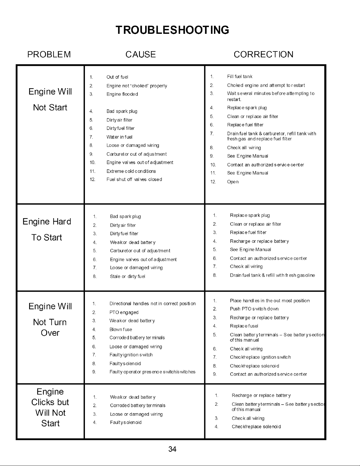
TROUBLESHOOTING
PROBLEM CAUSE CORRECTION
Engine Will
Not Start
Engine Hard
To Start
Engine Will
Not Turn
Over
Engine
Clicks but
Will Not
Start
1.
2.
3.
4.
5.
6.
7.
8.
Out of fuel
Engine not "choked" properly
Engine flooded
Bad spark plug
Dirtyair filter
Dirtyfuel filter
Water in fuel
Loose or damaged wiring
1.
2.
3.
4.
5.
6.
7.
Fill fuel tank
Choked engine and attempt to restart
Wait s evera! minutes before attempting to
restart.
Replace spark plug
Clean or repl ace air filter
Replace fuel filter
Drain fuel tank &carburetor, refill tank with
fresh gas and replace fuel filter
Check all wiring
9. Carburetor out of adjustment
10. Engine valves out of adjustment
11. Extreme cold con ditions
12. Fuel shut off valves closed
1.
2.
3.
4.
5.
6.
7.
8.
Bad spark plug
Dirtyair filter
Dirtyfuel filter
Weakor dead battery
Carburetor out of adjustment
Engine valves out of adjustment
Loose or damaged wiring
Stale or dirty fuel
Directional handles not in correct position
9. See Engine Manua!
10. Contact an authorized ser_icecenter
11. See Engine Manua!
12. Open
1.
2.
3.
4.
5.
6.
7.
8.
Replace spark plug
Clean or repl ace air filter
Replace fuel filter
Recharge or replace battery
See Engine Manual
Contact an authorized service center
Check all wiring
Drain fuel tank & refill with fresh gas el!he
1.
2.
Place handles in theout most position
Push PTO switch down
2.
3.
4.
5.
6.
7.
8.
PTO engaged
Weaker dead battery
Blown fuse
Corroded battery terminals
Loose or damaged wiring
Faultyignition switch
Faultys olenoid
3.
4.
5.
6.
7.
8.
Recharge or replace battery
Replace fusel
Clean batteryterminals - See batterysection
of t his m an ual
Check all wiring
Check/replace ignition switch
Check/replace solenoid
1.
2.
3.
4.
Faulty operator presence switch/switches
Weakor dead battery
Cor rode d b att ery terminals
Loose or damaged wiring
FauItysoIenoid
1.
2.
3.
4.
Contact an authorized service center
Recharge or replace battery
Clean batter ytermin als - See batter y s ectio
of this manual
Check all wiring
C hec k/re place sole no! d
34
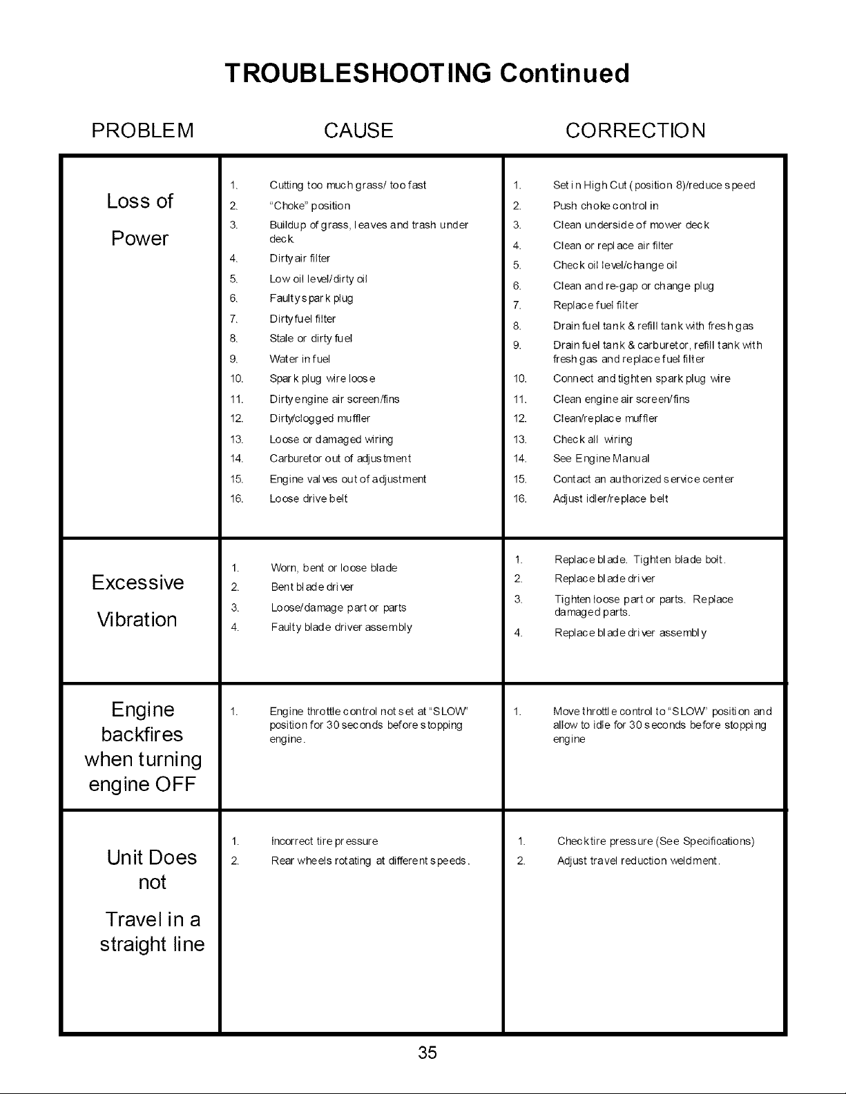
TROUBLESHOOTING Continued
PROBLEM CAUSE CORRECTIO N
Loss of
Power
Excessive
Vibration
Engine
backfires
when turning
engine OFF
Unit Does
not
Travel in a
straight line
1.
2.
3.
Cutting too much grass/too fast
"Choke" position
Buildup of grass, leaves and trash under
dec k.
4. Dirty air filter
5. Low oil level/dirty oil
6. Faultyspar k plug
7. Dirty fuel filter
8. Stale or dirty fuel
9. Water in fuel
10. Spar k plug wire loose
11. Dirtyengine air screen/fins
12. Dirty/cIogg ed muffler
13. Loose or damaged wiring
1.
2.
3.
4.
5.
6.
7.
8.
9.
10.
11.
12.
13.
Set i n High Cut ( position 8)/red uce s peed
Push choke control in
Clean undersideof mower deck
Clean or repl ace air filter
Chec k oil Ievellc ha nge oil
Clean and re-gap or change plug
Replace fuel filter
Drain fuel tank & refill tank with fresh gas
Drain fuel tank & carburetor, refill tank with
fresh gas and replace fuet filter
Connect and tighten spark plug wire
Clean engine air screen/fins
Clean/replace muffler
Check all wiring
14. Carburetor out of adjustment
15. Engine valves out of adjustment
16. Loose drive belt
1.
2.
3.
4.
1.
2.
Worn, bent or loose blade
Bent blade driver
Loose/damage part or parts
Faulty blade driver assembly
Eng ine thro ttte c on trol not s et at "S LOW'
position for 30 sec on ds before s to ppi ng
engine.
Incorrect tire pr essure
Rear wheels rotating at different speeds.
14. See Engine Manual
15. Contact an authorizedser_ce center
16. Adjust idler/replace belt
1.
2.
1.
2.
3.
Replace blade. Tighten blade bolt.
Replace blade dri ver
Tighten loose partor parts. Replace
damaged parts.
Replace blade driver assembly
Move t hrottl e control to "SLOWt' positi on and
allow to idle for 30 seconds before stopping
engine
Checktire pressure (See Specifications)
Adjust travel reduction weldment.
35

TROUBLESHOOTING Continued
PROBLEM CAUSE CORRECTIO N
Poor cut -
uneven
Battery will
not charge
Loss of drive
1.
2.
3.
4.
5.
1.
2.
3.
1.
2.
3.
Worn, bent or loose blade
Mower deck not level
Buildup of grass, leaves and trash under
dec k
Bent deck
Faulty Blade driver assembly
Bad battery
Poor cable connections
Faultys olenoid
Bypass linkages in the bypass position
Hydro belt worn, damaged, or broken
Idler spring loose or broken
1.
2.
3.
4.
5.
1.
2.
2.
3.
Replace blade. Tighten blade bolt
Level deck See sect! on i n this manua!
Clean undersideof mower deck
Replace deck
Replace bl ade dr! ver asse mbt y
Replace b att ery
Check/clean all connections. See section in
this manual
Replace soienoid
Make sure that the bypass linkages are i n
the drive or engaged position. Located at
the rear of the machine. Refer to decal on
the rear of the unit.
Replace Hydro belt.
Replace Idler spring
36
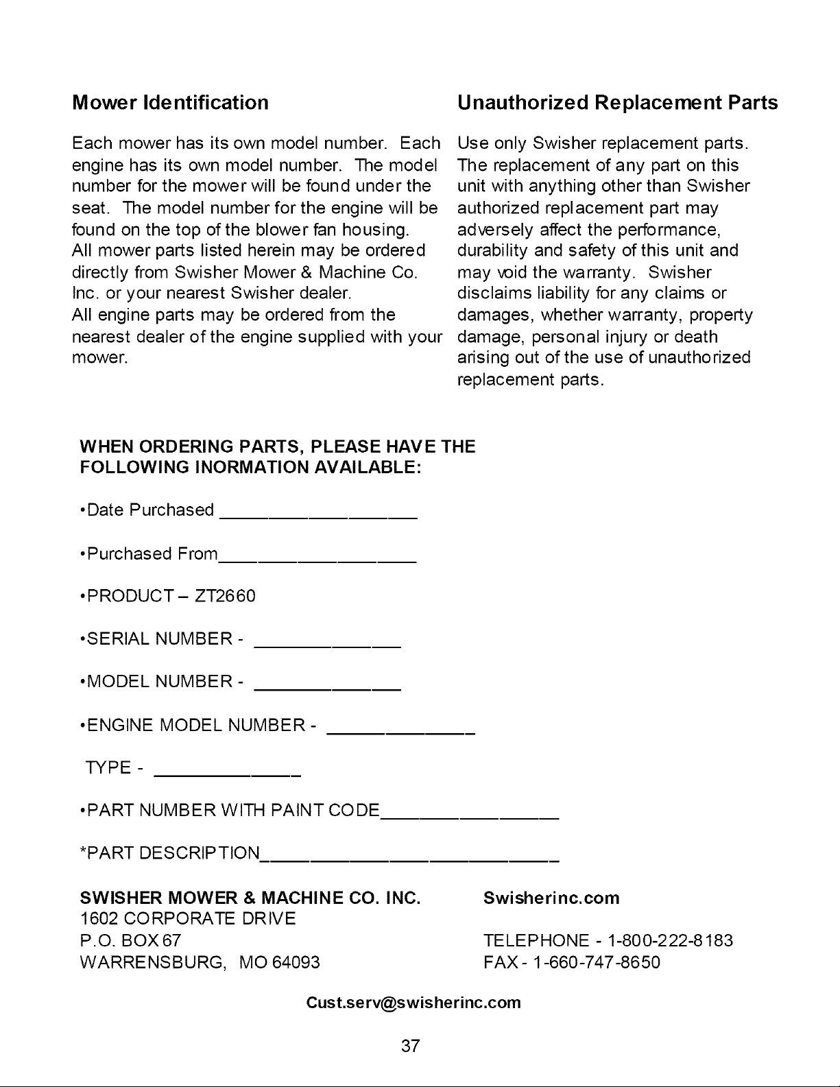
Mower Identification Unauthorized Replacement Parts
Each mower has its own model number. Each
engine has its own model number. The model
number for the mower will be found under the
seat. The model number for the engine will be
found on the top of the blower fan housing.
All mower parts listed herein may be ordered
directly from Swisher Mower & Machine Co.
Inc. or your nearest Swisher dealer.
All engine parts may be ordered from the
nearest dealer of the engine supplied with your
mower.
Use only Swisher replacement parts.
The replacement of any part on this
unit with anything other than Swisher
authorized replacement part may
adversely affect the performance,
durability and safety of this unit and
may void the warranty. Swisher
disclaims liability for any claims or
damages, whether warranty, property
damage, personal injury or death
arising out of the use of unauthorized
replacement parts.
WHEN ORDERING PARTS, PLEASE HAVE THE
FOLLOWING INORMATION AVAILABLE:
• Date Purchased
•Purchased From
• PRODUCT- ZT2660
• SERIAL NUMBER-
• MODEL NUMBER-
• ENGINE MODEL NUMBER-
TYPE -
• PART NUMBER WITH PAINT CODE
*PART DESCRIPTION
SWISHER MOWER & MACHINE CO. INC.
1602 CORPORATE DRIVE
P.O. BOX 67
WARRENSBURG, MO 64093
Swisherinc.com
TELEPHONE - 1-800-222-8183
FAX- 1-660-747-8650
37
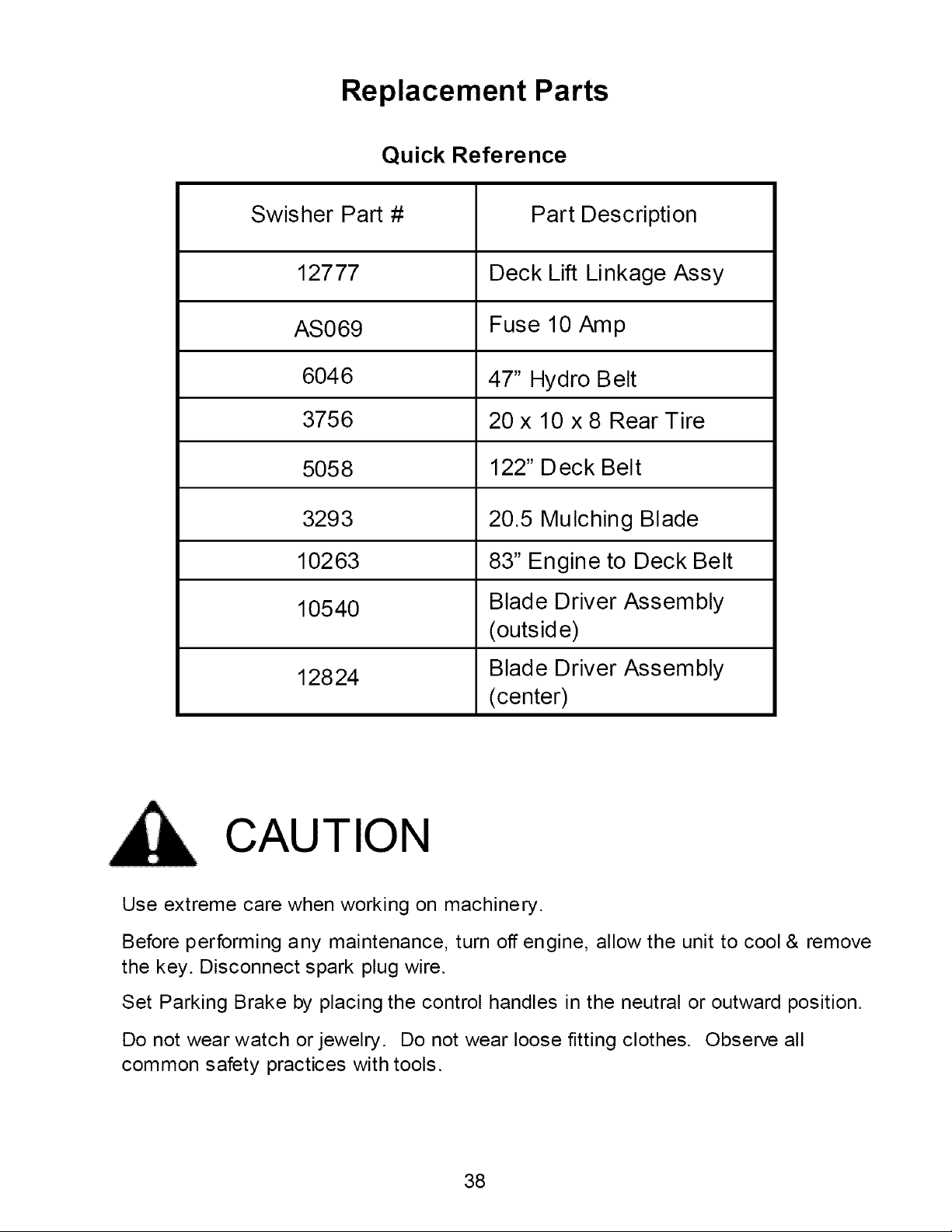
Replacement Parts
Quick Reference
Swisher Part # Part Description
12777 Deck Lift Linkage Assy
AS069 Fuse 10 Amp
6046 47" Hydro Belt
3756 20 x 10 x 8 Rear Tire
5058 122" Deck Belt
3293 20.5 Mulching Blade
10263 83" Engine to Deck Belt
10540 Blade Driver Assembly
(outside)
12824 Blade Driver Assembly
(center)
CAUTION
Use extreme care when working on machinery.
Before performing any maintenance, turn off engine, allow the unit to cool & remove
the key. Disconnect spark plug wire.
Set Parking Brake by placing the control handles in the neutral or outward position.
Do not wear watch or jewelry. Do not wear loose fitting clothes. Observe all
common safety practices with tools.
38

WARRANTY RIGHTS AND OBLIGATIONS
YOUR WARRANTY RIGHTS AND OBLIGATIONS: The California Air Resources Board and Swisher Mower, is pleased to
explain the evaporative emission control system (EECS) on your model year 2006 and laterSwisher Product. In California,
new Outdoor Power Equipment, must be designed, built and equipped to meet the State's stri ngent anti-smog standards.
Swisher Mower must warrant the EECS on your Power Equipment, for the period of time listed below provided there has been
no abuse, neglect, or improper maintenance. For model year 2006 the EECS on your mowerindudes the liquid fuel lines, fuel
line connectors, and fuel line damps. Where a warrantable condition exists, Swisher Mower will repair at no cost to you.
Expenses covered under warranty include diagnosis, parts, and labor.
MANUFACTURER'S WARRANTY COVERAGE: For a period of two years, anyevaporative emission-related part included in
the list of EECS parts for your mov,er is defective, the part will be repaired or replaced by Swisher Mower.
OWNER'S WARRANTY RESPONSIBILITIES: As the owner of this Power Equipment, you are responsible for performance of
the required maintenance listed in your owner's manual. Swisher Mower recommends that you retain all receipts covering
maintenance on your Power Equipment, but Swisher Mower cannot deny warranty solely for the lack of receipts. As the Power
Equipment owner, you should be aware that Swisher Mower, maydeny you warranty coverage if your Power Equipment, or a
covered part has failed due to abuse, neglect, orimproper maintenance, unapproved modifications, or the use of parts not
made or approved bythe equipment manufacturer. You are responsible forpresenting your Power Equipment to an authorized
Swisher Service centeras soon as the problem exists. Warranty repairs should be completed in a reasonable amount of time,
not to exceed 30 days. tf you have a question regarding your warranty rights and responsibilities, you should contact the
Swisher Mower Service representative at 1-800-222-8183.
WARRANTY COMMENCEMENT DATE: The warranty period begins on the date the Power Equipment Is purchased.
LENGTH OF COVERAGE: This warranty shall be fora period of two (2) years from the initial date of purchase.
WHAT IS COVERED: Warranted parts include the Liquid fuel line, fuel line connectors, and fuel line clamps.
REPAIR OR REPLACEMENT OF PARTS: Repair or replacement of any evaporative warranted part will be perfon'ned at no
charge to the owner at an authorized SwisherMower Service Center. tf you have a question regarding your warranty rights and
responsibilities, you should contact your nearest authorized service center or call the Swisher Mower Service representative at
1-800-222-8183.
WARRANTY PERIOD: Any warranted part is not scheduled for replacement as required maintenance, or which is scheduled
only for regular inspection to the effect of "repairor replace as necessary" shall be warranted for two (2) years. Any warranted
part that is scheduled for replacement as required maintenance shall be warranted for the period of time up to the first
scheduled replacement point for that part.
DIAGNOSIS: The owner shall not be charged for diagnostic labor that leads to the determi nation that a warranted part is
defective if the diagnosticworkis performed atan authorized Swisher Service Center.
CONSEQUENTIAL DAMAGE: Swisher Mower, may be liable for damages to other engine or equipment components caused
by the failure of a warranted part still under warranty.
WHAT IS NOT COVERED: All failures caused byabuse, neglect, or improper maintenance is not covered.
ADD-ON OR MODIFIED PARTS: The use of add-on or modified parts may be grounds fordisallowing a warranty claim.
Swisher Moweris not liable to cover failures of warranted parts caused bythe use of an add-on or modified part.
HOW TO FILE A CLAIM: If you have a question regarding your warranty rights and responsibilities, you should contact your
nearest authorized service centeror call Swisher Mower Service representative at 1-800-222-8183.
39
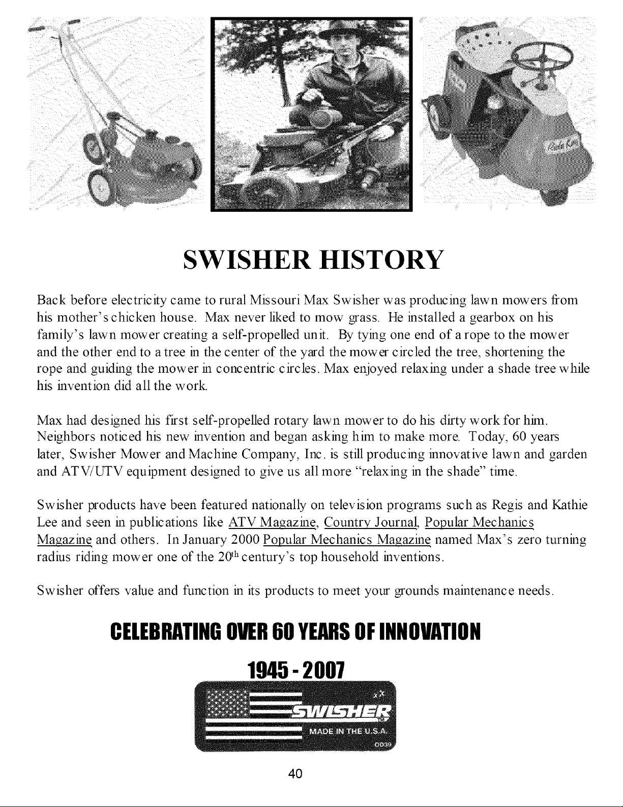
SWISHER HISTORY
Back before electricity came to rural Missouri Max Swisher was producing lawn mowers from
his mother's chicken house. Max never liked to mow grass. He installed a gearbox on his
family's lawn mower creating a self-propelled unit. By tying one end of arope to the mower
and the other end to a tree in the center of the yard the mower circled the tree, shortening the
rope and guiding the mower in concentric circles. Max enjoyed relaxing under a shade tree while
his invention did all the work.
Max had designed his first self-propelled rotary lawn mower to do his dirty work for hhn.
Neighbors noticed his new invention and began asking hhn to make more. Today, 60 years
later, Swisher Mower and Machine Company, Inc. is still producing innovative lawn and garden
and ATV/L_V equipment designed to give us all more "relaxing in the shade" thne.
Swisher products have been featured nationally on television programs such as Regis and Kathie
Lee and seen in publications like ATV Magazin e, Country Journa!, Popular Mechanics
Magazin e and others. In January 2000 Popular Mechanics Magazin e named Max's zero turning
radius riding mower one of the 20 th century's top household inventions.
Swisher offers value and function in its products to meet your grounds maintenance needs.
CELEBRATINGOVER60 YEARSOFINNOVATION
1945- 2007
4O