27 HP- 66" CUT
CELEBRATIHGOVER60YEARSOFINNOVATION
1945-2008
I 1602 CORPORATE DRIVE, P.O. BOX 67, WARRENSBURG, MISSOURI 64093 /
"N
PHONE 660-747-8183 FAX 660-747-8650 Made In The
1
Manufacturing quality lawn care equipment since 1945 USA J
14689
Rev,,08-221
OWNER'S MANUAL
STARTING SERIAL # L108-193001
LiMiTED WARRANTY
The manufacturer's warranty to the original consumer purchaser is: This product is free
from defects in materials and workmanship for a period of two (2) years from the date of
purchase by the original consumer purchaser° We will repair or replace, at our discretion,
parts found to be defective due to materials or workmanship. This warranb/is subject to
the following limitations and exclusions:
1) Engine Warranty Al! engines utilized on our products have a separate warranty
extended to them by the individual engine manufacturer. Any
engine service difficulty is the responsibility of the engine
manufacturer and in no way is Swisher Mower Co., Inc,. or its
agents responsible for the engine warranty,. The Briggs &
Stratton Engine Service Hot-Line is 1-800-233-3723. The
Tecumseh Engine Service Hot-Line is 1-800-558-5402.
2) Commercial Use This product is not intended for commercial use and
carries no commercial warranty.
3) Limitation
4) Exclusions
This warranty applies only to products which have been
properly assembled, adjusted, and operated in accordance
with the instructions contained within this manual. This
warranty does not apply to any product of Swisher Mower
Coo, Inc., that has been subject to alteration, misuse,abuse,
improper assembly or installation, shipping damage, or to
normal wear of the product°
Excluded from this warranty are normal wear, normal
adjustments, normal maintenance, and battery*(see
battery section_)
In the event you have a claim under this warranty, you must return the product to an
authorized service dealer. All transportation charges, damage, or loss incurred during
transportation of parts submitted for replacement or repair under this warranty shall be
borne by the purchaser. Should you have any questions concerning this warranty, please
contact us toll-free at 1-800-222-8183. The model number, serial number, date of
purchase, and the name of the authorized Swisher dealer from whom you purchased the
mower wilt be needed before any warranty claim can be processed.
THIS WARRANTY DOES NOT APPLY TO ANY INCIDENTAL OR CONSEQUENTIAL
DAMAGES AND ANY IMPLIED WARRANTIES ARE LIMITED TO THE SAME TIME
PERIODS STATED HEREIN FOR ALL EXPRESSED WARRANTIES. Some states do not
allow the limitation of consequential damages or limitations on how long an implied
warranty may last, so the above limitations or exclusions may not apply to you. This
warranty gives you specific legal rights and you may have other rights, which vary from
state-to-state. This is a limited warranty as defined by the Magnuson-Moss Act of 1975.
, _ 'CONTENTS
LIMITED WARRANTY .......... 2 ' OPERATION ....................... 13
i ii ....... ii i iii
INTRODUCTION. ..:4 :_Features. 13
:Before Operating ................ :4 _ Grass Height of Cut ............. ::16
..............Uncrating & Assembly.o..... °°. 5 ........................................Controls .? ..................
SYMBOLS & DECALS ........ 1:6 SERVICE & ADJUSTMENTS18
,i+i+i+ii++i.........iii.LII+IIIIIIIIi_iiiiii,.iiiiiiiiiiiiii/iiiii+iiiii+iiii iii i IIIIIIIIIIZI iiiiiiiiiiiiiiiiiiiiiii iiiiiiiiiiiiiii iiiiiiiiiiiiii ii ii_
SAFETY INSTRUCTIONS. ,7 Adjusting Deck Height.. .: 18 +
General use and safety rules.. 7 _,Deck Level ......................... _18
iiiiiii iii i+iiiiiiiiiiiii-i+i+ii+iii+i+iiiii+i+iiiIYliiiiiiiiiiiliiiii iii,iiiilYl iiiiiiiiiiiiiiiiiiiii ii iiiiiiiii ii
..............................!........................................+......................................!..................................+............................................................................................................................................!...............................................!...................................................................................
.............................S!0.Pe, operation?. ?,.r.:r.,r.: r..+,::8 Deck Belt Replacement ......... :19
CUSTOMER i i
........................... : , !Hydro Belt Replacement ......... :20
RESPONSIBILITY .... ilO + +_ ::.......
...........................................................................................................................+-"-. ++' +".+"._........................................................................................................................................................................................................................................................................................................
+ + + + +Seat Adjustment, 21
............................ ..................................i..................................................................................................................................................................
WIRING SCHEMATIC. 22
i ==_===m=_
Tires ..................................... 10
PARTS BREAKDOWN ......... 23
....................................Bia e ...............................................................................................................................................................................................
+ + iMOWER IDENTIFICATION... 36
.................................v:b+eiiSiiiil, ..................................i.........................i.........................................................................i.................................................................................
................ + ............ ............ + ................................. SWISHER HISTORY ............. 39
............................i,Tra ns.p0rt! ng Safety:.... :.__..:.._:.:i++!.!...............;i..............................................................................................................................................................
i i }
........................i...............................................................................................................................................................}.......................................................................................................................................................+......................................................................................................
SPECIFICATIONS. 11 . i
............................................................................................................."__'+_.'+_+,_+'__,++?++?+"+.+,+_?.+_'.+'++"............................i.......................................................................................................................................................................................................................................
+ +
............................................................... ........................................................................................ :............................... :..................... +......................................................................... +............................................................................................................... i ........................................
+ P 3 +
Maintenance ..........................................+12 + + : : +

iNTRODUCTiON
Congratulations
Thank you for purchasing a Swisher Zero Turn mower. This machine is built for the
greatest efficiency and rapid mowing of large areas. Conveniently located controls and
dual commercial grade hydrostatic transmissions regulated by steering levers, contribute to
the machine's performance°
This manual is a valuable document. Following the instructions for use, ser'¢ice,
maintenance, etc. can greatly increase the life-span of your machine.
General
In this operator's manual, left and right, backward and forward are used in relation to the
normal operators position.
NOTE:
Read Before Operating
if you have never used a Zero Turn mower before, refer
to the Operation Controls section of this manual before
attempting to operate one for the first time.
This machine is constructed only for mowing grass on lawns and other free and even
ground without obstacles. This machine is not intended for commercial use. The
manufacturer's directions concerning operation, maintenance, and repairs must be
carefully followed.
This machine must only be operated, maintained, and repaired by persons that are
familiar with the machine's special characteristics and who are well versed in safety
instructions.,
Accident prevention regulations, other general safety regulations, occupational safety
rules, and traffic regulations must be followed without fail.
Unauthorized modifications to the design of the machine may absolve the manufacturer
from liability for any resulting personal injury or property damage°
> Read engine manufacturer's
operating and maintenance instructions.
> Read and observe all safety
instructions on your mower and in the
manual.
Check engine oil.
Check fuel caps to sure that they
are in place,,
Know how to set the parking brake.
Be sure mower blades are turned off-
PTO switch pushed down..
Know how to stop the engine - Turn key
to off
Know how to stop the unit - Return
control handles to neutral
4
INTRODUCTION
Uncrating & Assembly
TOOLS REQUIRED:
v" 2 - ½" Wrenches or ½" Socket with drive ratchet
•/ Tire pressure gauge
v" Nail bar or claw hammer
-/ Wire snips
To Remove The Mower From The Crate:
Dispose of top and side panels of the crate,
Remove loose parts and packing material.
Cut any banding or strapping that may be holding the mower to the crate.
Disengage spark plug wire and place where it cannot make a connection,.
Raise the mower deck to its highest position.
Install steering levers,, Remove the bolts from the control arms on the mower. Align
the holes in the lever with the holes in the control arms and attach with the bolts provided,_
Make sure both bolts on both handles are tight.
Disengage the parking brake by pushing the handles to their fully extended position°
Open the transmission valves at the rear of the unit by pulling the release rods and
locking them in place. SEE INSTRUCTION DECAL AT THE REAR OF THE UNIT.
Carefully push the mower off the crate to a safe and level area,,
Check engine oilo All engines are filled with oil and tested at the factory° Verify oil
level and add if necessary before starting engine. SEE ENGINE OWNER'S MANUAL
Check the battery, if the battery is put into service after the "month & year" of the
date on the battery, then it may need to be charged with a 12 volt charger for a minimum
of 1 hour, but no more than 2 hours at a rate of 6 to 10 amps.
> Attach battery cables to battery. Always attach the positive terminal first.
Close the transmission valves at the rear of the unit, SEE INSTRUCTION DECAL
AT THE REAR OF THE UNIT.
> Reconnect spark plug wire°
> Check tire pressure on all four wheels° REFER TO UNIT SPECIFICATIONS TABLE
5
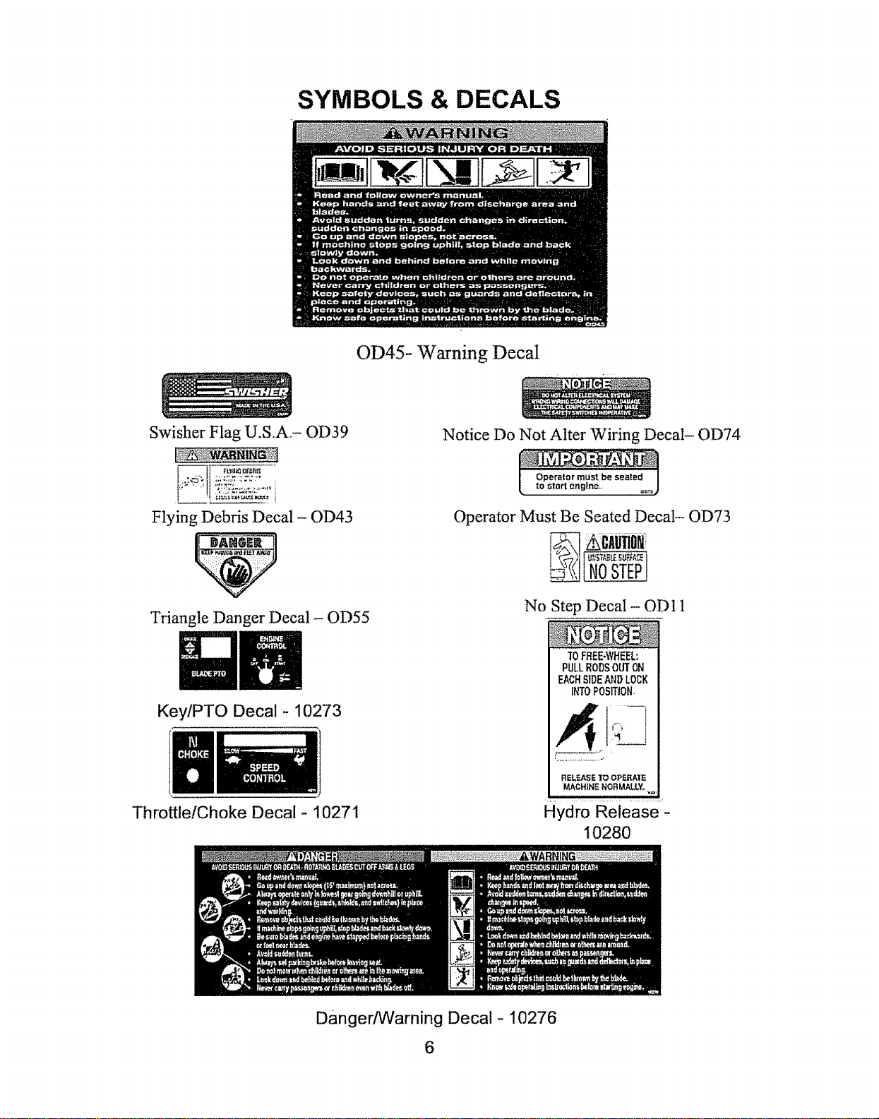
SYMBOLS & DECALS
OD45- Warning Decal
Swisher Flag U.S.A- OD39
Flying Debris Decal - OD43
Triangle Danger Decal - OD55
Key/PTO Decal - 10273
Throttle/Choke Decal- 1027I
Notice Do Not Alter Wiring Decal- OD74
Operator must be seated
to start engine,,
Operator Must Be Seated Decal- OD73
No Step Decal - OD 11
TOFFIEE.\VHEEL:
PULLRODSOUTON
EACHSIDEAND LOCK
INT0POSITION,
E
RELF.J_E TO O:P_I{_
MACHINE NORMALLY°
Danger/Warning Decal- 10276
10280
6
SAFETY INSTRUCTIONS
These instructions are for your safety. Read them carefully.
General Use
> Read all instructions in this operator's manual and on the
machine before starting iL Ensure that you understand them and
then abide by them.
>Learn how to use the machine and its controls safely and learn
how to stop quickly° Also learn to recognize the safety decals,
> Only allow the machine to be used by adults who are familiar
with its use.,
> Make sure nobody else is in the area of the machine when you
start the engine, engage the drive, or run the machine.
>Stop the machine if someone enters the work area.
>Clear the area of objects such as stones, toys, steel wire, etc..
that may become caught in the blades and thrown out.
Do Not Use this machine without the Discharge
Chute in place.
> Stop the engine and disconnect the spark ptug before cleaning
the discharge deck..
MoTEl.........
If you have never used a Zero Turn
mower before, refer to the Operation
Controls section of this manual before
attempting to operate one for the first
time.
> Never take passengers., The machine is only intended for use
by one person.
> Always look around before and during reversing maneuvers..
> Slow down before tuming_
> Shut down the mower deck when not mowing..
> Be careful when rounding fixed objects, so that the blades do
not hit them..
Only operate the machine in daylight or other well-lit
conditions,.
> Keep the machine a safe distance from holes or other
irregularities in the ground,
Never use the machine if you are tired, if you have consumed
alcohol, or if you are taking other drugs or medications that can
affect your vision, judgment, or coordination_
Beware of trafficwhen workingnear or crossing a road_
Never leave the machine unsupervised with the engine running..
Always shut down the blades, engage the parking brake, stop the
engine, and remove the ignition key before leaving the machine.
> Never allow children or other persons not trained in the use of
the machine to use or service it, Local laws may regulate the age
of the user_
Make sure that you have first aid equipment close at hand
when using the machine°
> Never use the machine when barefoot.. Aiways wear protective
shoes or boots,,
7
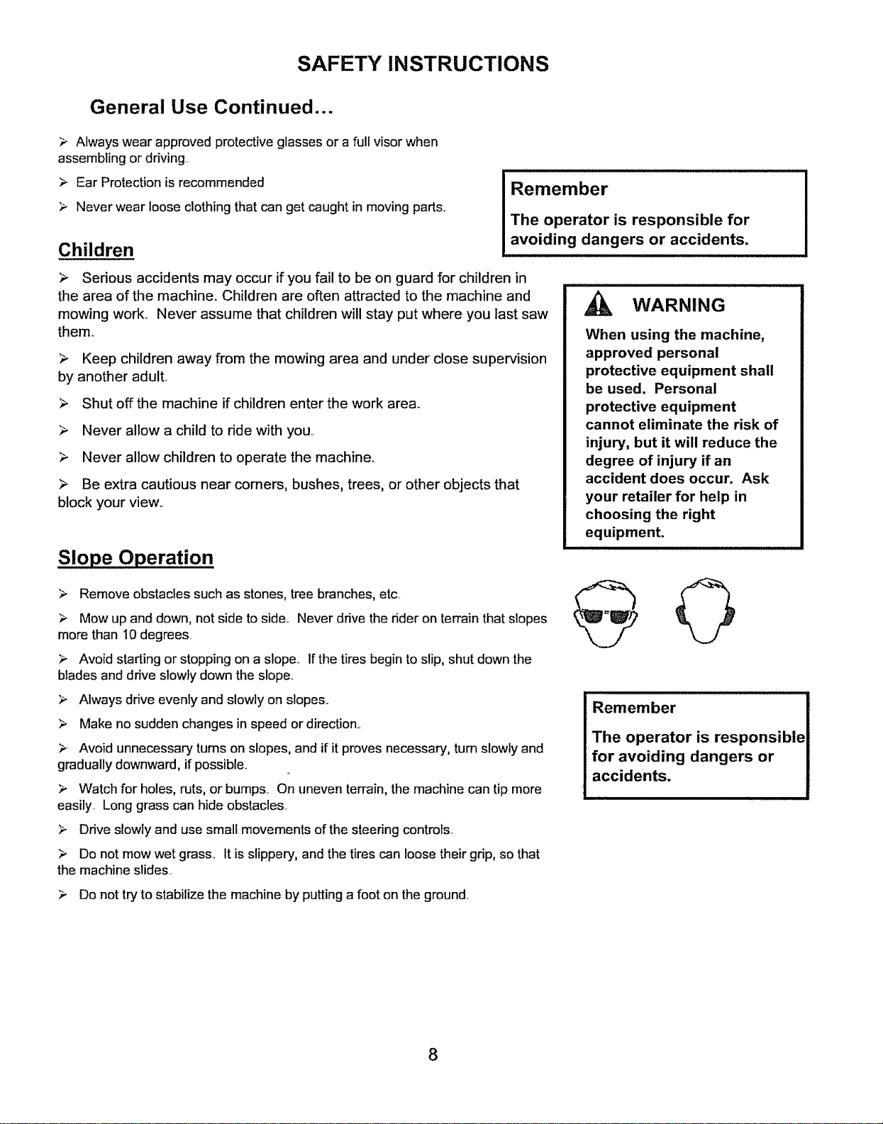
SAFETY INSTRUCTIONS
General Use Continued...
> Always wear approved protective glasses or a full visor when
assembling or driving.
> Ear Protection is recommended
>, Never wear loose clothing that can get caught in moving parts,.
Children
Remember
The operator is responsible for
avoiding dangers or accidents.
> Sedous accidents may occur if you fail to be on guard for children in
the area of the machine. Children are often attracted to the machine and
mowing work.. Never assume that children will stay put where you last saw
them.
> Keep children away from the mowing area and under close supervision
by another adult.
> Shut off the machine if children enter the work are&
> Never allow a child to ride with you,
> Never allow children to operate the machine,,
> Be extra cautious near comers, bushes, trees, or other objects that
block your view°
Slope Operation
> Remove obstacles such as stones, tree branches, etc.
> Mow up and down, not side to side.. Never drive the r_der on terrain that slopes
more than 10 degrees.
_,, Avoid starting or stopping on a slope., If the tires begin to slip, shut down the
blades and drive slowly down the slope..
> Always drive evenly and slowly on slopes.
> Make no sudden changes in speed or direction.,
>. Avoid unnecessary turns on slopes, and if it proves necessary, turn slowly and
gradually downward, if possible.
> Watch for holes, ruts, or bump& On uneven terrain, the machine can tip more
easily.. Long grass can hide obstacles..
> Drive slowly and use small movements of the steering controls.,
> Do not mow wet grass.. It is slippery, and the tires can loose their gdp, so that
the machine slides..
_, WARNING
When using the machine,
approved personal
protective equipment shall
be used. Personal
protective equipment
cannot eliminate the risk of
injury, but it will reduce the
degree of injury if an
accident does occur. Ask
your retailer for help in
choosing the right
equipment.
i
i i it
Remember
The operator is responsible
for avoiding dangers or
accidents.
> Do not try to stabilize the machine by putting a foot on the ground.
8
MOWING SAFETY
.WARNING - Petrol is highly flammable,,
- store fuel in containers specifically designed for this purpose;
- refuel outdoors only and do not smoke while refueling;
- add fuel before starting the engine, Never remove the cap of the fuel tank or add petrol while the engine
is running or when the engine is hoL
- if petrol is spilled, do not attempt to start the engine but move the machine away from the area of spillage and
avoid creating any source of ignition until petrol vapors have dissipated;
replace all fuel tanks and container caps securely.
. Replace faulty silencers;
- before using, always visually inspect to see that the blades, blade bolts and cutter assembly are not worn
or damaged. Replace worn or damaged blades and bolts in sets to preserve balance;
. on multi-bladed machines, take care as rotating one blade can cause other blades to rotate.
MAINTENANCE AND STORAGE
- Keep all nuts, bolts and screws tight to be sure the equipment is in safe working condition;
. never store the equipment with petrol in the tank inside a building where fumes can reach an open flame or
spark;
• allow the engine to cool before storing in any enclosure;
. to reduce the fire hazard, keep the engine, silencer, battery compartment and petrol storage area free of grass,
leaves, or excessive grease;
• check the grass catcher frequently for wear or deterioration;
• replace worn or damaged parts for safety;
• if the fuel tank has to be drained, this should be done outdoors,
. when machine is to be parked, stored or left unattended, lower the cutting means unless a positive mechanical
lock is used,,
TRAINING
All drivers should seek and obtain professional and practical instruction=Such instruction should emphasize:
- the need for care and concentration when working with fide-on machines;
- control of a ride-on machine sliding on a slope will not be regained by the application of the brakerThe main
reason for loss of control are:
i) insufficient wheel grip;
ii) being driven too fast;
iii) inadequate braking;
iv) the type of machine is unsuitable for its task;
v) lack of awareness of the effect of ground conditions, especially slopes;
vi) incorrect hitching and load distribution,,
! , ! ,, ! ' ! , !, , , ,! ,,! ,!!,!,!
OPERATION
• Do not operate the engine in a confined space where dangerous carbon monoxide fumes can collect;
• when using any attachments, never direct discharge of material toward bystanders nor allow anyone
near the machine while in operation;
. never operate the machine with defective guards, or without safety protective devices in place;
• do not change the engine governor settings or over speed the engine. Operating the engine at excessive
speed can increase the hazard of personal injury;
- disengage drive to attachments, stop the engine, and disconnect the spark plug wire(s) or remove the
ignition key:
- before clearing blockages or unclogging chute;
- before checking, clearing or working on the machine;
- after striking a foreign object. Inspect the machine for damage and make repairs before restarting and
operating the equipment;
- if the machine starts to vibrate abnormally (check immediately);
• stop the engine and disengage drive to attachment:
- before refueling;
- before removing the grass catcher;
- before making height adjustment unless adjustment can be made from the operator's position
9
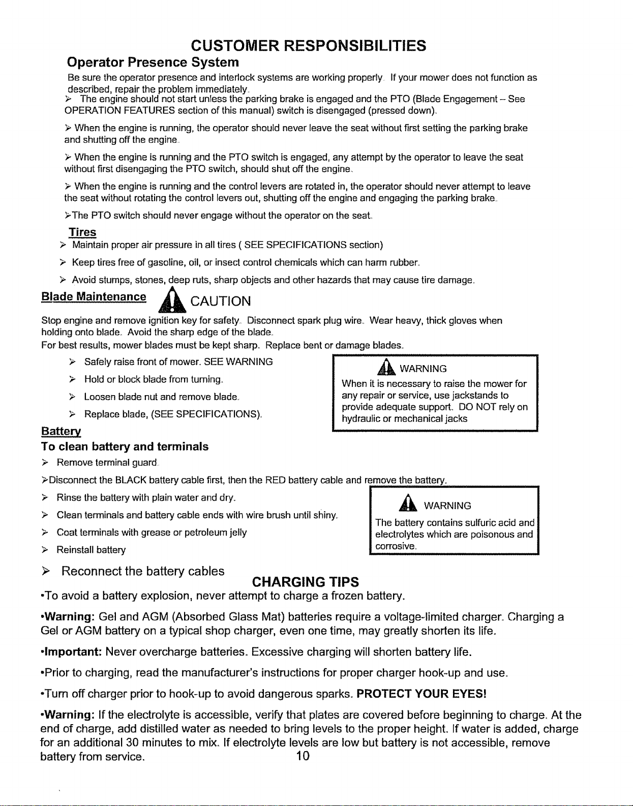
CUSTOMER RESPONSIBILITIES
Operator Presence System
Be sure the operator presence and interlock systems are working properly If your mower does not function as
described, repair the problem immediately.
;_ The engine should not start unless the parking brake is engaged and the PTO (Blade Engagement- See
OPERATION FEATURES section of this manual) switch is disengaged (pressed down)_
> When the engine is running, the operator should never leave the seat without first setting the parking brake
and shutting off the engine..
When the engine is running and the PTO switch is engaged, any attempt by the operator to leave the seat
without first disengaging the PTO switch, should shut off the engine.
When the engine is running and the control levers are rotated in, the operator should never attempt to leave
the seat without rotating the control levers out, shutting off the engine and engaging the parking brake..
>The PTO switch should never engage without the operator on the seat..
Tire.___ss
Maintain proper air pressure in all tires ( SEE SPECIFICATIONS section)
> Keep tires free of gasoline, oil, or insect control chemicals which can harm rubber_
Avoid stumps, stones, deep ruts, sharp objects and other hazards that may cause tire damage..
Blade Maintenance ,_ CAUTION
Stop engine and remove ignition key for safety.. Disconnect spark plug wire. Wear heavy, thick gloves when
holding onto blade° Avoid the sharp edge of the blade..
For best results, mower blades must be kept sharp.. Replace bent or damage blades.
Battery
Safely raise front of mower,,SEE WARNING
Hold or block blade from turning.
Loosen blade nut and remove blade,
Replace blade, (SEE SPECIFICATIONS),,
To clean battery and terminals
Remove terminal guard.
,_ WARNING
When it is necessary to raise the mower for
any repair or service, use jackstands to
provide adequate support.. DO NOT rely on
hydraulic or mechanical jacks
Disconnect the BLACK battery cable first, then the RED battery cable and remove the battery.
I
_. Rinse the battery with ptain water and dry,. ,_ WARNING I
Clean terminals and battery cable ends with wire brush until shiny, The battery contains sulfudc acid and |
> Coat terminals with grease or petroleum jelly electrolytes which are poisonous and
,_ Reinstall battery corrosive: I
Reconnect the battery cables
CHARGING TIPS
•To avoid a battery explosion, never attempt to charge a frozen battery.
•Warning: Gel and AGM (Absorbed Glass Mat) batteries require a voltage-limited charger. Charging a
Gel or AGM battery on a typical shop charger, even one time, may greatly shorten its life.
•Important: Never overcharge battedes_ Excessive charging will shorten battery life.
-Prior to charging, read the manufacturer's instructions for proper charger hook-up and user
•Turn off charger prior to hook-up to avoid dangerous sparks,. PROTECT YOUR EYES!
-Warning: If the electrolyte is accessible, verify that plates are covered before beginning to charge. At the
end of charge, add distilled water as needed to bring levels to the proper height. If water is added, charge
for an additional 30 minutes to mix,. If electrolyte levels are low but battery is not accessible, remove
battery from service. I 0
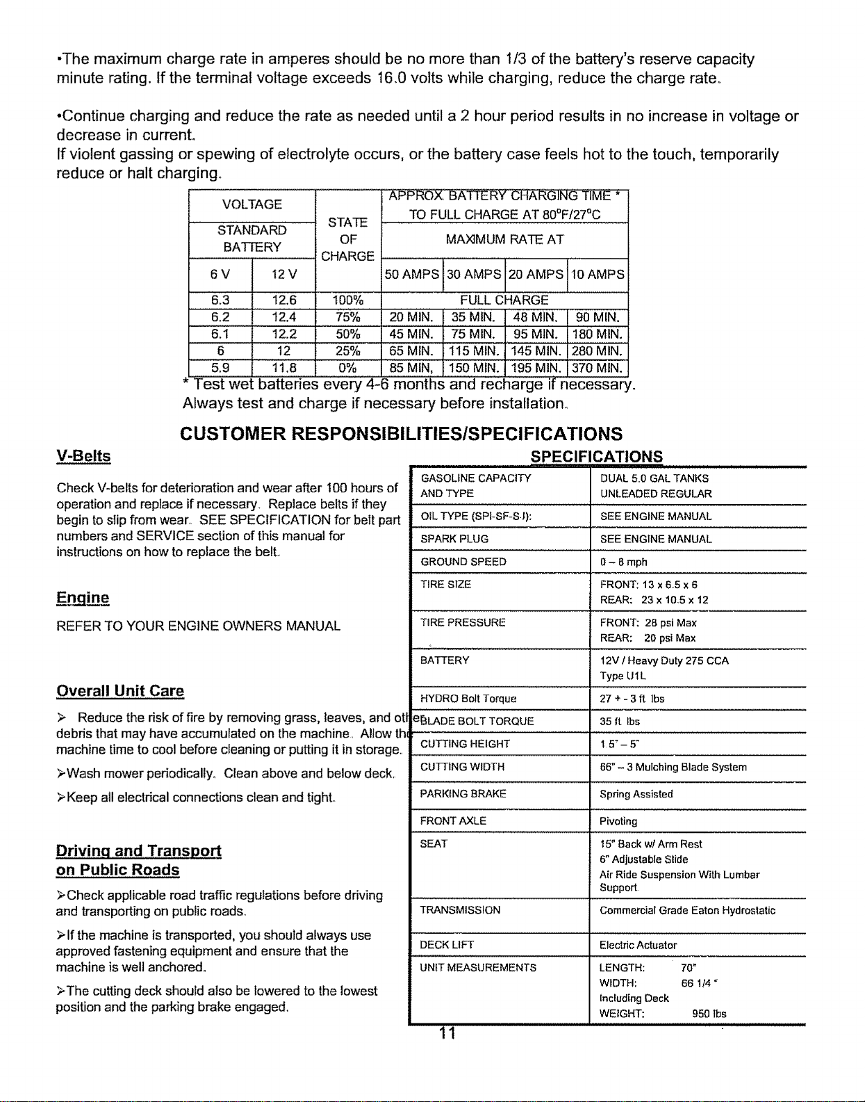
-Themaximumchargeratein amperesshouldbe nomorethan I/3 ofthe battery'sreservecapacity
minuterating.Ifthe terminalvoltageexceeds16.0voltswhile charging,reducethechargerate,,
•Continuechargingand reducetherateasneededuntila2 hourperiodresultsin no increasein voltageor
decreasein currenL
Ifviolentgassingorspewingofelectrolyteoccurs,orthebatterycasefeels hotto thetouch,temporarily
reduceor haltcharging_
APPROX BATTERY CHARGING TIME *
VOLTAGE
TO FULL CHARGE AT 80°Ff27°C
.................. STATE , , ,
STANDARD
OF MAX]MUM RATE AT
BATTERY
CHARGE
6V 12V
6.3 t2.6
......612................12.4
6.1 12.2
6 12
5,9 i 1.8
100%
75%
5O%
25%
O%
50 AMPS 30 AMPS 20 AMPS 10 AMPS
FULL CHARGE
20 MIN. 35 MIN. 48 MIN. 90 MIN.
45 MINI 75 MIN. 95MIN. 180 MIN.
65 MIN. 115MIN. 145 MIN. 280 MIN.
85 MtN, 150MIN. 195 MIN. 370 MIN.
* Test wet batteries every 4-6 months iar'ge:if necessary.
Always test and charge if necessary before installation°
V-Belts
CUSTOMER RESPONSIBILITIES/SPECIFICATIONS
,SPECIFICATIONS ..................
Check V-belts for deterioration and wear after 100 hours of
operation and replace if necessary_ Replace belts if they
begin to slip from wear,, SEE SPECIFICATION for belt part
numbers and SERVICE section of this manual for
instructions on how to replace the belt,,
Engine
REFER TO YOUR ENGINE OWNERS MANUAL
Overall Unit Care
> Reduce the dsk of fire by removing grass, leaves, and otl
debris that may have accumulated on the machine. Allow the
machine time to cool before cleaning or putting it in storage.
>Wash mower periodically° Clean above and below deck..
>Keep all electrical connections clean and tight..
Drivinq and Transport
on Public Roads
>Check applicable road traffic regulations before driving
and transporting on public roads,
>if the machine is transported, you should always use
approved fastening equipment and ensure that the
machine is well anchored°
>The cutting deck should also be lowered to the lowest
positionand the parking brake engaged,,
GASOLINE CAPACITY
AND TYPE
OIL TYPE (SPI-SF-S.J):
SPARK PLUG
GROUND SPEED
TIRE SIZE
TIRE PRESSURE
BATTERY
HYDRO Bolt Torque
B_LADE BOLT TORQUE
CUTTING HEIGHT
CU_ING WIDTH
PARKING BRAKE
FRONT AXLE
SEAT
TRANSMISSION
DECK LIFT Electric Actuator
UNIT MEASUREMENTS
11
DUAL 5..0 GAL TANKS
UNLEADED REGULAR
SEE ENGINE MANUAL
SEE ENGINE MANUAL
0- 8 mph
FRONT: 13 x6.5 x 6
REAR: 23x10.5x12
FRONT; 28 psi Max
REAR: 20 psi Max
12V ! Heavy Duty 275 CCA
Type U1L
27+-3ftlbs
35 ft lbs
15"-5"
66" - 3 Mulching Blade System
Spring Assisted
Pivoting
15" Back wl Arrn Rest
6" Adjustable Slide
Air Ride Suspension With Lumbar
Support
Commercial Grade Eaton Hydrostatic
LENGTH: 70"
WIDTH: 66 1/4 _
IncludingDeck
WEIGHT: 950Ibs
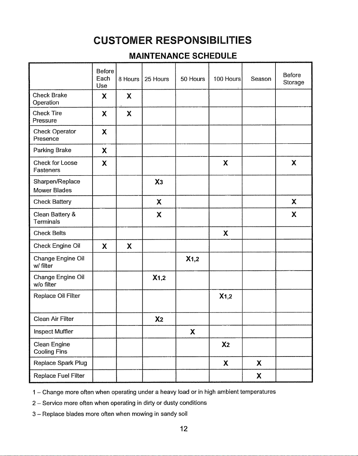
CUSTOMER RESPONSiBiLITIES
Check Brake
Operation
Check Tire
Pressure
Check Operator
Presence
Parking Brake
Check for Loose
Fasteners
SharpenlReplace
Mower Blades
Check Battery
Clean Battery &
Terminals
Check Belts
Check Engine Oil
Change Engine Oil
w! filter
Change Engine Oil
wlo filter
Replace Oil Filter
Clean Air Filter
inspect Muffler
Clean Engine
Cooling Fins
Replace Spark Plug
Replace Fuel Filter
MAINTENANCE SCHEDULE
Before
Each 8 Hours
Use
X X
X X
X
X
X
X X
25 Hours
X3
X
X
50 Hours
X2
Xl,2
100 Hours
X
......... 1....................
X
X1,2
X1,2
X
X2
Before
Season
Storage
X X
X
X
X
X
1 - Change more often when operating under a heavy load or in high ambient temperatures
2 - Service more often when operating in dirty or dusty conditions
3 - Replace blades more often when mowing in sandy soil
12
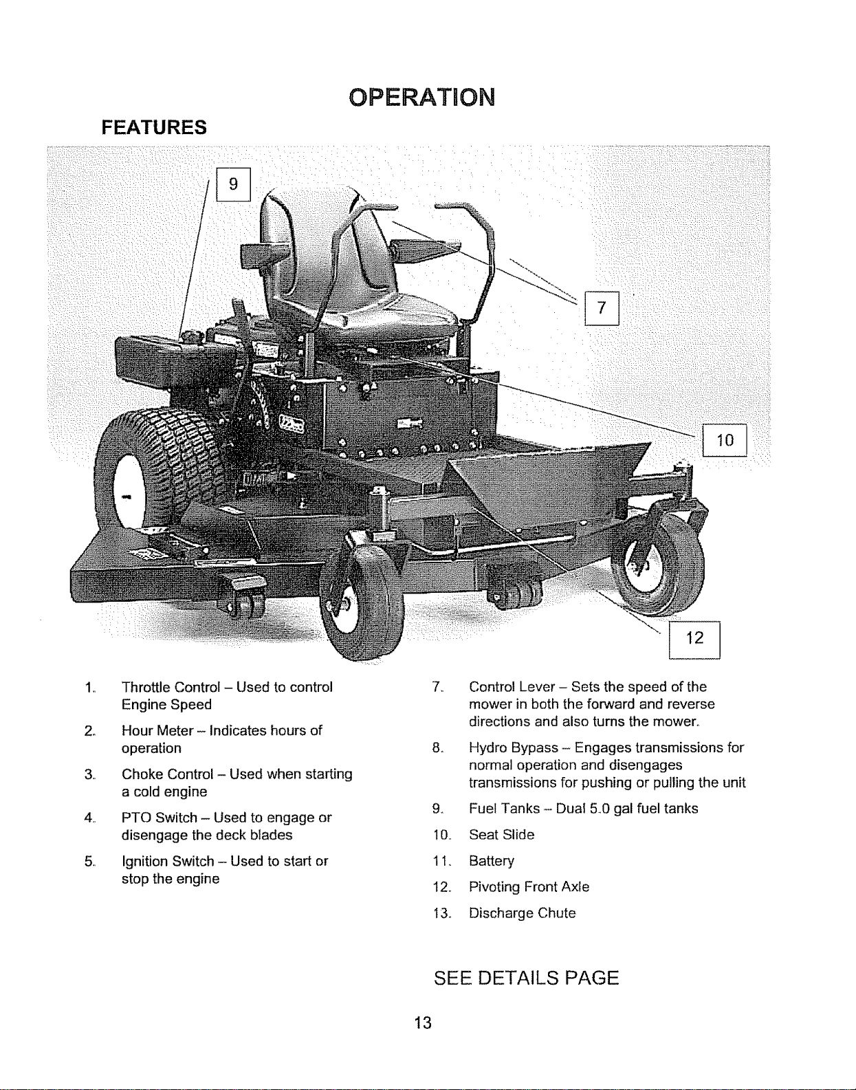
FEATURES
/
/
OPERATION
,,
2_
,,
,,
,,
Throttle Control- Used to control
Engine Speed
Hour Meter- Indicates hours of
operation
Choke Control- Used when starting
a cold engine
PTO Switch - Used to engage or
disengage the deck blades
Ignition Switch - Used to start or
stop the engine
: :::: : : :: :i::i: ¸ :
,,
.
9_
I0.,
1 1,,
12,,
13.,
Control Lever - Sets the speed of the
mower in both the forward and reverse
directions and also turns the mower,
Hydro Bypass - Engages transmissions for
normal operation and disengages
transmissions for pushing or pulling the unit
Fuel Tanks - Dual 5_0 gal fuel tanks
Seat Slide
Battery
Pivoting Front Axle
Discharge Chute
SEE DETAILS PAGE
13
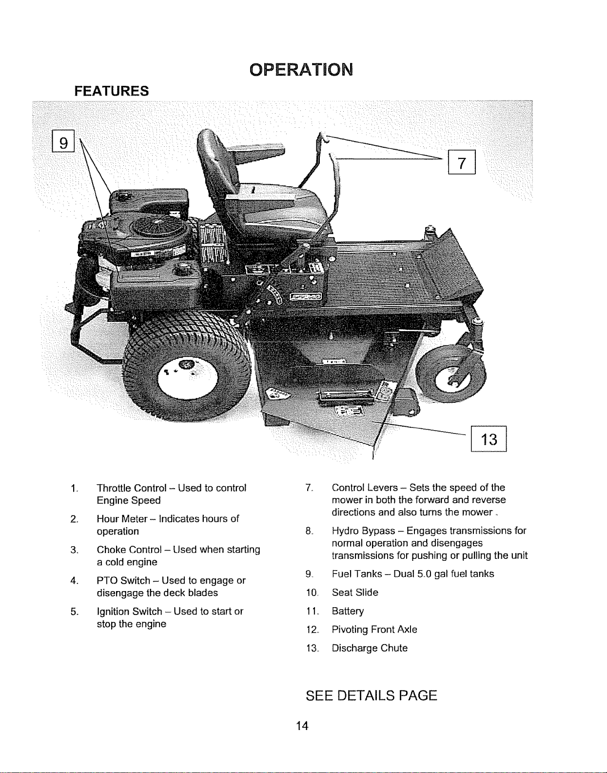
FEATURES
OPERATRON
,•
2_
34
4.
.
Throttle Control - Used to control
Engine Speed
Hour Meter- Indicates hours of
operation
Choke Control - Used when starting
a cold engine
PTO Switch- Used to engage or
disengage the deck blades
Ignition Switch - Used to start or
stop the engine
,,
.,
Control Levers - Sets the speed of the
mower in both the forward and reverse
directions and also turns the mower.
Hydro Bypass - Engages transmissions for
normal operation and disengages
transmissions for pushing or pulling the unit
g_
10, Seat Slide
11,, Battery
12, Pivoting Front Axle
I3., Discharge Chute
Fuel Tanks - Dual 5.0 gat fue! tanks
SEE DETAILS PAGE
14
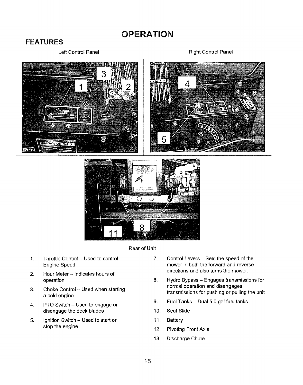
OPERATION
Left Control Panel
Right Control Panel
2_
34
4_
54
Throttle Control - Used to control
Engine Speed
Hour Meter- Indicates hours of
operation
Choke Control - Used when starting
a cold engine
PTO Switch - Used to engage or
disengage the deck blades
Ignition Switch - Used to start or
stop the engine
Rear of Unit
7_
84
g,_
10_
tl.
12,
13,,
Control Levers - Sets the speed of the
mower in both the forward and reverse
directions and also turns the mower°
Hydro Bypass - Engages transmissions for
normal operation and disengages
transmissions for pushing or pulling the unit
Fuel Tanks - Dual 5°0 gal fuel tanks
Seat Slide
Battery
Pivoting Front Axle
Discharge Chute
15
OPERATION
Starting
Operator must be sitting in the seat,. Control handles must be in the neutral
(outward) position, PTO must be in the disengage position (pushed down)_
> Set choke (if needed), turn key and release as soon as engine starts. Adjust
throttle to half and shut choke off.
> Be sure all people are clear of the area. Set engine RPM to maximum and then
engage blades.
Grass Height & Cutting Suggestions
Do not attempt to cut wet grass
NOTE:
If you have never used a Zero
Turn mower before, refer to the
Operation Controls section of
this manual before attempting
to operate one for the first time.
The average lawn should be cut to 2 ½" during the cool season and to over 3"
during the hot months, For healthier and better looking lawns, mow often and after
moderate growth.
As a rule, never cut more than 1/3 of the total grass blade length. Correct
mowing height can reduce weeds and lawn disease.
> For best performance, grass over 6 inches in height should be mowed twice°
The first cut should be set relatively high and the second set to the desired height,,
16
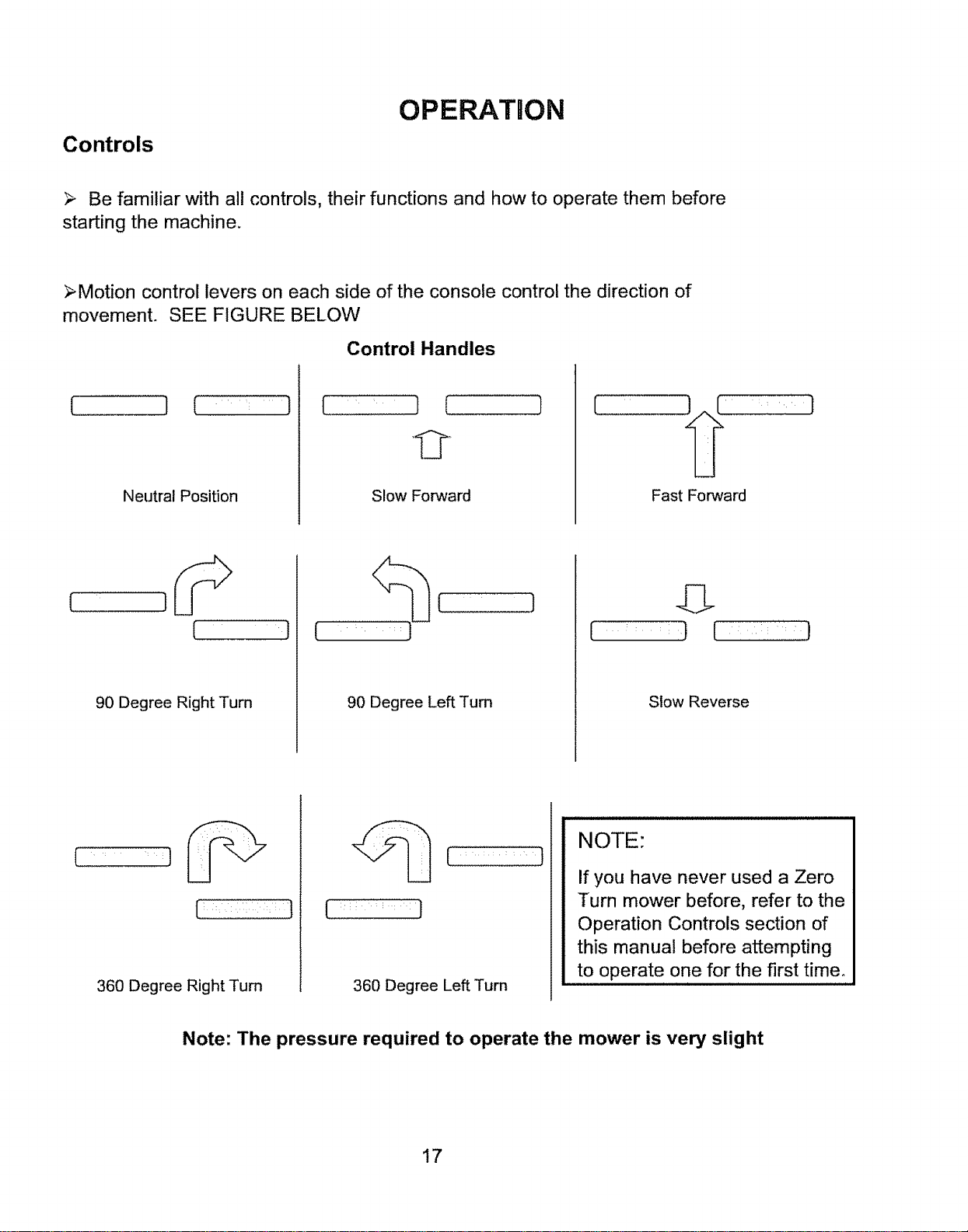
Controls
OPERATION
Be familiar with all controls, their functions and how to operate them before
starting the machine.
>Motion control levers on each side of the console control the direction of
movement. SEE FIGURE BELOW
Control Handles
Neutral Position Slow Forward Fast Forward
90 Degree Right Turn 90 Degree Left Turn
Slow Reverse
H • •• • 1
360 Degree Right Turn 360 Degree Left Turn
NOTE:
If you have never used a Zero
Turn mower before, refer to the
Operation Controls section of
this manual before attempting
to operate one for the first time°
Note: The pressure required to operate the mower is very slight
17
SERVICE & ADJUSTMENTS
Adjustinq The Cutting Hei.,qht
> Use the actuator switch to raise or lower the deck to thedesired position..
>- Position 1 isthe lowest setting and Position 8 is the highest position
> The cutting range is from approximately 1 ½" to approximately 5"
Deck Levelinq
TOOLS REQUIRED:
_ 2 - W' Wrenches or ½" Socket with drive ratchet
> Lower the cutting deck down to the lowest position (position 1)
> Loosen the nuts on the top side of the deck hanger brackets (3 places) where the lift chains attach tom
>. With all three loose on top of the brackets the deck should now set on the ground resting on the roller
wheels,,
> Tighten the nuts on the top of the lift brackets making sure that all three lift chains are pulled tight.,
> Lift deck using the deck lift handle to the desired position
Parkinq Brakes
,/The Swisher ZT2766KZ is equipped with An Automatic Parking Brake system on each control handle_.
,/When the control handles are in the out most position the parking brakes are one.
,/Adjustment for the system is located on the ends of the brake cable at the hydro pan & frame..
,/Raise the rear wheel off the ground
`/Disengage the hydro to be adjusted with the hydro release handle at the rear of the unit
`/Adjust so that the brake is not on when the handles are in the operator position,, The wheel should turn freely.
,/The wheel should not turn when the handle is moved to the engaged or outward position..
,/To tighten the brake, tum the adjustment nuts towards the end of the cable
,/Recheck adjustment with control handle
,/Lower unit back to the ground
,/Reengage the hydro at the rear of the unit
WARNING
When it is necessary to raise the mower for any
repair or service, use jackstands to provide
adequate support, DO NOT rely on hydraulic or
mechanical jacks
18
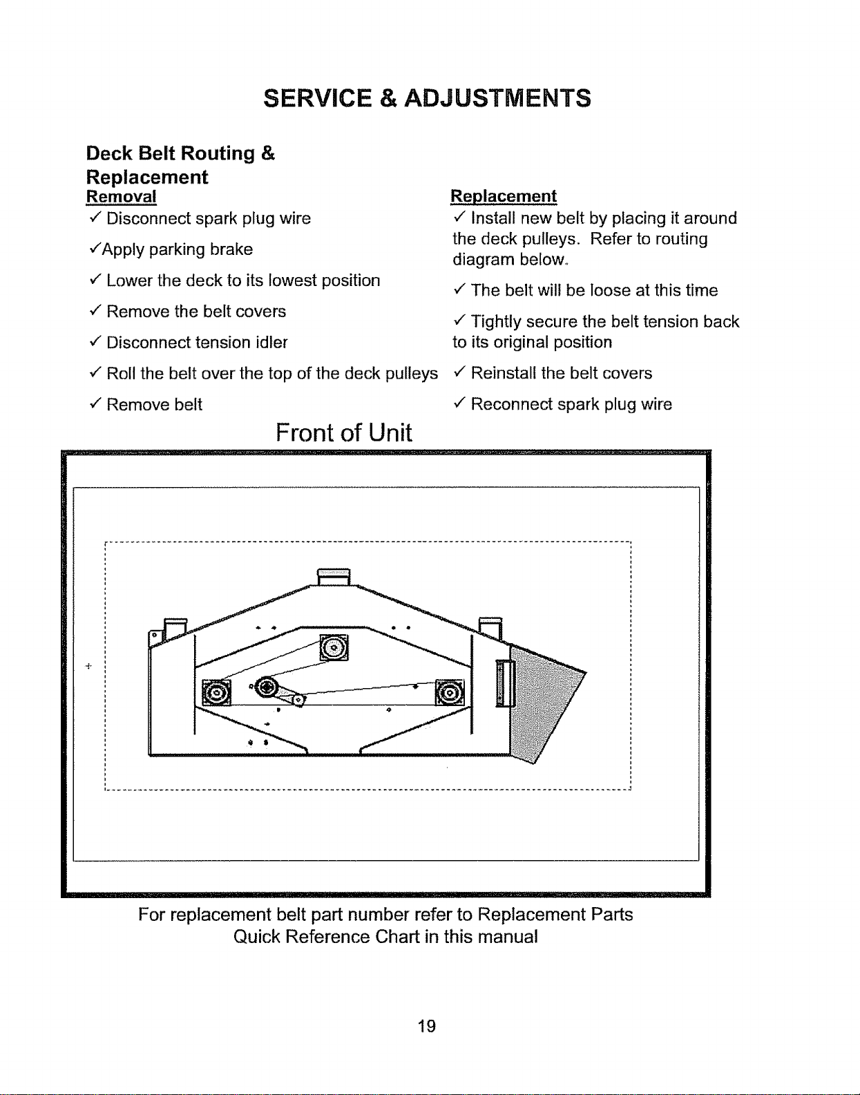
SERVICE & ADJUSTMENTS
Deck Belt Routing &
Replacement
Removal
¢" Disconnect spark plug wire
-/'Apply parking brake
/ Lower the deck to its lowest position
v" Remove the belt covers
/ Disconnect tension idler
Roll the belt over the top of the deck pulleys
¢" Remove belt
Front of Unit
v" Install new belt by placing it around
the deck pulleys. Refer to routing
diagram below.
v"The belt will be loose at this time
v" Tightly secure the belt tension back
to its original position
v"Reinstall the belt covers
¢" Reconnect spark plug wire
÷
For replacement belt part number refer to Replacement Parts
Quick Reference Chart in this manual
19
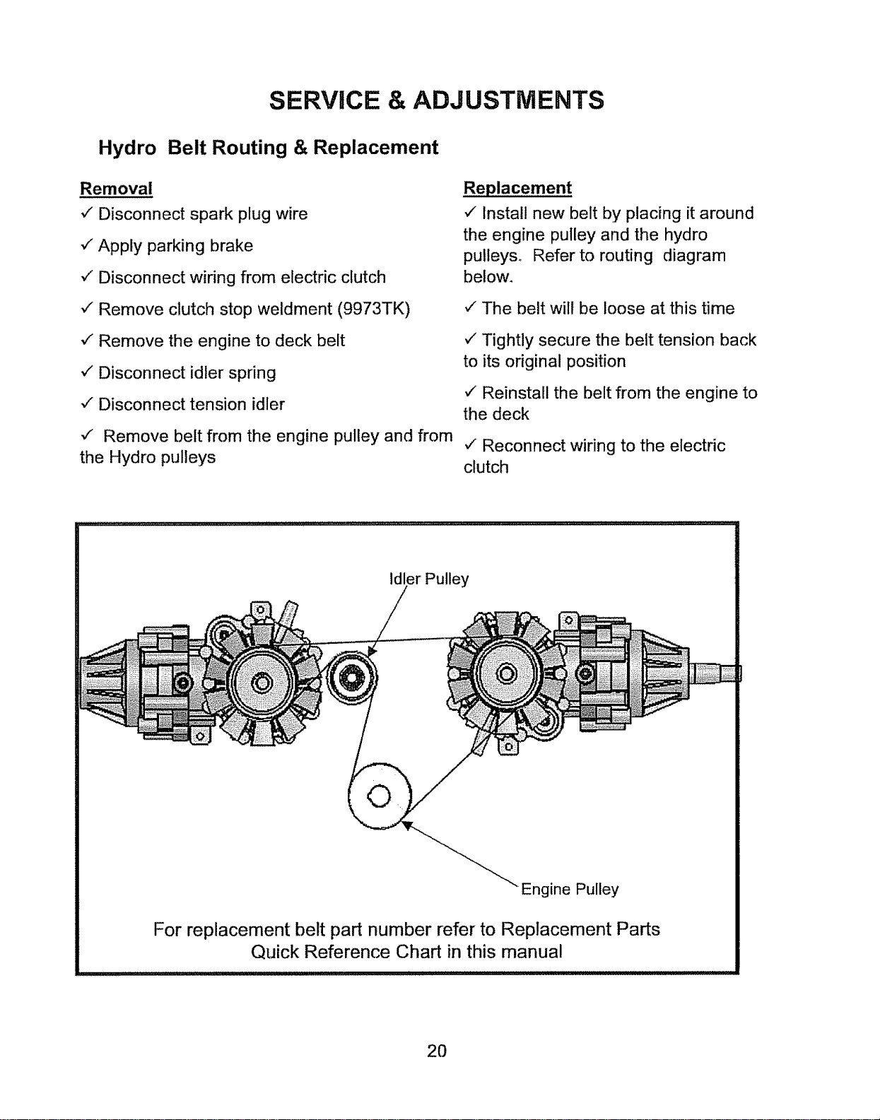
SERVICE & ADJUSTMENTS
Hydro Belt Routing & Replacement
Removal
•/ Disconnect spark plug wire
,/Apply parking brake
•/ Disconnect wiring from electric clutch
-/Remove clutch stop weldment (9973TK)
•/ Remove the engine to deck belt
•/ Disconnect idler spring
-/Disconnect tension idler
v" Remove belt from the engine pulley and from
the Hydro pulleys
Replacement
•/ Install new belt by placing it around
the engine pulley and the hydro
pulleys° Refer to routing diagram
below.
,/" The belt wilt be loose at this time
v" Tightly secure the belt tension back
to its original position
,/Reinstall the belt from the engine to
the deck
,/Reconnect wiring to the electric
clutch
Idler Pulley
Engine Pulley
For replacement belt part number refer to Replacement Parts
Quick Reference Chart in this manual
20
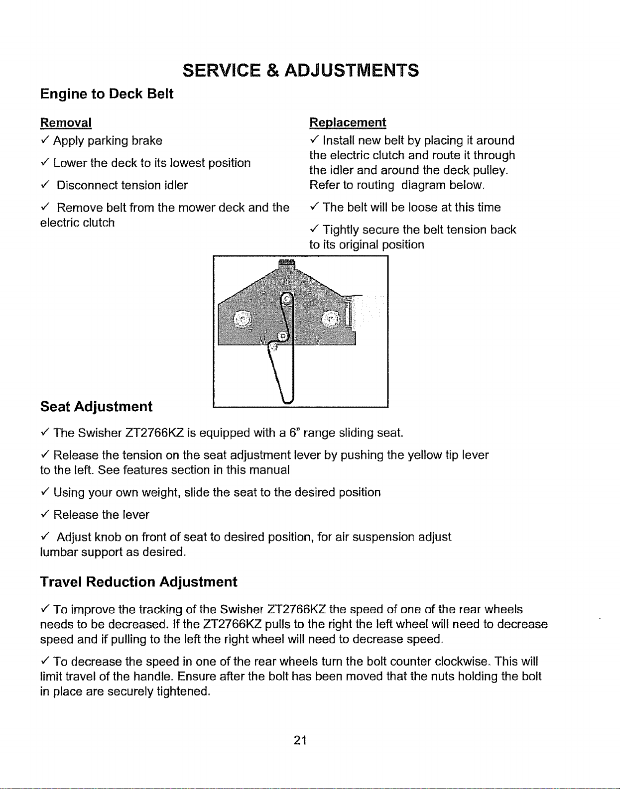
Engine to Deck Belt
SERVICE & ADJUSTMENTS
Removal
v" Apply parking brake
v" Lower the deck to its lowest position
,/ Disconnect tension idler
v" Remove belt from the mower deck and the
electric clutch
Replacement
v" install new belt by placing it around
the electric clutch and route it through
the idler and around the deck pulley..
Refer to routing diagram below.
v" The belt will be loose at this time
,/Tightly secure the belt tension back
to its original position
Seat Adjustment
,," The Swisher ZT2766KZ is equipped with a 6" range sliding seat.
v" Release the tension on the seat adjustment lever by pushing the yellow tip lever
to the left. See features section in this manual
v" Using your own weight, slide the seat to the desired position
,," Release the lever
v" Adjust knob on front of seat to desired position, for air suspension adjust
lumbar support as desired.
Travel Reduction Adjustment
v" To improve the tracking of the Swisher ZT2766KZ the speed of one of the rear wheels
needs to be decreased. If the ZT2766KZ pulls to the right the left wheel will need to decrease
speed and if pulling to the left the right wheel will need to decrease speed.
v" To decrease the speed in one of the rear wheels turn the bolt counter clockwise. This will
limit travel of the handle. Ensure after the bolt has been moved that the nuts holding the bolt
in place are securely tightened..
21
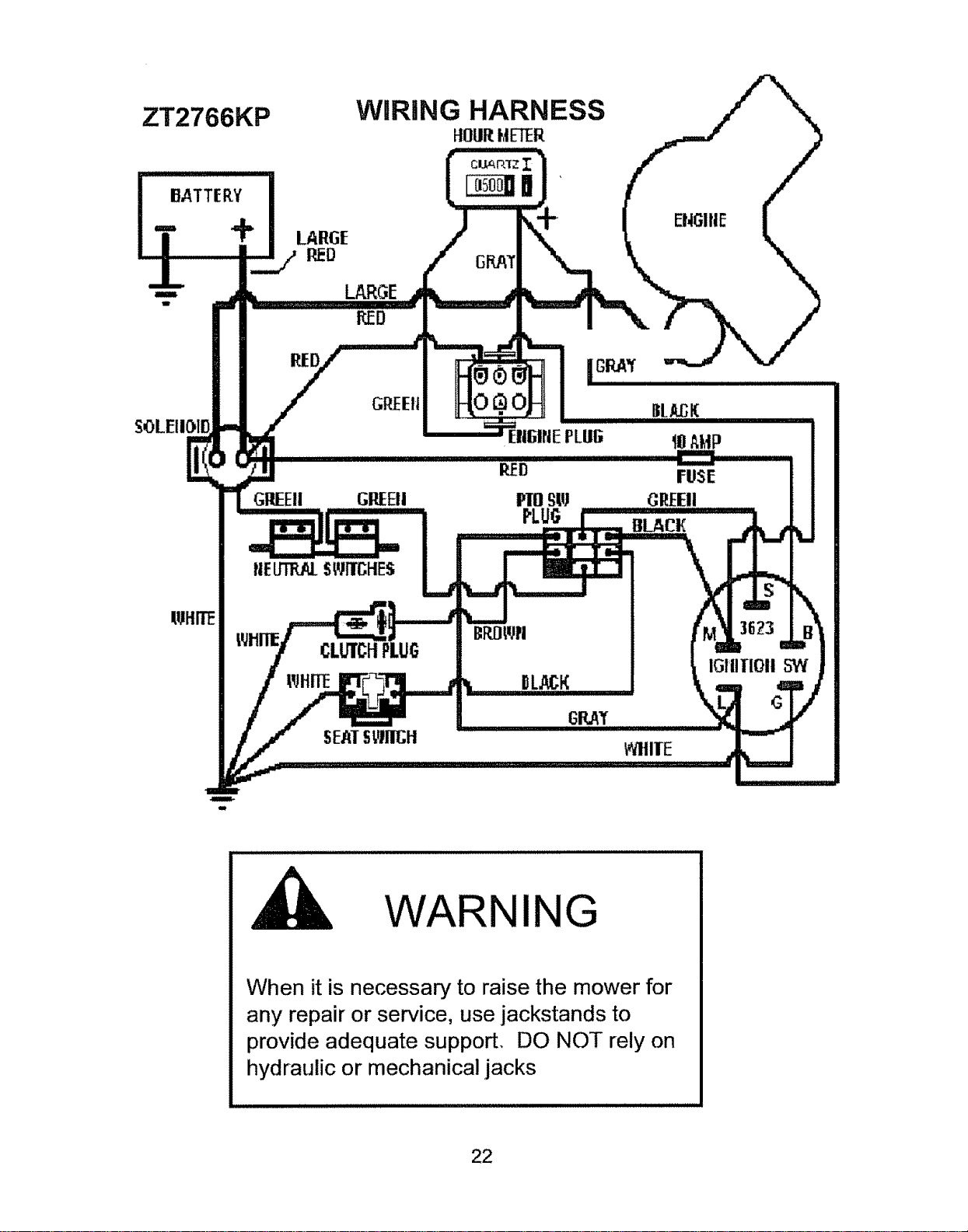
ZT2766KP
WiRiNG HARNESS
FLOURHE_ER
i
i
LARGE
RED
LARGE
RED
RED
GREEII
GREEII GP.EEII
CLUTCHPLUG
IpJHITE
ENGIIIE
BLA_K
10AMP
FUSE
GREEII
BLACK
IGIIITIOIi 5W
WARNING
When it is necessary to raise the mower for
any repair or service, use jackstands to
provide adequate support. DO NOT rely on
hydraulic or mechanical jacks
22
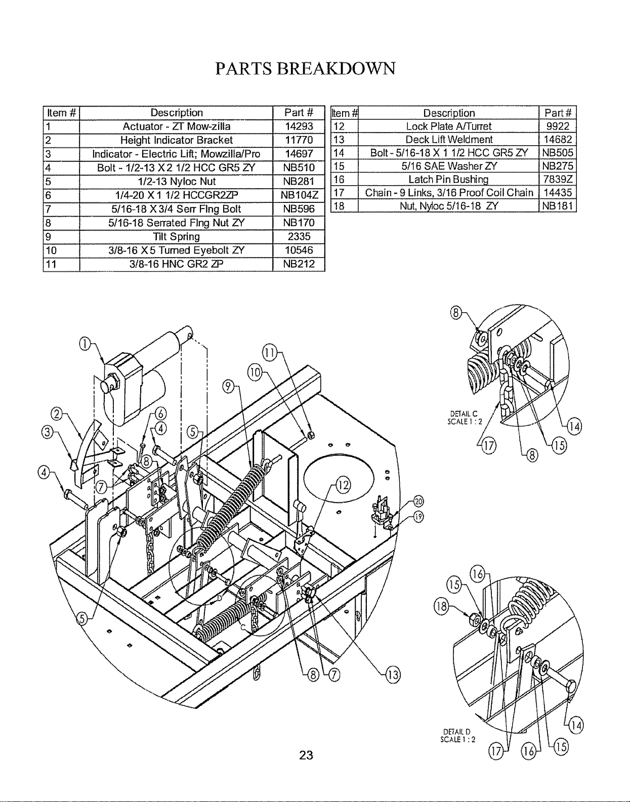
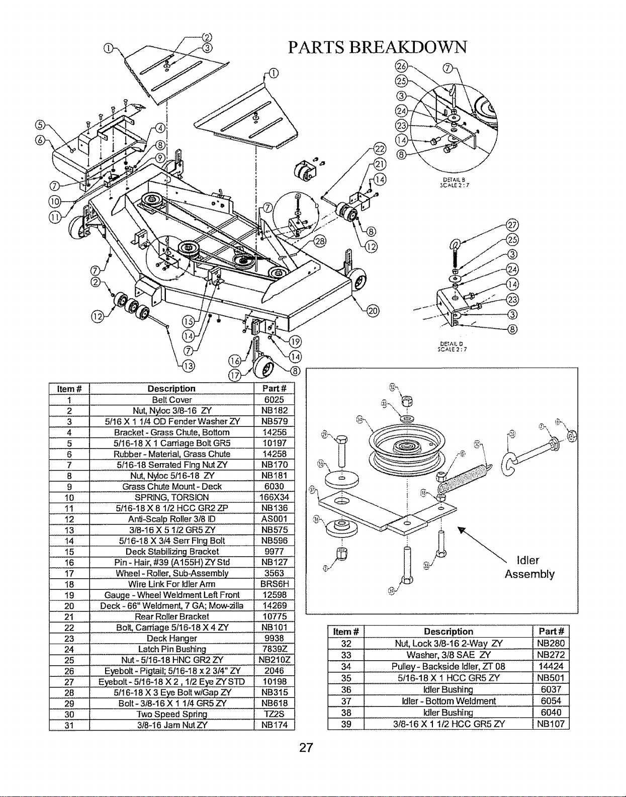
PAd ..TS BREAKDOWN
Item # Description Part #
1 Actuator - ZT Mow-zilla 14293
2 Height Indicator Bracket 11770
: :
3 Indicator- Electric Lift; Mowzilfa/Pro 14697
4 Bolt - I/2-13 X2 1/2 HCC GR5 ZY NB510
5 1/2-13 Nyloc Nut NB281
6 1/4-20 X 1 112 HCCGR__27_ NBI04Z
7 5116-18 X 314 Serf Flng Bolt NB596
8 5116218 Serrated Flng Nut ZY NB170
9 Tilt Spring 2335
10 3/8-16 X 5 Turned Eyebolt ZY 10546
1i 318-1'6 HNC GR2 ZP NB21'2"
Item# DescdPti0n
12 Lock Plate A/Turret
1 ................................ q
13 Deck Lift Weldment
14 Bolt- 5/16-18 X t 1/2 HCC GR5 ZY
15
16
17
!8
Part#
9922
14682
NB505
5/16 SAE Washer ZY NB275
Latch Pin Bushing 7839Z
Chain - 9 Links, 3/16 Proof Coil Chain, 144,35.
NUt,NYt0C5/!6,!8 ZY NB181
23
Dk'TAILD
SCALE 1 : 2
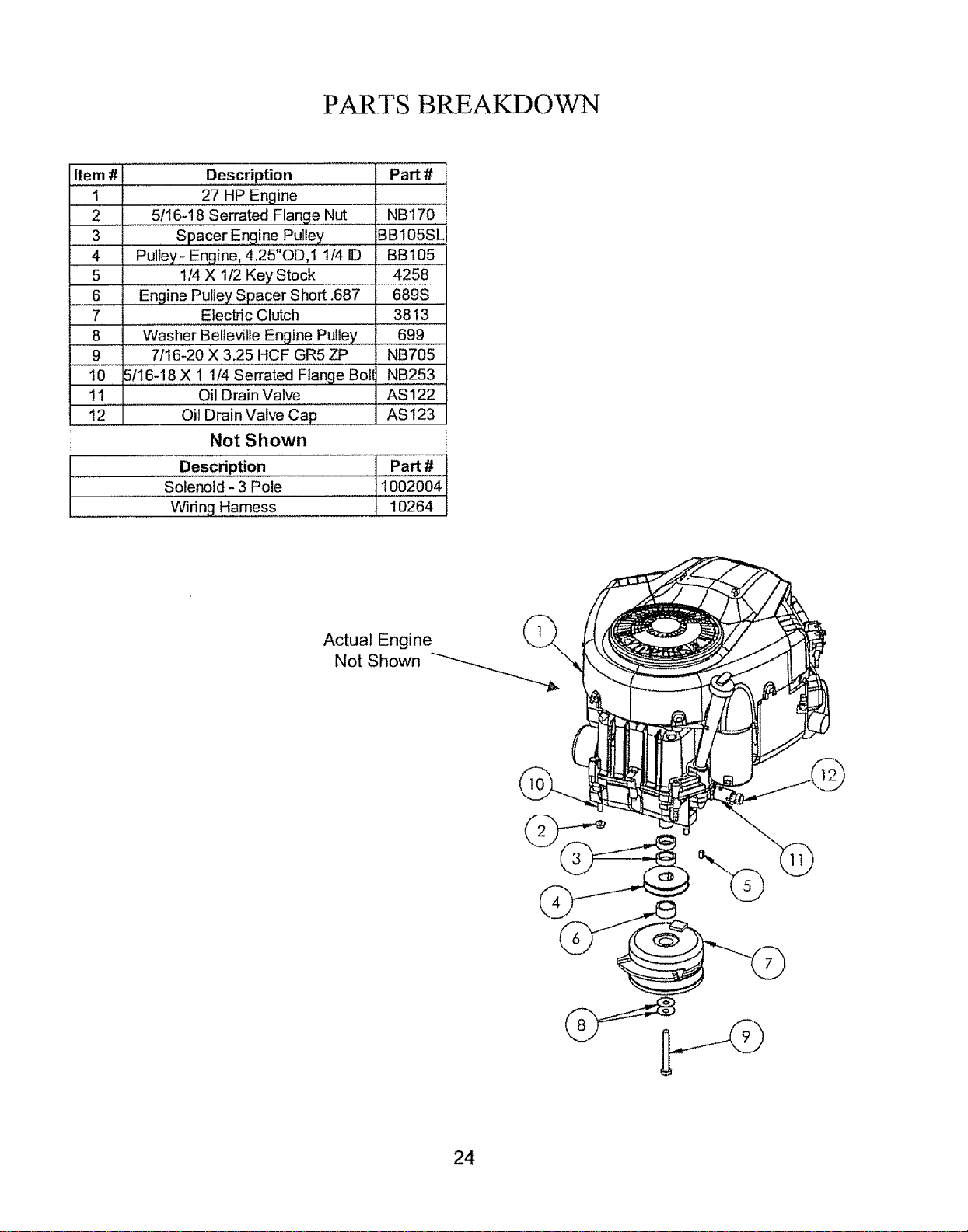
PARTS BREAKDOWN
Item #
1
2
3
4
5
.........
7
8
9
!0 5/16-18 X 1 t/4 Serrated Flange Bol!
11 Oil Drain Valve
12 Oil Drain Valve Cap
Not Shown
Description Part #
27 HP Engine
"5/16-18 Serrated Flange Nut NBi70 ....
Spacer Eng.!ne Pulley BB 105SL
Pulley _Engine, 4.25"OD,1 1/4 ID ....BB105 =
1/4 X 1/2 Key .Stock ..... 4258
Engine Pulley Spacer Short .687 689S
Electric Clutch 3813
....Washer Belleville Engine Pu[!eY 1699
7/16-20 X 3.25 HCF GR5 ZP NB705
NB253
AS 122
AS 123
.....Description
Solenoid - 3 Pole
Widng Hamess
PaN#
:1002004
10264
Actual Engine (_
Not Shown
24
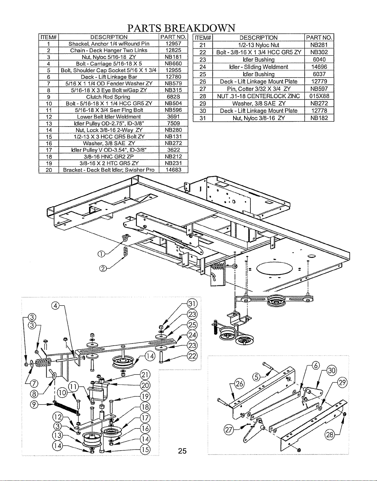
PARTS BREAKDOWN
ITEM# DESCRIPTION PART NO.
! ..... Shackel, Anchor 114w/Round Pin 12957
2 Chain- Deck HangerTwo Links :_ 12825 .....
3 Nut, Nytoc 5t16-18 ZY NB181
4 Bolt- Carriage 5t16-18 X 5 NB660
5 Bolt, Shoulde[ Cap Socket 5116 X 1314 12955 .....
6 .... Deck - Lift L!nkage Bar 1278.0.
7 5116 X I 114OD Fender Washer ZY NB579
8 5/16-18 X 3 Eye Bolt wlGap ZY NB315
9 Clutch Rod Spdng 682S
10 ........Bo!t- 5116-I8 X 1 114HCC GR5 ZY NB504
11 5/16-I8 X 3/4 Sen" Flng Bolt NB596
12 Lower Belt Idler Weldment 3691
13 Idle[ Pulley OD-2.75", ID-3f8" .=_7508 ........
14 Nut, Lock 3/8-16 2-Way. ZY NB280
15 1/2-13 X 3 HCC GR5 Bolt ZY NBI31
16 Washe.r, 318 SAE ZY NB272
17 Idler Pulley V OD-3.54" ID-318" 3622
18 3t8-16 HNC GR2 ZP NB212
19 3/8-16 X 2 HTC GR5 ZY NB231
20 Bracket - Deck' Beii'idier, Swisher Pro 14683
ITEM# DESCRIPTiON PART NO.
21 112-13 Nyioc Nut NB281 .....
22 Bolt- 3/8-16 X 1 3/4 HCC GR5 ZY NB302
23 Id!e.[..Bushing 6040
., 24 Idler- Sliding Weldment 14696
25 ......Id.!e[..Bushing 6037
.....26 Deck - Lift Linkage Mount Plate 12779
27 .......Pin, Cotter 3f32 X 314 ZY NB597
28 NUT .31-18 CENTERLOCK ZINC 015X88
......29 ...................................Washer, 318SAE ZY NB272
=
30 Deck - Lift Linkage Mount Plate 12778
31 Nut, Nybc 3t8-16 ZY NB182
25
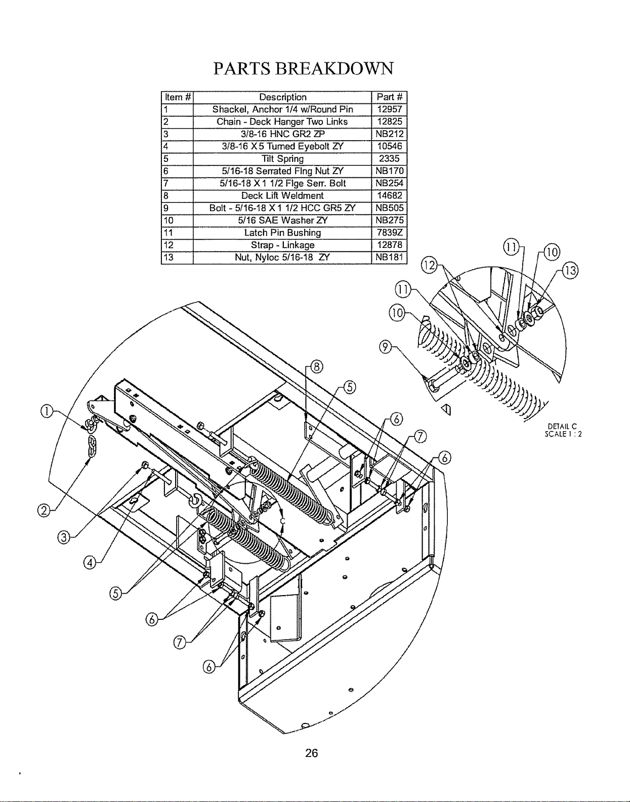
PARTS BREAKDOWN
Item # Description Part #
t Shackel, Anchor 1/4 wlRound Pin 12957
2 Chain ' Deck Hanger Two Links 12825
3 3t8-16 HNC GR2 ZP NB212
4 3/8-16 X 5 Turned Eyebolt ZY 10546
5 ' ]lit Spring ..... 2335
6 5ii6'18 seated Flng Nut ZY NBi7'0
7 5/16-i8 X 1 112 Flge Serr. Bolt NB254
8 Deck Li_ Weldment 14682
9 Bolt - 5116-18 X 1 112 HCC GR5 ZY NBh05
i0 .................... 5f16 SAE Washer ZY NB2"75
11 . Latch Pin Bushing 7839Z
']"2 Strap - Linkage 'i 287'8'
13 Nut, Nyloc 51!6-18 ZY NB181
DEIAIL C
SCALE I : 2
26
I
i
PARTS BREAKDOWN
DETAIL _,
_,C,_LE 2 : 7
®
Item # Descr!p,tion Part #
t Belt Cover 6025
......2 Nu_Nyloc318-16 ZY NB182
3 5t16 X 1 114OD Fender Washer ZY NB579
4 Bracket - Grass Chute, Bottom I4256
5 ......5i'1"6-18X 1 Carriage Bolt GR5 30197.........
6 Rubber"_Material, Grass Chute 14258
7' ..................5fi6-i 8 seated Flng Nut ZY ' NBI"70 ....
8 .......... . oo5116-18
9 Grass Chute Mount- Deck 6030
!,0............. SPRING, TORS,ION.........................166X34
.....1!:: 51t6-18 X 8 1t2 HCC GR2 ZP ..... NB136
12 Anti-Scalp Rolter3f8 !D : AS00!.
13 318-16 X 5 1t2 GR5 ZY NB575
14 5f16-18 X 3t4 Sen-Flng BoR NB596
15 . . E)eckS_b!!!_ng Bracket 9977 ...
16 Pin- H.a.!r,...#.3.9...(A155H)ZYStd NB127
17 Wheel - Roller, Sub-Assembly 3563
18 Wire Link For Idler Arm BRS6H
19 Gauge - Wheel Weldment Left Front ::!:2598....
20 ..........Degk,,,766" Weldment, 7 GA; Mow-zilla 14269
21 Rear Roller Bracket 10775
22 ..........................................Bolt, carriage 5f16-18 x 4 ZY ...........NB!0!_
23 Deck Hanger 9938
24 Latch Pin Bushing 7839Z
25 Nut- 5!I6-18 HNC GR2 ZY NB210Z
..... 26 '"'"!......................E_looit.: Pigtail; 5116-18......................x 2 314"ZY . 2046
27 Eyebolt- 5116-18 X 2,112 Eye ZYSTD 10198
28 5116-18X 3 Eye Bolt wtGap ZY NB315
29 Bolt- 3f8-16 X 1 1t4 GR5 ZY NB618
..............30 Two Speed Spdng" TZ2S
31 318-!6 Jam NutZY NB174
DETAIL D
SCARE2 ; 7
, C.s---
_.,_ _ Idler
Assembly
Item # Description Part #
.......32 Nut. 10Ck,318:i6 2'Way ZY bIB280"
33 Washer, 3t8 SAE ZY NB272
34 Pulley- Backside Idler, ZT 08 14424
35 5t16-18 X 1 HCC GR5 ZY NB501
36 Idler Bushing 6037
37 idler- Bottom Weldment 6054
38 IdlerBushing 6040
39 3/8-16 X 1 t/2 HCC GR5 ZY NB107
27
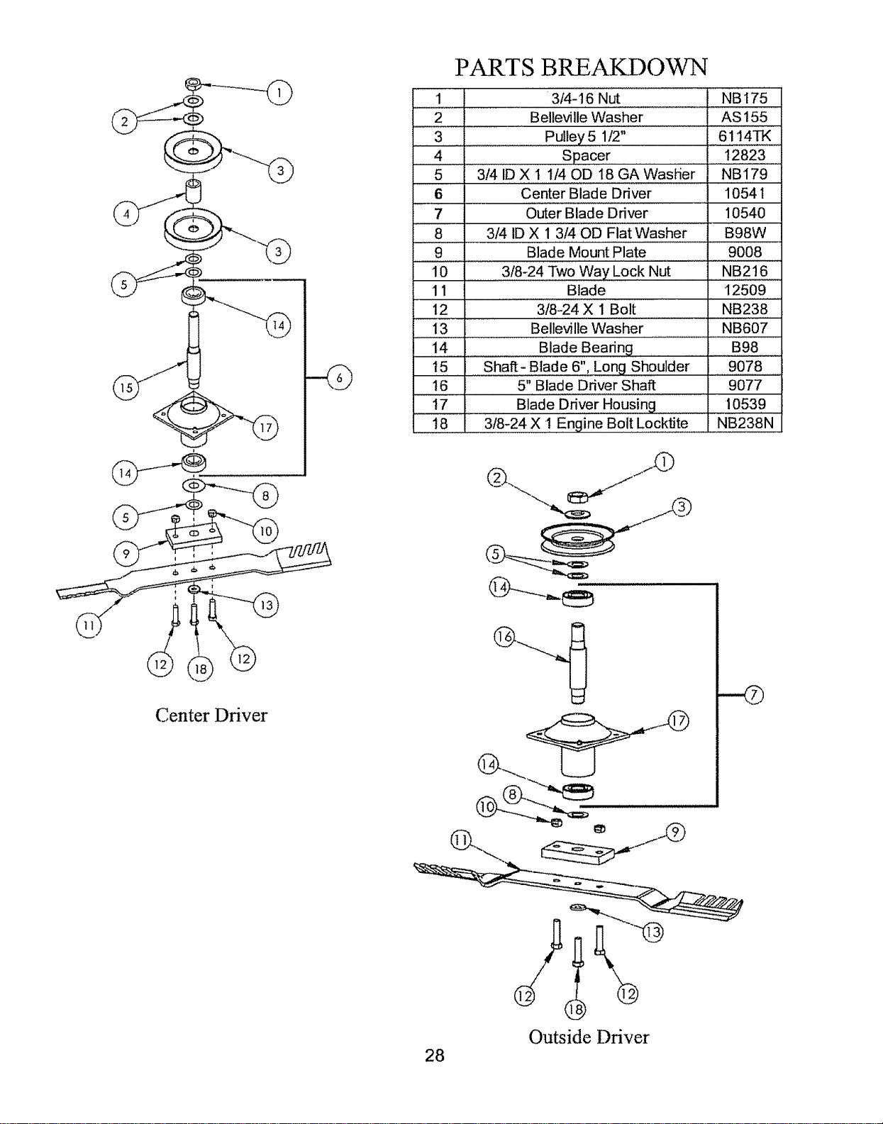
PART S BRE AKD 0 V_N
1
2
3
4
5
6
7
8
3/4-t 6 Nut NB 175
Belleville Washer AS 155
Pulley 5 1/2" 6114TK
Spacer 12823
3/4 ID X t 1/40D t8 GA WasHer NB179
Center Blade Driver 10541
Outer Blade Driver 10540
3/4 ID X 1 3/40D Flat Washer B98W
9 Blade Mount Plate 9008
10 3/8-24 Two Way Lock Nut NB216
11 Blade 12509
12 3t8-24 X 1 Bolt NB238
13 Belleville Washer NB607
14
15
16
17
18
Blade Bearing
Shaft- Blade 6", Long Shoulder
5" Blade Driver Shaft
Blade Driver Housing
3/8-24 X ! Engine Bolt Locktite
B98
9078
9077
10539
NB238N
Center Driver
28
Outside Driver
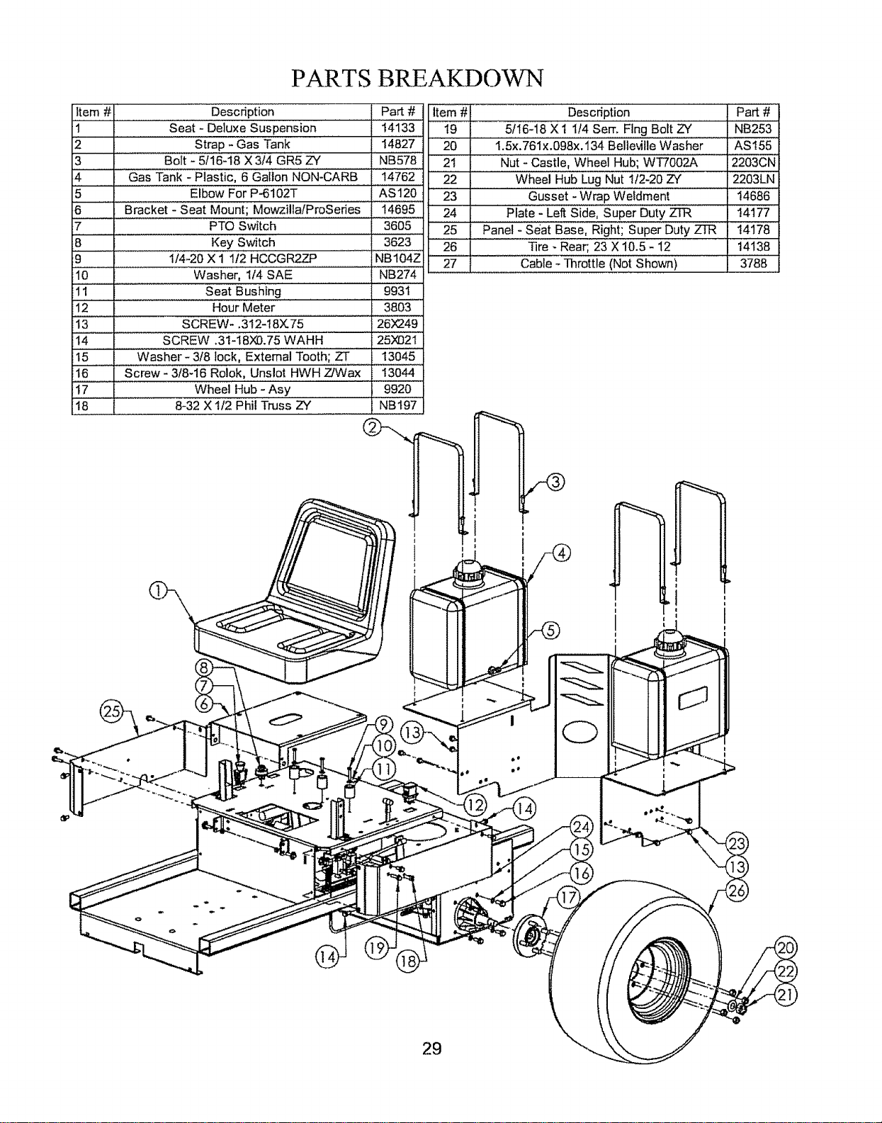
PARTS BREAKDOW-N
item # Description Part # item # . ..Des.crip!i°n................... P.a.rt#
t ..............................Seat - Deluxe Suspension 14133 19 5116+18X 1 114Serf+ Flng Bolt ZY =NB253
2 Strap - Gas Tank 14827 " 20 1.5x.761x.098x.134 Belleville Washer AS155
3 ........ Bolt 25/i 6'i8 X 3i4 GR5 zY NB'578'" 2i NUt- Castle Wheel Hub; WT7OO2A 2203CN
: .......................... :........................... s i i 1
4 Gas Tank - Plastic, 6 Gallon NON-CARB 14762
5 Elbow For P-6102T AS120
6 ...... Bracket - Seat Mount; Mowzilla/ProSeries 14695
7 PTO Switch 3605
8 Key Switch 3623
9 ............ 1/4-20 X 1 1i2 HCCGR2ZP NB104Z
10 Washer, 1/4 SAE NB274
1!............................. Seat Bushing ........ 9931 .
12 Hour Meter '3803'"
13 SCREW- .312-18X75 26_49
"1'4................... SCREW +3i+i82x13.75WAHH 25N021
15 Washer- 3f8 lock, External Tooth; ZT 13045
16 Screw - 3f8-16 Rolok, Unslot HWH Z/Wax 13044
!7.................. Wheel Hub - Asy
18 8-32 X 112 Phil Truss ZY
22 Wheel Hub Lug Nut 1f2-20 ZY 2203LN
23 ............Gusset - Wrap Weldment . 14686
24 Plate - Loll Side, Super Duty ZTR 14177
25 Panel - Seat Base, Right; Super Duty ZTR 14178
26 " Nre : Rear, 23 x 10,5 - i2 ' 14138
27 Cable +Throttle (Not Shown) 3788
9920
NB197
1
i
|
29
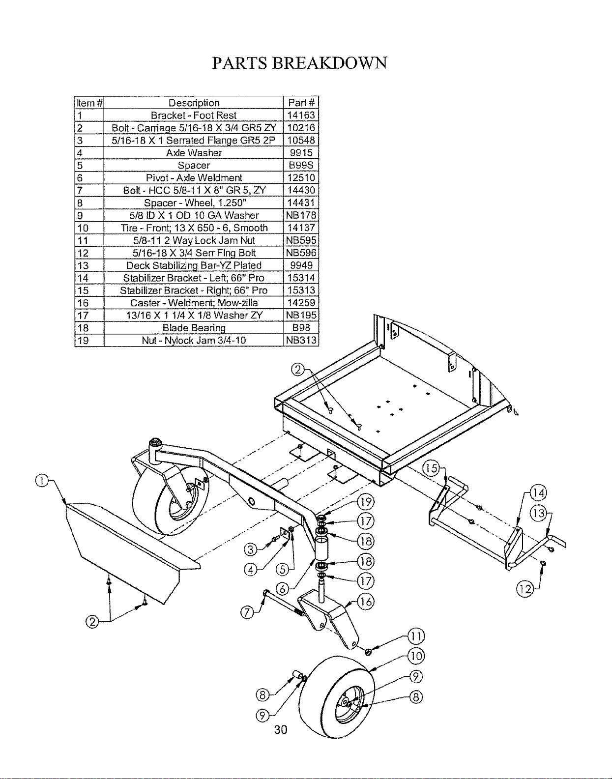
PARTS BREAKDOWN
Item #
1
2
3
4 Axle Washer
5 ...................... Spacer
6 Pivot - Axle Weldment
7 Bolt - HCC 518-1t X 8" GR 5, ZY
8 .......Spacer - Wheel, 1.250"
9...... 518 ID X 10D 10 GA Washer
DescdPti0n Part #
Bracket- Foot Rest 14163
.....Bolt- Carriage 5116-18 X 3/4 GR5 ZY, I ,102,1,#,,
5t16-18 X 1 SeEated E!ange GR5 2P , 10548
9915
B99S
12510
14430
14431
NB178
10 Tire X 6.50..'o6, Smootl_ .14 ! 37'
..... 518-11 2 Way Lock Jam Nut ..... N,B,59,#,
.!.2.... 5116-!..8 X 3/4 Serr Flng Bolt NB596
13 Deck Stab..i..!izingBar-YZ Plated 9949
t4 Stabilizer Bracket- Left; 66" Pro 15314
........... f ....
i5 Stabilizer Bracket- Right; 66" Pro 15313
16 Caster-..Weldment; Mow-zilla .14259
17 13116 X 1 1/4X 118WasherZY NB195
18 Blade Bearing B98
19 Nut - Nylock Jam 3/4-10 NB313
PARTS BREAKDOWN
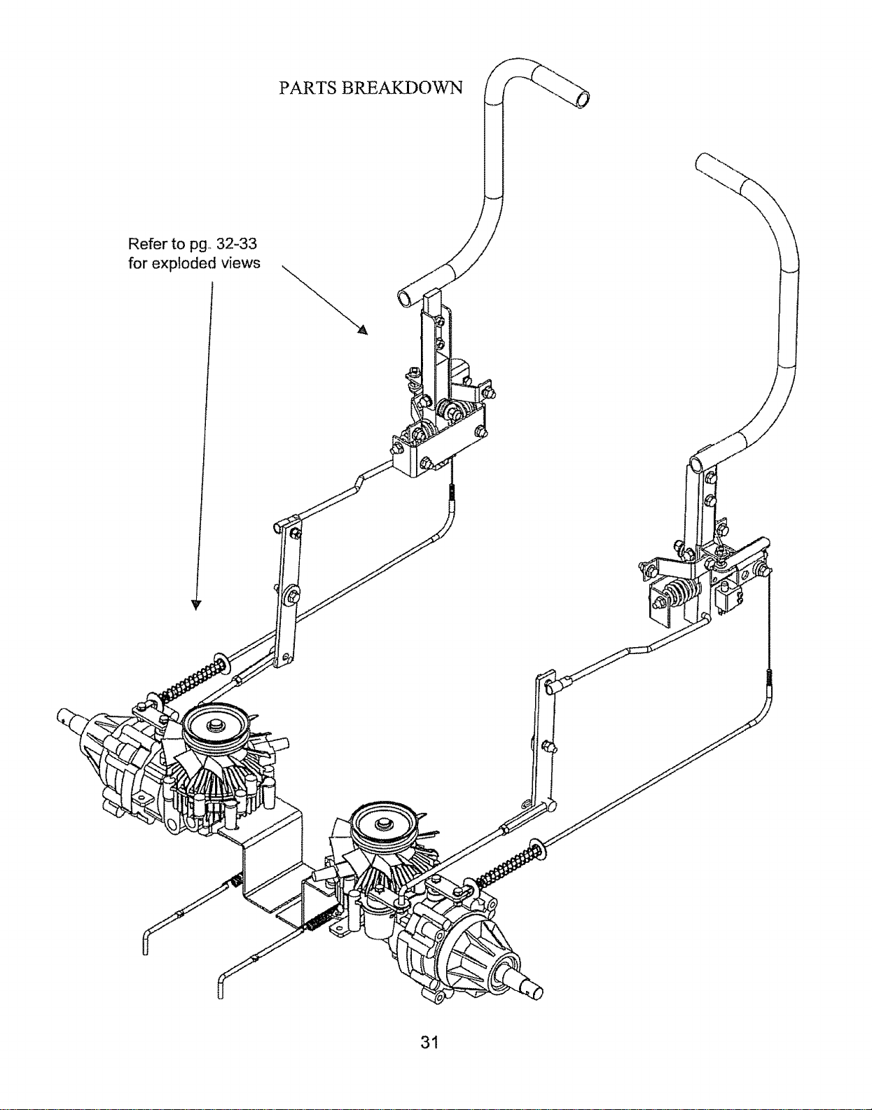
Refer to pg, 32-33
for exploded views
31
PARTS BREAKDOWN
i #1 D scOpUor, _Pa t#
1 , NUtll,llllNlYI!I0C318"16 ZY ........... NB182
2 WASHER 39--114G FLT 17X104
'3'' sP Washer Bellvl. PLN .413 X.945 X.1t8 NB607
4 WASHER, FLAT-DELRiN 17X21'7"
5 5/'16-i8 Serrated F_ingNut ZY NBI'7'0'"
6 !" Direct'ional'H'a'ndie weldment, Left - 1i769
7 Handle Pivot ..............9985
....................... i ,,,
8 5!!6_18 X 1 Serrated Flange GR5 2P : 10548
9 5/16 SAE Washer Z',€' NB275
10 Nut, Nyloc 5f16-18 ZY NB181
11 5/16-18 X314 Sen" Flng Bolt NB596
t2 5/16-18 X 1 Carriage Bolt GR5 10197
13 _ Safe!y Switch R0cker'Am_ ......... , 9925
I4 Spacer B99S
Item # Description Part #
15 5116-18 X t 1/4 serr...E!ng.Bolt zY.. NB253
16 5116 SAE Washer ZY NB275
17 1/4-20 Nylok Nut NB180
18 Nut, Nyloc 5f16-18 ZY NB'181 ........
i9 Clutch Cable Clevis T44CH 9023
20 1/4-20 X 3t4 GR5 ZY NB250
21 Contmf Arm 9986
......... =..............
22 Tapered Spdng ..... 3609
23 Bracket, 5.5" Neutral 10899
24 1" Directional Handle Weldment, Right 11768
32
PARTS BREAKDOWN
Item # Description ............... .......Part#
1 Linkage - Steering' 9" X 1+25" 14032
i ......
2 Connector 14028
3 Hydro Linkage Right Weldment 14058
4 Hydro Linkage Left Weldment 14060
'5....... Bolt - 114-28X 314GRh' ZY".... NB62O
6 Washer 2i/4" Bei:ie_iie ........... 14399
7 ' Pin 2 Hair; #39 (Ai55H')ZY S'id ...... NB'I?7'
8 Cable - Parking Brake, Assy _ 9976
9 Linkage - Shill : 9919
10 Bushing - Latch Pin 7839Z
11 Washer- SAE Flat 5116 ZY" NB275
t2 ' Pin - Cotter, 1!8 X'314 zY Std '"NB125
13 washer 2 Fender, 5ii6 × i it40D _ G_ i NB579
14 Spring +Parking Brake ..... 10536
Item # Description Part #
15 Clevis - Clutch Cable; T44CH 9023
i6 Nut- Nyl0ck 1i4:20 NB180
17 Hydro - Eaton RH W Reservoir 14134
i8 ............. Plate - Hydro Release 9924"
19 _/asher- SP Wa_ 5f16 X7110 X.006 GR 10544
20 ....... Screw 2 _read F0_ing 26)_16
21 s crew -. 312-18)(. 75 26x249
22 Spring ' FOr ldier A_ BRs6
23 Supp0_ 2 Hydro ..........................13082
24 + Handle - Hydro Release ........ 9923
25 Washer - SAE Flat 5f16 ZY nb275
26 Hydro 2 Eaton LH wiRese_ir 14135
33
TROUBLESHOOTING
PROBLEM CAUSE CORRECTION
=: I.. Out of fuel 1 FItl fuel tank
2. Engine not "choked" properly 2 Choked engine and attempt to restart
Engine Will +
3. Engine flooded 3 Wait several minutes before attempting to
Not Start restart.
4 Replace spark plug
4.. Bad spark plug
5 Clean or replace air filter
5. Dirty air fitter
6. Dirty fuel filter 6 Replace fuel filter
7. Water in fuel 7 Drain rue1 tank & carburetor, refill tank with
fresh gas and replace fuel filter
8 Loose or damaged wiffng 8 Check all wiring
9 Carburetor out of adjustment 9 See Engine Manual
10 Engine valves out of adjustment 10. Contact an authorized service center
11. Extreme cold conditions 11 See Engine Manual
12 Fuel shut off valves closed . 12_ Open
1 Bad spark plug 1. Replace spark plug
Engine Hard
2 Dirty air fluter 2. Clean or replace air filter
To Start 3 Dirty fuel filter 3+ Replace fuet f_lter
4 Weak or dead battery 4.. Recharge or replace battery
5 Carburetor out of adjustment 5. See Engine Manual
6 Engine valves out of adjustment 6 Contact an authorized service center
7 Loose or damaged widng 7 Check af] widng
8. Stale or dirty fuel 8. Drain fue_ tank & refill with fresh gasoline
1 Place handles in the out most position
Engine Will 1 Directional handles not in correct position
2 PTO engaged 2 Push PTO switch down
Not Turn Over 3 Weak or dead battery 3 Recharge or replace battery
4.. Blown fuse 4 Replace fuse]
5 Clean battery terminals - See battery section
5, Corroded battery terminals of this manua!
6.. Loose or damaged widng 6 Check aII widng
7. Faulty ignition switch 7 CheckJreplace ignition switch
8. Faulty solenoid 8 Check/raplace solenoid
9. Faulty operator presence swJtchtsv_tches 9. Contact an authodzed service center
=
Engine Clicks + Weak or dead battery 1 Recharge or replace battery
but Will Not 2 Corroded battery terminals 2 Clean battery terminals - See battery secfio
Start 3 Loose or damaged widng of this manual
4. Faulty sofenoid 3 Check all wiring
4., CheckJreplace solenoid
,,,,,,,,,,,,,,,,mlllll,ll,llllllmll iiii i ] I i I I i I I I I ,,,,,,,,,,,,,,,,,,,,,,,,,,,,,,
Unit Does not t incorrect tire pressure 1.. Check tire pressure (See Specifications)
Travel in a 2 Rear wheels rotating at different speeds 2 Adjust travel reduction weldment
straight line
1 Replace blade Tighten blade boil
1. Worn, bent or toose blade
Excessive 2 Replace blade driver
2. Bent blade ddver
3 Tighten Ioese part or parts. Replace
Vibration 3+. Loose/damage part or parts damaged parts.
4.. Faulty blade driver assembly 4 Replace blade ddver assembly
34
TROUBLESHOOTING Continued
PROBLEM
Loss of
Power
Engine
backfires when
CAUSE
I. Cutting too much grass/too fast
2 "Choke" position
3 Buildup of grass, leaves and trash under
deck.
4 Dirty air filter
5 Low oif levelldirty oil
6 Faulty spark plug
7 Dirty fuel filter
8 Stale or dirty fuel
9 Water in fuel
I0 Spark plug wire loose
t I Dirty engine air screenlfins
12 Dirtytc!ogged muffler
t 3 Loose or damaged wiring
t4 Carburetor out of adjustment
t5 Engine vafves out of adjustment
t6 Loose drive belt
turning engine
OFF
_===/======/Jl_
1 Worn, bent or loose blade
Poor cut -
2 Mower deck not leve_
uneven
3
4
5.
i 1
I
Poor cut - 2
uneven 3
4
5
1. Bad battery
Battery will =, Poorcabteconnections
not charge 3 Fa.,ysolenoid
1.
Loss of drive 2.
3
Engine throttle control not set at "SLOW"
position for 30 seconds before stopping
engine.
Buildup of debris under deck
Bent deck
Faulty Blade driver assembty
i i i ii i ii llLH HI
Worn, bent or loose biade
Mower deck not level
Buildup of grass. [eaves and trash under
deck
Bent deck
Faulty Blade driver assembly
Bypass linkages in the bypass position
Hydro belt worn, damaged, or broken
Idler spring loose or broken
CORRECTION
t Set in High Cut (position 8)traduce speed
2 Push choke control in
3 Clean underside of mower deck
4 Clean or replace air filler
5, Check oil level/change oil
6 Clean and re-gap or change plug
7 Replace fuel filter
8 Drain fuel tank & refill tank with fresh gas
9,, Drain fuel tank & carburetor, refill tank with
fresh gas and replace fuel filter
t0,, Connect and tighten spark plug wire
t 1.. Ctean engine air screenffins
12. Cleanlreplace muffler
t3,, Check all wiring
14,, See Engine Manual
15, Contact an authorized service center
16- Adjust idler/replace belt
I Move throttle control to "SLOW" position and
allow to idle for 30 seconds before stopping
engine
1
2
3
4
5
Replace blade, Tighten blade bolt
Level deck See section in this manual
Clean underside of mower deck
Replace deck
Replace blade driver assembly
ILIIIIILIILIIIII iii ILLLL i ljlljll LIIII
1 Replace blade Tighten blade belt
2 Level deck See section in this manual
3 Clean underside of mower deck
3
4 Replace deck
5 Replace blade driver assembly
1 Replace battery
2 Check/clean all connections. See section in
this manual
Replace solenoid
2
3.
Make sure that the bypass linkages are in
the drive or engaged position Located at
the rear of the machine.. Refer to decal on
the rear of the unit.
Replace Hydro belt
Replace Idler spdng
35

Mower Identification Unauthorized Replacement Parts
Each mower has its own model number,, Each
engine has its own model number° The model
number for the mower will be found under the
seat. The model number for the engine will be
found on the top of the blower fan housing.
All mower parts listed herein may be ordered
directly from Swisher Mower & Machine Co.
Inc,, or your nearest Swisher dealer,
All engine parts may be ordered from the
nearest dealer of the engine supplied with your
mower.
Use only Swisher replacement parts,,
The replacement of any part on this
unit with anything other than Swisher
authorized replacement part may
adversely affect the performance,
durability and safety of this unit and
may void the warranty. Swisher
disclaims liability for any claims or
damages, whether warranty, property
damage, personal injury or death
arising out of the use of unauthorized
replacement parts,,
WHEN ORDERING PARTS, PLEASE HAVE THE
FOLLOWING INORMATION AVAILABLE:
.Date Purchased
.Purchased From
-PRODUCT - ZT2766KP
-SERIAL NUMBER-
-MODEL NUMBER -
-ENGINE MODEL NUMBER -
TYPE -
•PART NUMBER WITH PAINT CODE
*PART DESCRIPTION
SWISHER MOWER & MACHINE CO. INC.
1602 CORPORATE DRIVE
P.O,, BOX 67
WARRENSBURG, MO 64093
Swisherinc.com
TELEPHONE - 1-800-222-8183
FAX- 1-660-747-8650
36

Replacement Parts
Quick Reference
Swisher Part #
AS069
037X66
14138
12527
125O9
14454
10540
10541
Part Description
Fuse !0 Amp
Belt Transmission
Tire - Rear; 23 X 10.5 - 12
137" Deck Belt
22,5 Mulching Blade
Belt- Engine to Deck
Blade Driver Assembly
(outside)
Blade Driver Assembly
(center)
CAUTION
Use extreme care when working on machinery.
Before performing any maintenance, turn off engine, allow the unit to cool & remove
the key. Disconnect spark plug wire,,
Set Parking Brake by placing the control handles in the neutral or outward position°
Do not wear watch or jewelry. Do not wear loose fitting clothes. Observe all
common safety practices with tools.
37

WARRANTY RIGHTS AND OBLIGATIONS
YOUR WARRANTY RIGHTS AND OBLIGATIONS: The California Air Resources Board and Swisher Mower, is pleased to
explain the evaporative emission control system (EECS) on your model year 2006 and later Swisher Product,, In California,
new Outdoor Power Equipment, must be designed, built and equipped to meet the State's stringent anti-smog standards,
Swisher Mower must warrant the EECS on your Power Equipment, for the period of time listed below provided there has
been no abuse, neglect, or improper maintenance_ For model year 2006 the EECS on your mower includes the liquid fuel
lines, fuel line connectors, and fuel line clamps,, Where a warrantable condition exists, Swisher Mower will repair at no cost
to you, Expenses covered under warranty include diagnosis, parts, and labor,,
MANUFACTURER'S WARRANTY COVERAGE: For a period of two years, any evaporative emission-related part included
in the list of EECS parts for your mower is defective, the part will be repaired or replaced by Swisher Mower_,
OWNER'S WARRANTY RESPONSIBILITIES: As the owner of this Power Equipment, you are responsible for performance
of the required maintenance listed in your owner's manual_ Swisher Mower recommends that you retain all receipts
covering maintenance on your Power Equipment, but Swisher Mower cannot deny warranty solely for the lack of receipts..
As the Power Equipment owner, you should be aware that Swisher Mower, may deny you warranty coverage if your Power
Equipment, or a covered part has failed due to abuse, neglect, or improper maintenance, unapproved modifications, or the
use of parts not made or approved by the equipment manufactureE You are responsible for presenting your Power
Equipment to an authorized Swisher Service center as soon as the problem exists.. Warranty repairs should be completed
in a reasonable amount of time, not to exceed 30 days. If you have a question regarding your warranty rights and
responsibilities, you should contact the Swisher Mower Service representative at 1-800-222-8183.
WARRANTY COMMENCEMENT DATE: The warranty period begins on the date the Power Equipment Is purchased.
LENGTH OF COVERAGE: This warranty shall be for a period of two (2) years from the initial date of purchase,,
WHAT tS COVERED: Warranted parts include the Liquid fuel line, fuel line connectors, and fuel line damps,
REPAIR OR REPLACEMENT OF PARTS: Repair or replacement of any evaporative warranted part will be performed at
no charge to the owner at an authorized Swisher Mower Service Center.. If you have a question regarding your warranty
rights and responsibilities, you should contact your nearest authorized service center or call the Swisher Mower Service
representative at 1-800-222-8183..
WARRANTY PERIOD: Any warranted part is not scheduled for replacement as required maintenance, or which is
scheduled only for regular inspection to the effect of "repair or replace as necessary" shall be warranted for two (2) years,
Any warranted part that is scheduled for replacement as required maintenance shall be warranted for the period of time up
to the first scheduled replacement point for that part,,
DIAGNOSIS: The owner shall not be charged for diagnostic labor that leads to the determination that a warranted part is
defective if the diagnostic work is performed at an authorized Swisher Service Center.
CONSEQUENTIAL DAMAGE: Swisher Mower, may be liable for damages to other engine or equipment components
caused by the failure of a warranted part still under warranty_.
WHAT IS NOT COVERED: All failures caused by abuse, neglect, or improper maintenance is not covered.
ADD-ON OR MODIFIED PARTS: The use of add-on or modified parts may be grounds for disallowing a warranty claim.
Swisher Mower is not liable to cover failures of warranted parts caused by the use of an add-on or modified part.
HOW TO FILE A CLAIM: If you have a question regarding your warranty rights and responsibilities, you should contact your
nearest authorized service center or call Swisher Mower Service representative at 1-800_222-8183,,
38
S VISI-IER I-IISTORY
Back before electricity came to rural Missouri Max Swisher was producing lawn mowers
from his mother's chicken house,. Max never liked to mow grass° He installed a gearbox on
his family's lawn mower creating a self-propelled unit_ By tying one end of a rope to the
mower and the other end to a tree in the center of the yard the mower circled the tree,
shortening the rope and guiding the mower in concentric circles. Max enjoyed relaxing under
a shade tree while his invention did all the work..
Max had designed his first self-propelled rotary lawn mower to do his dirty work for him..
Neighbors noticed his new invention and began asking him to make more,_ Today, over 60
years later', Swisher Mower and Machine Company, Inc, is still producing innovative lawn
and garden and ATV!UTV equipment designed to give us all more "relaxing in the shade"
time,,
Swisher products have been featured nationally on television programs such as Regis and
Kathie Lee and seen in publications like ATV Magazine, Country_ Journal, Popular Mechanics
Magazine and others.. In January 2000 Popular Mechanics Magazine named Max's zero
turning radius riding mower one of the 20 thcentury's top household inventions,.
Swisher offers value and function in its products to meet your grounds maintenance needs.
CELEBRATINGOVER60YEARSOFINNOVATION
1945-2008
39

your
oum!
Your Home
For expert troubleshooting and home solutions advice:
manage home
www,managemyhome°com
For repair - in your home - of all major brand appliances,
lawn and garden equipment, or heating and cooling systems,
no matter who made it, no matter who sold it!
For the replacement parts, accessories and
owner's manuals that you need to do-it-yourselfo
For Sears professional installation of home appliances
and items like garage door openers and water heaters.
1-800-4-MY-HOME ® 0-8oo-469-4663)
Call anytime, day or night (USA. and Canada)
www.s ears.corn www.s ears,ca
Our Home
For repair of carry-in items like vacuums, lawn equipment,
and electronics, call anytime for the location of your nearest
Sears Parts & Repair Service Center
1-800-488-1222 (US.A0 1-800-469-4663 (Canada)
www.s ears .com www.s ears .ca
To purchase a protection agreement on a product serviced by Sears:
1-800-827-6655 (US.A,) 1-800-361-6665 (Canada)
Para pedir servicio de reparaci6n
a domicilio, y para ordenar piezas:
1-888-SU-HOGAR ®
(1-888-784_,6427)
Au Canada pour service en frangais:
1-800-LE-FOYER Mc
(1-800-533-6937)
www.sears.oa
I'M _M
® Registered Trademark t Trademark I Service Mark o[ Sears Brands. LLC
® Marca Regislrada t Tu Marca de F6bdca t s_ Marca de Ser,4cio de Sears Brands, LLC
' Marque de commerce f _'_'_Marque d,_pos_e de Seals Brands. LLC © Sears Brands, LLC