Loading ...
Loading ...
Loading ...
ELECTRICAL POWER IS
REQUIRED TO OPERATE
COOKING SECTIONS WITH
GLOW BAR IGNITION. THE
OVEN AND GRIDDLE
BURNER(S) CANNOT BE
MADE TO OPERATE DURING
A POWER FAILURE.
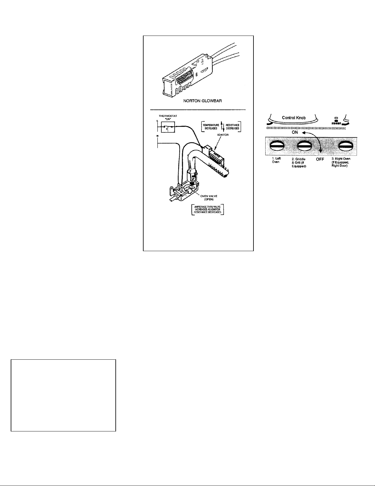
FIG. 13
SERIES IGNITOR/VALVE
CIRCUIT
GLOW BAR AND OVEN AND GRIDDLE IGNITION
System Operation
The glow bar ignition system consists of
four main components.
1. The thermostat control
2. The glow bar ignitor
3. The automatic valve (also called
the safety valve)
4. The manual valve
The thermostat, ignitor, and safety valve
are wired in a series circuit.
• When the thermostat knob is turned to a
selected setting, electrical contacts in the
thermostat close applying power to the
series ignition circuit.
• With power applied, the ignitor begins to
heat. Electrical resistance in the ignitor
will decrease as the temperature of the
ignitor increases.
• Electrical current in the series circuit
increases in proportion to the drop in
ignitor resistance.
• The glow bar ignitor limits the electrical
current in the circuit to 3.3 to 3.6 amps.
The surface temperature of the ignitor will
be between 1800° and 2500°F.
• When electrical current has reached the
proper amperage, the automatic safety
valve will open, releasing main burner
gas.
• The ignitor stays energized while the
burner is lit. Once the selected
temperature is reached, the thermostat
contacts will open and remove power from
the ignition circuit. The automatic safety
valve will close after a few seconds, and
the burner flame will go out.
Manual Shut-Off Valves
Each cooking section on the range that is
operated by glow bar ignition (gas oven, etc)
is under the control of a manual gas shut-off
valve.
Manual shut-off valves are located on the
underside of the control panel. Open the oven
door to access the slotted valve stems with a
flat blade screwdriver.
Depending on the particular features of your
FiveStar range, there may be one, two, or three
shut-off valves.
Manual shut-off valves will always be ordered
from left to right in the following manner:
1. Gas oven (left side on dual oven
models)
2. Griddle/Grill (if equipped)
3. Right gas oven (models 510 and 531,
right side door)
• To close the valve, use a flat
screwdriver to twist the valve stems
fully clockwise so the slot aligns
side to side as shown in the
underside view below.
• To open the valve, turn the stem
fully counter-clockwise so the slot
aligns front to back.
FIG. 14
CONTROL PANEL
UNDERSIDE
Note: On FiveStar cooktops, a
rectangular hole is located on the
underside of the control panel.
Reach up through this hole with the
screwdriver in order to access the
griddle shut-off valve.
Control Operation
Thermostat controls for sections
with glow bar ignition operate as
usual. Lightly press in the control
knob and turn counter-clockwise to
the desired temperature setting. An
indicator light will illuminate next
to the control knob whenever the
thermostat calls for heat.
Electrical Requirements
The differing electric systems on all
“-7” FiveStar range require more
power than standard ranges. Refer to
the range rating plate for the range’s
total amp rating and wiring
diagrams shown on pages 23-29.
8
Loading ...
Loading ...
Loading ...