Loading ...
Loading ...
Loading ...
INSTALLATION
Check the appliance is electrically safe and gas sound when you have nished.
30
470
350
675
A
315
All dimensions in millimetres
Gas inlet
Fig. 9.11
Fig. 9.12
Oven burner trim
Oven burner bracket
Repositioning Following Connection
If you need to move the cooker once it has been connected
then you need to unplug it and, having gripped under the
fascia panel and lifted the front of the cooker slightly
(Fig. 9.5), you need to check behind the cooker to make sure
that the gas hose is not caught.
As you progress, make sure that both the electricity cable and
gas hose always have sucient slack to allow the cooker to
move.
With a stability chain tted, release it as you ease the cooker out.
Do not forget to ret it when you replace the cooker.
When you replace the cooker, again check behind to make
sure that the electricity cable and gas hose are not caught or
trapped.
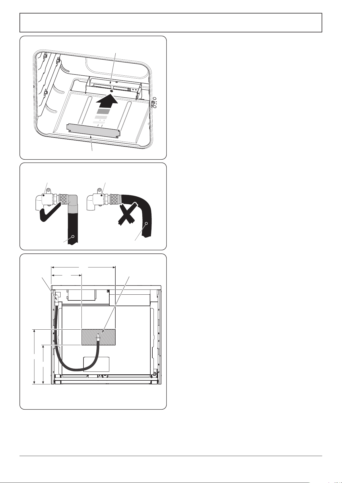
Fitting the Oven Burner Trim
The oven burner has an enamel burner trim. To t the trim,
simply hook it over the front of the oven burner bracket
(Fig. 9.10). Make sure that the burner trim is central to the
oven burner bracket.
Gas Connection
Must be in accordance with the relevant standards.
The gas supply needs to terminate with a down-facing
(Fig. 9.11) threaded tting ½” connection. The inlet
connector is located just below the hotplate level at the rear
of the cooker.
Because the height of the cooker can be adjusted and
each connection is dierent it is dicult to give precise
dimensions. Ideally, the house supply connection should be
in the shaded area (Fig. 9.12).
Means of isolation must be provided at the supply point by
either an approved quick-connect device or a Type 1 manual
shut-o valve.
The hose should be tted so that both inlet and outlet
connections are vertical so that the hose hangs downwards in
a ‘U’ shape (Fig. 9.12).
A exible connection is supplied with the cooker. If it is
necessary to use another hose it must be to AS 1869 Class B
and be suitable for your gas type.
If in doubt contact your supplier. Screw connect the threaded
end of the hose into the gas inlet.
After completing the gas connection, check the cooker is gas
sound with a pressure test. When checking for gas leakes do
not use washing up liquid – this can corrode. Use a product
specically manufactured for leak detection.
Natural Gas
The gas pressure regulator is present to give a nominal
pressure of 1 kPa on Natural gas. Connect to the Rp ½ inlet on
the underside of the pressure regulator.
Fig. 9.10
Flexible hose
PipeworkPipework
Flexible hose
Loading ...
Loading ...
Loading ...