Loading ...
Loading ...
Loading ...
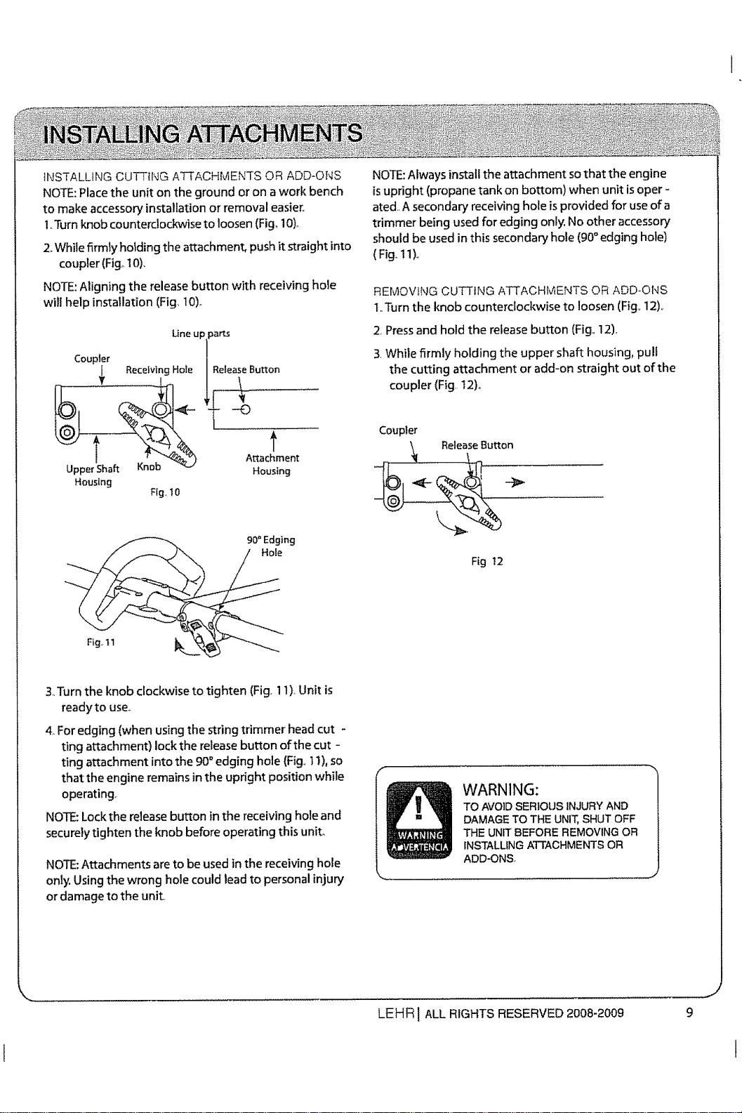
INSTALLING CUTTING ATTACHMENTS OR ADD-ONS
NOTE:Place the unit on the ground or on awork bench
to make accessory installation or removal easier,.
l o3brn knob counterclockwise to loosen (Fig, 10)o
2oWhile firmly holding the attachment, push it straight into
coupler (Fig_10),
NOTE:Aligning the release button with receiving hole
will help installation (Fig, 10)o
Lineup parts
Coupler
ReceivingHole | ReleaseButton
Upper Shaft Knob Housing
Housing
Fig, 10
90" Edging
NOTE:Always install the attachment sothat the engine
isupright (propane tank on bottom) when unit isoper -
ated. A secondary receiving hole is provided for use of a
trimmer being used for edging only. No other accessory
should be used inthis secondary hole (90° edging hole)
(Fig.. 11)o
REMOVING CUTTING ATTACHMENTS OR ADD*ONS
t,,Turn the knob counterclockwise to loosen (Fig,,12),
2, Pressand hold the release button {Fig,,12),
3,While firmly holding the upper shaft housing, pull
the cutting attachment or add-on straight out of the
coupler (Fig. 12)_
Coupler
ReleaseButton
\
Fig t2
&Turn the knob clockwise to tighten (Fig. 1I). Unit is
ready to use.,
4,For edging (when usingthe string trimmer head cut -
ting attachment) lock the release button of the cut -
ting attachment into the 90°edging hole (Fig.,1I), so
that the engine remains in the upright position while
operating.
NOTE:Lock the release button inthe receiving hole and
securely tighten the knob before operating this unit.
NOTE:Attachments are to be used in the receiving hole
only, Using the wrong hole could lead to personal injury
or damage to the unit
WARNING:
TOAVOIDSERIOUSINJURYAND
DAMAGETO THEUNIT,SHUTOFF
THEUNITBEFOREREMOVINGOR
INSTALLINGATTACHMENTSOR
ADD-ONS..
.............. J
LEHR I ALL RIGHTS RESERVED 2008-2009 9
Loading ...
Loading ...
Loading ...