Loading ...
Loading ...
Loading ...
8 www.dimplex.com
Fireplace Installation
3. Store the replace in a safe,
dry and dust free location until
you are ready to install the
replace.
Wiring
WARNING: To reduce the risk
of re, electric shock or injury to
persons, always use a licensed
electrician.
WARNING: Ensure that the
circuit on which the replace is to
be installed has the power cut off
at the service panel until installa-
tion is complete.
1. Carefully remove the electrical
cover bracket from the back of
the replace by removing the
three retaining screws. (Figure 2)
2. Leaving a minimum of 3 in.
(7.6 cm) of slack, route the
power supply through a cable
clamp (not included) and the
hole in the electrical cover
bracket.
3. Remove the two covers off of
the unit at the front to access
the wire connections. (Figure 3)
For 120V Installations
Use two conductor, non-metallic
sheath cable with ground wire
(3 wires total) for the incoming
power supply.
CAUTION: Use the appropri-
ate wire to meet local and
national electrical codes for
rated power consumption.
• Connect the L1 wire from the
unit to the live wire from the
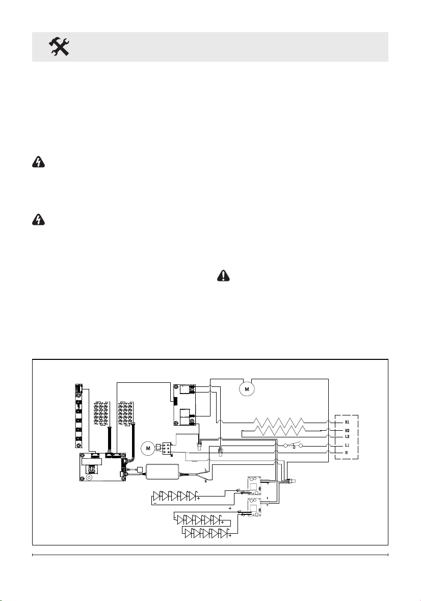
Wiring Diagram
AC/DC
ADAPTER
RELAY BOARD
SWITCH BOARD
DISPLAY / CONTROL BOARD
THERMISTOR
LED STRIPS
(RGB) - MEDIA
FLAME LED STRIPS (AMBER)
CUTOUT
THERMAL
FLICKER MOTOR
BLOWER MOTOR
LED STRIPS
(RGB) - FLAME
M
M
ELEMENTS
LED DRIVER
BOARDS
Loading ...
Loading ...
Loading ...