WOODSTOCK SOAPSTONE STOVES
OWNER’S MANUAL
PROGRESS HYBRID
MODEL 209a
Woodstock Soapstone Company, Inc.
66 Airpark Road, West Lebanon, NH 03784
Toll Free 1-800-866-4344 • www.woodstove.com
Rev 0221
Tested To UL 1482-2011 7th Edition
Listed By PFS Corporation
Tested and Listed by

OUR PROMISE
We are sure you will enjoy your new stove. During the first six months that you own
it, test its performance and experience the comfortable warmth of soapstone. If you
are not thoroughly delighted with the beauty, quality, and energy efficiency of your
stove, you may return it for a full refund, including the cost of return freight. This is
the best consumer protection plan in the industry.
EPA APPROVAL
This Manual describes the installation and operation of: the Model 209a Progress
Hybrid Catalytic Soapstone Stove
Model 209a Progress Hybrid Catalytic Soapstone Stove meets the U.S.
Environmental Protection Agency’s emission limits for wood heaters sold after May
15, 2020. When tested with cord wood, this stove has been shown to deliver heat at
rates ranging from 13,149 to 47,220 BTU/hr., and average emissions of 0.63 grams/hr.
The Progress Hybrid contains a catalytic combustor, which needs periodic inspection
and replacement for proper operation. It is against the law to operate this woodstove
in a manner inconsistent with the operating instructions in this manual, or if the cat-
alytic element is deactivated or removed.
This wood heater has a manufacturer-set minimum low burn rate that must not be
altered. It is against federal regulations to alter this setting or otherwise operate this
wood heater in a manner inconsistent with operating instructions in this manual.
LISTING TO UL #1482
Model 209a Progress Hybrid Catalytic Soapstone Stove has been tested to UL
Standard #1482 7th edition 2011 for safety, and listed by PFS Corporation. UL
Standard #1482 is the standard for testing solid fuel heating appliances which is uni-
versally recognized by all national building regulatory agencies (SBCC, BOCA, ICBO)
and individual states.
Please Note: Tested and Listed for US installations only
LIMITED WARRANTY
Your Woodstock Soapstone Stove will be carefully inspected before shipment. We will
replace any part which is defective in material or workmanship, free of cost, for a peri-
od one year from the date of purchase. If a defect is discovered, please contact
Woodstock Soapstone Company, Inc. for instructions regarding return or replacement
of the defective part.
CATALYTIC COMBUSTOR
WARRANTY
The catalytic combustor in your Progress Hybrid Woodstove is fully warranted for
three years from the date of purchase against any defect in workmanship or materials
that prevent the combustor from functioning when installed and operated properly.
The catalytic combustor is additionally warranted for three years from the date of pur-
chase for any deterioration in the stainless steel substrate material. For instructions
regarding return or replacement of the catalytic combustor, please contact:
Woodstock Soapstone Company, Inc.
66 Airpark Road
West Lebanon, NH 03768
Phone: 1-800-866-4344 • Web: www.woodstove.com
Tested and Listed by

MODEL 209a
PROGRESS HYBRID CATALYTIC
TABLE OF CONTENTS
WARRANTY INFORMATION/CERTIFICATIONS............ Inside Cover
EPA Certification, UL Listing, Warranty, Catalytic Combustor Warranty
INTRODUCTION
Progress Hybrid Wood Stove Explained
INSTALLATION......................................... .............. 1-14
Installation, Location, Chimneys, Fireplace InstallationClearance Table, Wall
Protection, Floor Protection
OPERATION............................................................15-20
Setting up Your Stove, Seasoning Your Stove, Starting a Fire and Establishing
Draft, Engaging the Catalytic Combustor, Re-loading & Overnight Burning,
Ash Removal, Surface Thermometer, Overfiring, Daily Use, The Fall-Away
Handle, Firewood
CATALYTIC COMBUSTOR........................................ 21-24
How your Combustor Works, Inspection & Cleaning, Replacement, Catalytic
Probe Thermometer, Frequently Asked Questions, Catalytic Combustor
Warranty Information
MAINTENANCE..................................................... 25-27
Stove, Stone & Glass Cleaning, Gasket Replacement, Routine Checks, End-Of-
Season Maintenance, Creosote
TROUBLESHOOTING............................................... 28-29
SAFETY................................................................. 30-31
Overview, Installation, Smoke & The Chimney, Heat, Ash Removal,
Precautions, Emergency Procedures
PARTS LIST & DIAGRAMS......................................... 32-35
SPECIFICATIONS................................................... Back Cover

Introduction
In many ways, the Progress Hybrid was inspired by our customers’ request for a larger wood stove
capable of heating large spaces. Many wanted the choice of top or rear venting and right or left side
loading. A large ash pan option also made the list. Of course everyone wanted a grand view of the mes-
merizing flames. All of these features made it into the final design, but this was not good enough for us.
We wanted this new wood stove to exceed the efficiency of any stove in production and deliver its soul
soothing warmth with one of the most efficient burns, and lowest emissions in the industry. How could
we achieve these goals? Hybrid technology.
Why is the Progress called a Hybrid? It is a hybrid because it combines two distinct and proven com-
bustion technologies to achieve our goals of high efficiency and low emissions. Government regulations
and increased public concern regarding air quality over the past few decades have led the wood stove
industry to develop cleaner burning stoves. These stoves have used either catalytic combustors or a sec-
ondary combustion system- until now. The Progress Hybrid is the first wood stove in the industry to
combine these two systems and reap the benefits of both to produce one of the cleanest burning and
most efficient stoves available today. Each system on its own has distinct advantages. A brief description
is below followed by a more detailed explanation.
Catalytic Combustors:
• Burn wood smoke starting at 500° F
• Operate best at low to moderate burn rates
• Yield clean, efficient, long duration burns
• Add to wood stove efficiency by generating heat from burning wood smoke
Secondary Combustion Systems:
• Burn wood smoke starting around 1000° F
• Operate best at moderate to high burn rates
• Deliver maximum heat output
• Provide a very active fire that is great for viewing
Catalytic combustors are well suited for longer duration, moderate burning. They have the ability to
break down the organic compounds in wood smoke at lower temperatures. This leads to a cleaner burn
than older stoves that allowed the wood to smolder when choked down for longer burn times. The cat-
alytic reaction reduces harmful combustion by-products to mainly water vapor and carbon dioxide. As
the compounds are broken down through this reaction a substantial amount of heat is released as well.
This extra heat increases the overall efficiency of a catalytic wood stove. The combustor has the ability to
take advantage of the fuel value of the wood smoke before the smoke leaves the stove as pollution and
wasted energy.
Secondary combustion systems are designed to maximize efficiency and reduce emissions as well, but
they operate differently. The secondary combustion system incorporates a secondary air source to ignite
the volatile gases produced by the wood burning in the firebox. This reaction requires temperatures over
1000 degrees F to effectively start breaking down the organic compounds in the wood smoke. Secondary
combustion systems will work best in a stove that is designed to maintain high firebox temperatures
and allow the right amount of secondary combustion air into that high temperature area. The gases burn
at very high temperatures as the smoke is broken down into simpler compounds in the firebox.
The Progress Hybrid incorporates a large catalytic combustor as well as a secondary combustion sys-
tem. It has been designed to deliver the maximum amount of heat from the wood and smoke it burns
while minimizing the pollution released to the atmosphere. One simple lever controls the flow of pri-
mary as well as secondary air into the firebox. The amount of air, temperature of the firebox, and the
amount of fuel (smoke and gasses) present will dictate which system (or both) is most active. Simply
allowing more air into the firebox will generate more heat there, while also increasing the amount of
oxygen to light off the secondary combustion process. The result is a spectacular light show as the sec-
ondary flames swirl and tumble around the firebox. The entire stove body will radiate warmth for
hours. Less air to the firebox will slow the primary combustion, and create the ideal conditions for an
effective catalytic reaction. The catalytic combustor will become very active as the smoke and oxygen not
consumed in the firebox will provide it with the necessary ingredients to effectively break down the
compounds in the smoke, and generate substantial heat at the top of the stove. Heat will be delivered to
your home very evenly and moderately for twelve hours or more.
These two systems are not mutually exclusive and have been designed to work together. The Progress
Hybrid is designed to utilize each system or both depending on the conditions present in the firebox.
This makes operating the Progress as simple as possible while providing a clean and efficient burn over
a wider range of heat output.
This hybrid design makes the Progress the perfect marriage of modern combustion technology and the
timeless beauty and function of soapstone.
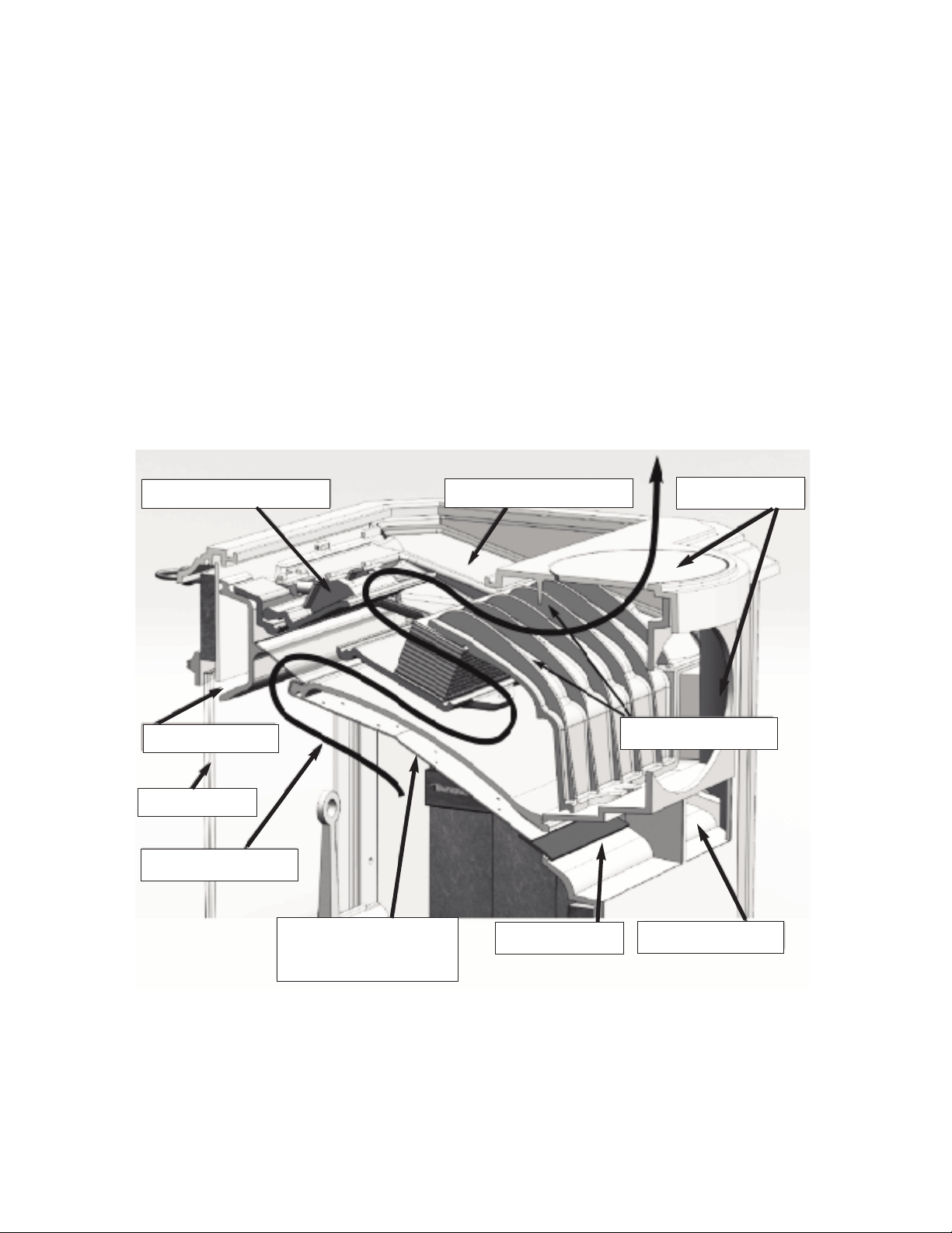
Catalytic Bypass Damper
Top or Rear Vent
Secondary Inlet
Stainless steel fireback,
perforated air inlets for
secondary combustion.
Primary Air Wash
Double Glass
Right Primary Inlet
Heat Exchange Fins
SMOKE EXIT PATH
Primary Air Manifold
INSTALLATION
For over two centuries, New Englanders have heated their homes with soapstone stoves. A properly in-
stalled and operated soapstone stove will warm your home and delight your eye for a lifetime.
Read this entire manual carefully. It explains how to install your Woodstock Soapstone Progress Hybrid
Wood Stove safely and how to operate it correctly and efficiently. The clearances and procedures
recommended in this guide are in compliance with the recommendations of the National Fire Protection
Association (NFPA), the Underwriters Laboratories (UL), and the U. S. Environmental Protection Agency
(EPA). You may feel some of them are very stringent, but they should be followed. They were designed to
protect you, your home, and the environment. Improper installations are a major cause of serious fires.
Failure to follow instructions may result in property damage, bodily injury, or death.
Before installing a woodstove, check your local building codes and any requirements established by your
insurance company.
You may need a local building permit to install your stove. Any changes in your home must comply with
building codes. If the codes have not been fully updated, you may want to check with the Building
Inspection Department or your local Fire Department. A qualified stove installer should be aware of any
changes and updates to local and state codes and may be best suited to handle
your installation work.
Many chimney sweeps are qualified installers. If you are unfamiliar with
sweeps or need to locate a certified sweep in your area, you can check listings at
www.csia.org (Chimney Safety Institute of America). Builders and contractors
are another option. In some cases, homeowners install their own stoves. Before
installing your stove, please review carefully the stove installation, clearance,
and safety information in this manual. Woodstock Soapstone has NFI (National
Fireplace Institute) certified woodburning specialists on staff and available to
answer any questions you may have about your installation. If you have
questions, please call us toll free at 1-800-866-4344.
You should notify your insurance company that you are using a woodstove.
Before you light your first fire, have a local building inspector and your
insurance representative inspect, and approve in writing, your installation.
THE PROGRESS HYBRID IS NOT APPROVED FOR INSTALLATION IN MOBILE HOMES.
LOCATION
A stove which is centrally located will heat the greatest area of your home. Heat should be able to circulate
easily into nearby rooms. Placing your stove near an open stairway or register in the floor will help transfer
heat to other rooms.
Other installation considerations are:
•Clearance to Combustibles
•Adequate Space for Wood Loading and Ash Removal
•Room Traffic Patterns
Most people install their stove in a room they use frequently where they can enjoy the beauty and comfort
of the stove. This also helps in ease of the monitoring and reloading the stove as needed.
A well-planned placement will enhance your enjoyment of your stove and may save installation costs.
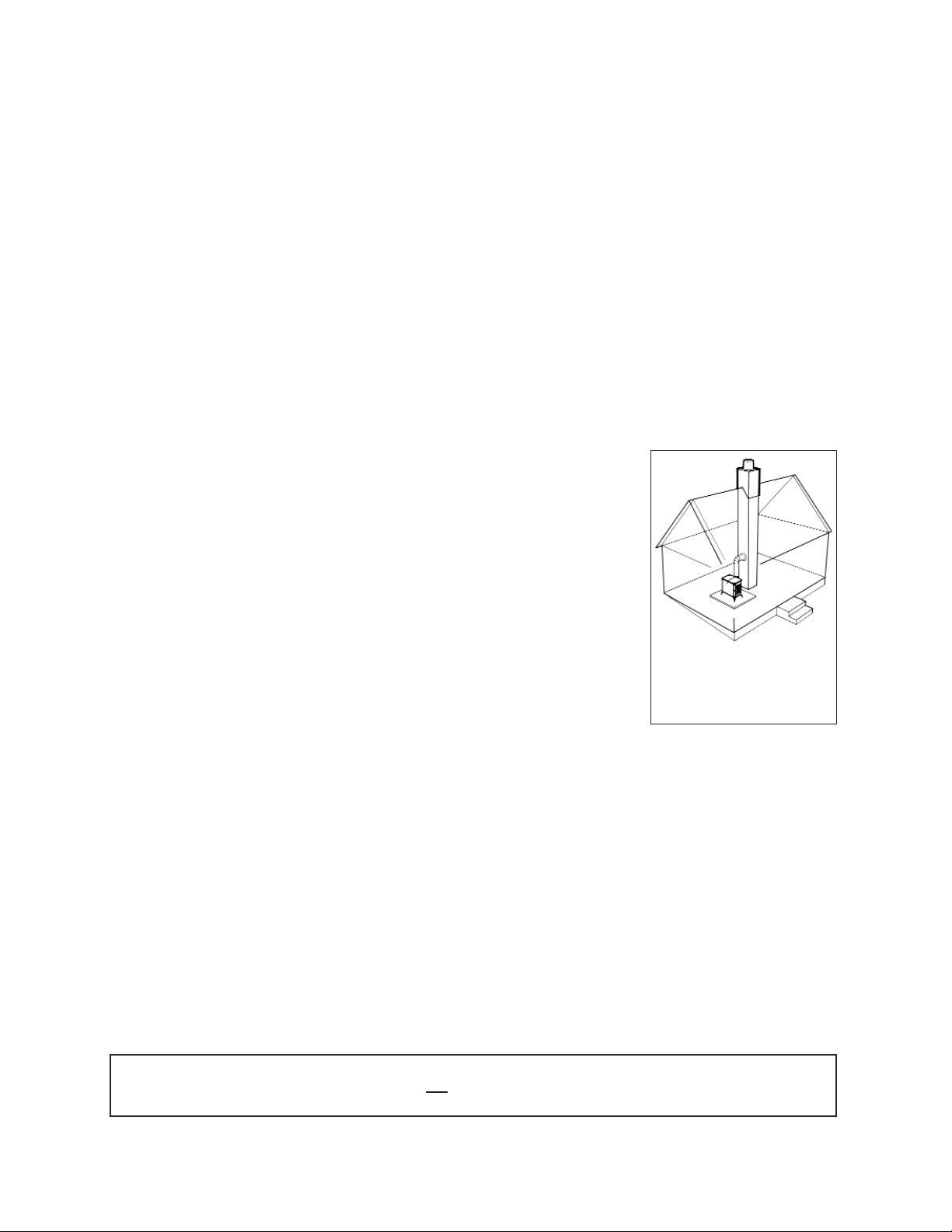
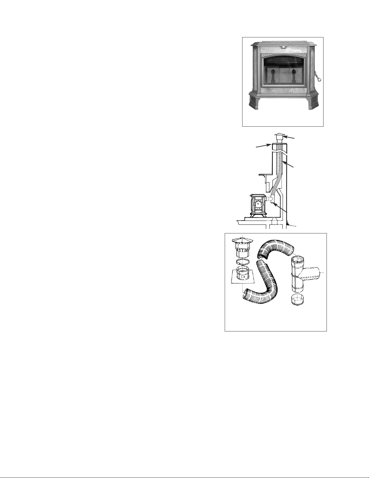
The best location for a chimney and
woodstove is in the center of the
house. The chimney will be warmer,
draft will be better, and radiant heat
will be distributed more evenly.
ALCOVE INSTALLATIONS
The Model 209 Progress Hybrid Woodstove is not approved for an alcove installation. An alcove is described
as an area less than 512 cubic feet, which is equivalent to an 8’x8’x8’ space.
1
CHIMNEYS
Your chimney is a critical component of your wood heating system. A prop-
erly designed and constructed chimney will help to provide safe and efficient
woodstove operation. Hot exhaust rising up through the chimney also pulls
combustion air into the stove through the air damper. If a chimney is too short,
or the flue too large, the hot exhaust will cool and slow down. This can lead to
poor stove performance, smoke spillage, back puffing, and even creosote build
up in the chimney itself. An excessively tall chimney could lead to a strong
draft, which may make the fire difficult to control with the stove damper. This
could result in over firing the stove and lead to damage to the cast iron compo-
nents as well as the catalytic combustor. Whether you are installing a new
chimney, or adapting an existing chimney to your woodstove, close attention
to chimney height, flue size, and location should be considered.
Chimney Flue Sizing:
The ideal flue size for the Progress Hybrid is 6” - the same diameter as the
stove’s flue collar.
If upsizing needs to occur due to an existing chimney the following general
rules apply:
1. Interior Chimney (no walls of the chimney exposed to the outside below
the roofline): the inside cross-sectional area of your chimney should be no more than 3x the cross-sectional
area of the woodstove flue collar.
2. Exterior Chimney (if there are one or more walls exposed to the outside below the roofline) - The flue
should be no more than 2x the cross-sectional area of the flue collar.
Recommendation: The Progress Hybrid has a 6 inch flue collar, thus an 8 inch x 10 inch rectangular or 10
inch round flue tile for an inside chimney are the maximum flue sizes we recommend for this stove. For an
outside chimney, an 8 inch x 8 inch square or 8 inch round would be the largest acceptable. The smallest size
we recommend is 6 inches round, as the flue should not be less than the flue collar
size.
Note: For flues that exceed the recommended area, a stainless steel chimney liner is rec-
ommended.
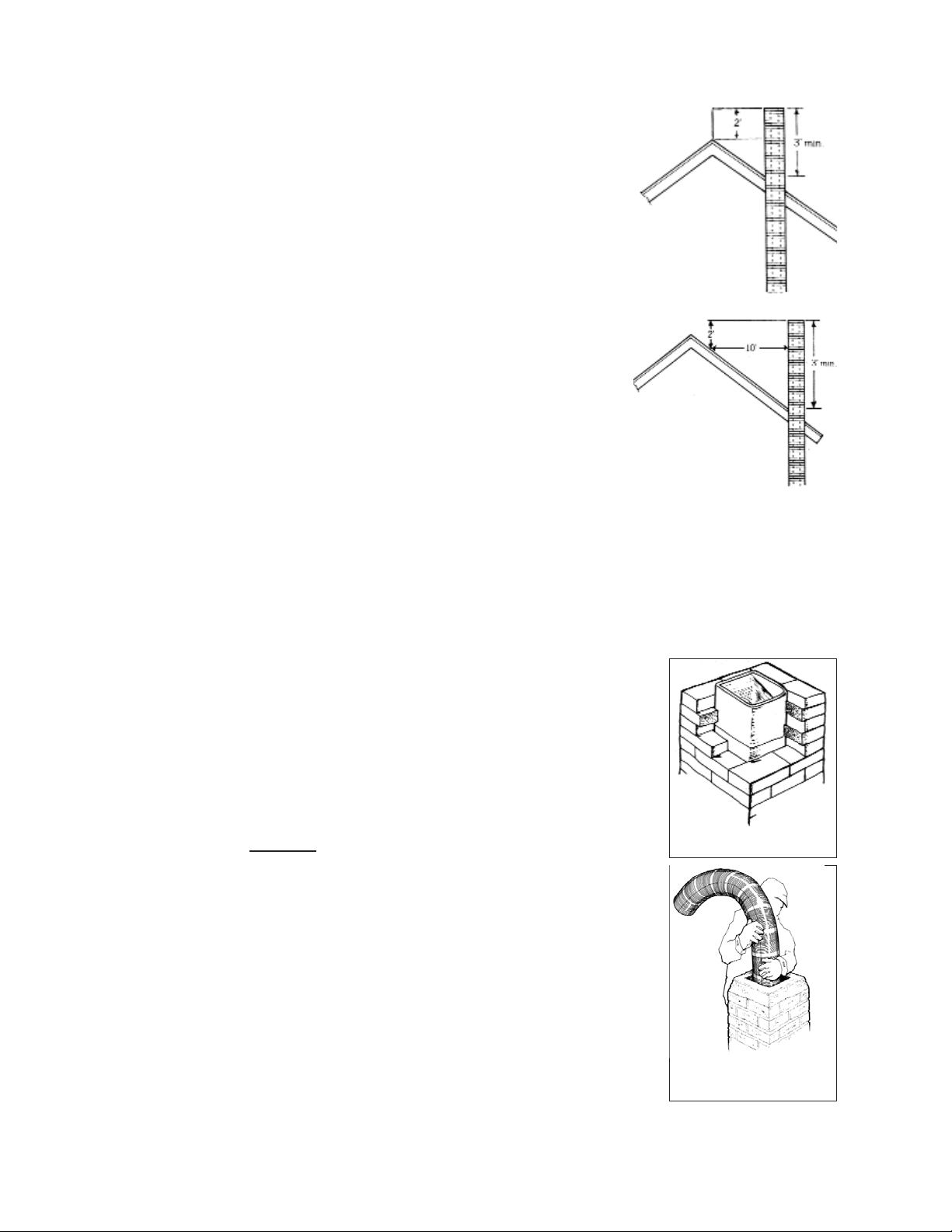
Height Requirements:
The chimney must extend 3 ft. above the point where it passes through the roof
and must also be 2 ft. higher than any roof surface or obstruction within 10 feet
(measured horizontally) of the chimney. You should check your local building codes
for any other requirements.
The recommended minimum chimney height is 15 feet from the flue collar of the
stove to the top of the chimney. This includes connector pipe and chimney pipe.
There may be other factors to conform to code for clearances on the roof, high wind,
high altitude, etc., that may make the minimum height undesirable or a violation of
building codes.
CHIMNEY TYPES
DO NOT CONNECT THIS UNIT TO A CHIMNEY FLUE SERVING AN-
OTHER APPLIANCE.
There are two acceptable types of chimneys: Lined Masonry Chimneys and Class
A, Pre-fabricated Metal Chimneys rated to 2100° F. Masonry chimneys must meet
all applicable codes for a safe installation.
Chimneys must ex-
tend a minimum of
3’ above roof
penetration...
... and a minimum of 2’
above the highest point
within 10’.
Installing a Stainless
Steel Liner in a Masonry
Chimney
Terra Cotta Tile Lined
Masonry Chimney
2
Lined Masonry Chimneys:
Always have the chimney inspected prior to your stove installation. If your
chimney is not lined with appropriately sized clay flue tiles, or the clay tiles are
old, cracked, damaged or otherwise compromised, a stainless steel chimney
liner or poured liner will be required. Depending on the condition of your flue
or clay tiles, the stainless steel liner may need to be wrapped in a high tempera-
ture insulation blanket. A liner may also be recommended if your flue is too
large for the draft to flow properly (please refer to the section on chimney siz-
ing). Our customer service department can answer any questions regarding the
use of a liner and/or insulating blanket. Call 1-800-866-4344.
Existing chimneys should be checked twice a year for obstructions, cre-
osote deposits, surface cracks, chemical deterioration and poor construction.
Any damage should be repaired immediately. Two other chimney related
areas that should be checked are chimney penetrations at the floor or ceiling
joists, and at the roofline. There should be at least 2 inches of clearance be-
tween the chimney and floor joists or other combustible materials. Poor
flashing between the chimney and the roof line can cause leaks and deterio-
ration of chimney mortar.
You should make preliminary checks, but if you have any doubts, or are
unfamiliar with chimney construction, cleaning, or maintenance, have a
local fire official or certified chimney professional inspect your chimney. If
repairs are required, be sure to use someone who is knowledgeable in chim-
ney work and familiar with local code requirements.
In addition: All brick or cinder block chimneys should have clean out ac-
cess with a tight fitting door. Masonry chimneys should have a wash at the
top. All chimneys should have a cap to keep out rain and snow and to mini-
mize downdrafts caused by wind.
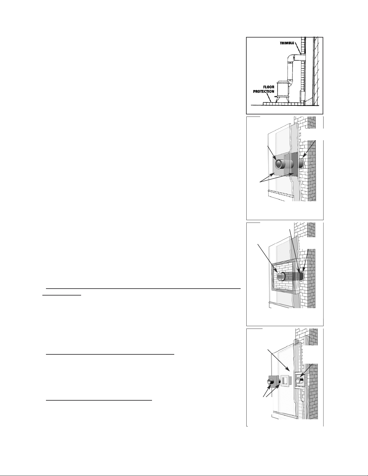
Passing Through A Combustible Wall:
With an exterior chimney, in most cases the chimney connector (or stove
pipe) will need to pass through a combustible wall. The following are
acceptable methods:
A. Use a section of Solid Insulated Prefabricated Metal Chimney to connect
to the chimney - Use a section of insulated prefabricated 2100° Class A
chimney pipe listed to UL 103 HT (at least 1” of insulation or greater) the
same inside diameter as the stove pipe and maintain a 9” air space between
the wall of the prefabricated chimney and the combustible wall. This section
of chimney pipe can be supported by a sheet metal plate securely fastened to
the combustible wall, with a hole cut in the middle of it. This will close the
gap around the chimney pipe and the framed opening. (See Diagram A
Below)
B. Build a solid brick surround around a tile liner - Frame a 3.5” thick brick
surround into the combustible wall you need to pass through. Maintain a
minimum 12” brick separation from the clay liner to combustibles. The
minimum 5/8” thick clay liner should be cemented in place and run from the
outer surface of the brick to the inner surface of the chimney. (See Diagram B
Below)
C. There are also UL Listed kits available that are specifically designed for
passing through a combustible wall. For more information on these kits,
please contact Woodstock Soapstone Company. Please note: there are several
UL listed wall pass through kits available, always follow the manufacturers
specific installation instructions. (See Diagram C Below)
3
A.
Using a Prefabricated Metal Chimney sec-
tion to connect to an existing masonry
chimney located behind a combustible wall
Refractory
Cement
Insulated
section of
factory built
chimney
Sheet
Steel
Supports
9”
9”
9”
9”
The minimum clearance for a single wall
metal stovepipe and terra cotta thimble at
the chimney connection is 12”
B.
Refractory
Cement
12”
12”
12”
12
Stainless Steel
Connector
Fireclay Thimble
UL listed and approved wall pass thru kit.
C.
UL listed
insulated
thimble
Minimum required
air space
Listed wall
protector &
cover shield
Connecting the stove to a masonry thimble.
For other methods, please refer to NFPA 211.
REMEMBER, UNPROTECTED SINGLE OR DOUBLE WALL STOVE PIPE SHOULD NOT PASS THROUGH A COMBUSTIBLE
WALL OR CEILING TO CONNECT TO THE CHIMNEY
. YOU MUST USE AN APPROVED METHOD WHICH PROVIDES
GREATER PROTECTION THAN SINGLE OR DOUBLE WALL PIPE
.
Prefabricated Metal Chimneys:
For high efficiency, freestanding woodstoves, like your Woodstock Soapstone stove, a
Prefabricated Metal Chimney must be listed as Class A and carry a UL Listing of 103 HT
(high temperature). The “UL 103 Type HT Class A” prefabricated
chimney will have a temperature rating of 2,100° F.
There are prefabricated chimney systems that are approved to 1,700° F and are generally
used with fireplace inserts or
factory built fireplaces. These ARE NOT suitable for use with your Woodstock Soapstone stove.
At the point of the first penetration of a combustible surface (i.e., wall or ceiling) all subsequent venting
components need to be prefabricated “UL Type HT Class A”. If your prefabricated chimney goes through
a living space it must be enclosed, and that enclosure must conform to clearance standards for the prefab-
ricated chimney. Your chimney must pass through your roof and extend above the roof line in accordance
with code standards. Please refer to height requirements on Page 2.
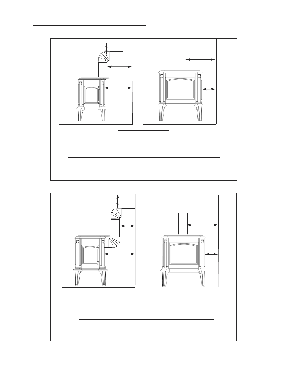
PREFABRICATED CHIMNEY CONFIGURATIONS
The diagrams below represent the most common and acceptable installations using prefabricated chim-
ney pipe. The necessary components are listed and shown in their appropriate locations. These compo-
nents are Class A listed to U.L. 103HT (tested to 2100 degrees F.) Only components listed to U.L. 103HT
can be used to install your wood stove. Installation instructions are described below for examples only.
More detailed instructions are available through Woodstock Soapstone or the pipe manufacturer. AL-
WAYS FOLLOW THE MANUFACTURER’S SPECIFIC INSTALLATION INSTRUCTIONS.
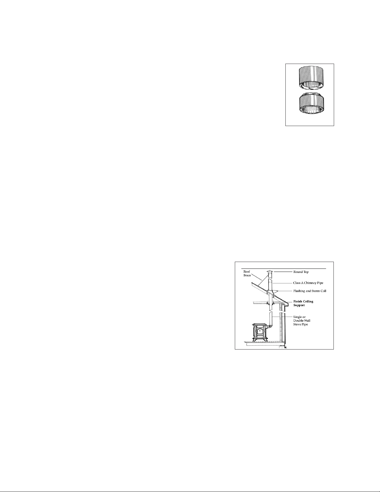
Installtion 1- Flat ceiling through the roof
First, determine where the stove will be placed. Pay close attention
to all required clearances for the stove and connector pipe. Next, use
a plumb line to locate the Finish Ceiling Support in the ceiling above.
Cut the appropriate sized hole in the ceiling and frame in the neces-
sary supports to secure the ceiling support. Install the pipe adapter
onto the first section of chimney pipe, and lower them into the Ceil-
ing support. Use an insulation shield in the attic to keep any insula-
tion away from the pipe. If the attic is a living space the chimney pipe
must be fully enclosed. As the pipe extends through the roof, install
the appropriate flashing and storm collar to keep the weather out. As
the height of the chimney increases to meet code, it may be necessary
to install a roof brace (typically recommended at 5’ intervals). All
chimneys should have the appropriate cap installed at the top to re-
duce wind and weather related downdrafts as well as deter any ani-
mals from building nests. The connector pipe should extend from the flue collar of the stove to the pipe
adapter at the ceiling support. The male (crimped) end should always point down toward the stove. Be
sure that each joint has enough overlap for a secure connection. All connections should be fastened with
screws, including at the flue collar and pipe adapter. (Please refer to the manufacturers full set of installa-
tion instructions)
Installation 2- Pitched/Cathedral Ceiling through the roof
Determine where the stove will be placed. Be sure all clearance requirements are satisfied. Choose the
appropriate support for your installation (Support box or Roof support package). Use a plumb line to lo-
cate the support in the ceiling above. Cut the appropriate sized hole in the ceiling and install the neces-
sary framing to secure the support. Install the support according to its specific instructions.. Be sure that
4
UL 103 HT Stainless
Chimney Connection
Installation 1- Flat ceiling through the roof
Attic Insulation Shield
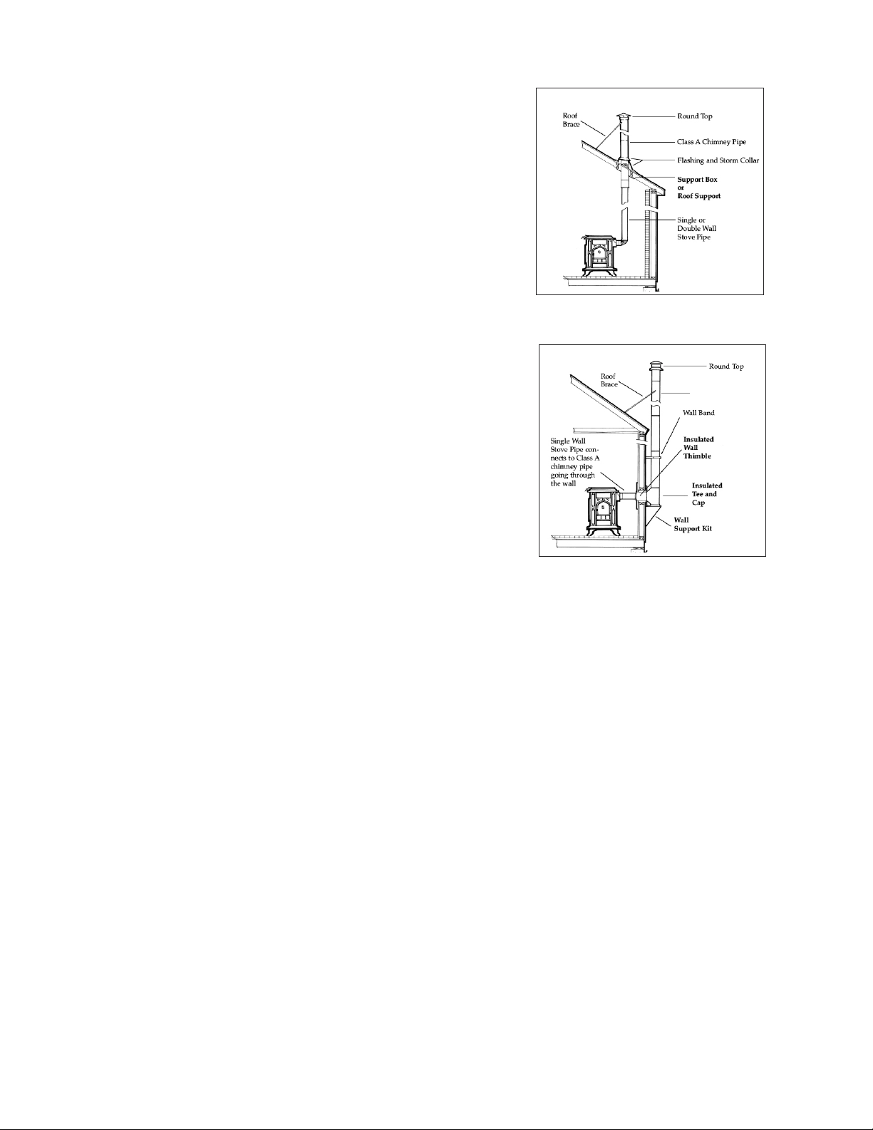
the support hangs down below the ceiling far enough to maintain
proper clearance to the connector pipe (steeper slopes require more
pipe below the ceiling). Install the pipe adapter to the first section of
chimney pipe and lower it into the support box (or connect it to the
bottom of the roof support). As the pipe extends through the roof
install the appropriate roof flashing and storm collar. Install the
proper chimney pipe lengths to meet code and recommended chim-
ney height. It may be necessary to install a roof brace for stability.
Always install the appropriate cap to the top of the chimney. Dou-
ble wall connector pipe is recommended for installations that have
10’ or more from the stove to the chimney. Be sure that all joints in
the connector pipe are secure and fastened with screws, including at
the flue collar and chimney pipe adapter. (Please refer to the manu-
facturers full set of installation instructions).
Installation 3- Through the wall
This installation requires the use of an insulated wall thimble to
penetrate a combustible wall. Typically a 9”-12” chimney pipe and
pipe adapter will pass through the thimble and make the connection
between the interior connector pipe and an insulated tee with a
clean out on the outside of the bulding. The tee and chimney rising
up from it rest on a wall support designed to bear the weight of the
chimney. Install lateral supports as specified as the chimney rises
along the exterior wall. The appropriate flashing and storm collar
should be installed if the chimney penetrates an eave or overhang.
An offset of 15 or 30 degrees may also be used to go around an over-
hang. As the chimney extends above the roof to meet code it may be
necessary to install a roof brace. (Please refer to the manufacturers
full set of installation instructions).
Stovepipe (Connector Pipe):
Connector pipe is either single wall (sheet metal) or double wall (sheet metal outer pipe with a stainless
steel inner pipe). We strongly recommend 22 gauge pipe (26 or 28 gauge is too thin for use with a wood-
stove). The connector pipe should be 6 inch diameter to match the flue collar of the stove. If your connec-
tion to either a masonry chimney or prefabricated chimney system is more than 8 feet tall, we recommend
the use of double wall connector pipe. If you need to reduce clearances for your connector pipe installa-
tion, double wall connector pipe would be recommended. All pipe connections, including at the flue col-
lar, must be secured with screws. DO NOT USE GALVANIZED SINGLE WALL PIPE.
Connector pipe is designed to connect your stove to your masonry lined or approved prefabricated
chimney system. CONNECTOR PIPE SHOULD NEVER BE USED AS A CHIMNEY AND SHOULD
NEVER PASS THROUGH A COMBUSTIBLE WALL, CEILING, WINDOW, CLOSET, OR ROOF. At
the point where your stovepipe meets the chimney, you must either vent into a masonry chimney with
approved non-combustible transition, or a prefabricated chimney system with a specially designed transi-
tion piece.
FIREPLACE INSTALLATION
Your Model 209 Progress Hybrid Woodstove has the option of short legs to make it more adaptable to
venting through an existing fireplace. The short legs lower the height of the stove by 5 inches. The center-
line height of the rear flue exit drops from 27.75” to 22.75”. Installing the Progress Hybrid soapstone stove
in a fireplace setting is a great way to enjoy the view of the fire, while greatly increasing the efficiency and
reducing heat loss to the fireplace chimney. NOTE: The short legs do not allow for the installation of an
ash pan.
5
Installation 2
Pitched/Cathedral Ceiling through the roof.
Class A
Installation 3- Through the Wall
We do not recommend placing the stove inside the fireplace, as it would
be difficult to access the control levers, load the stove, and much of the
heat radiating off the stove would not circulate into the room.
The preferred method for installing a stove in front of a fireplace is by
running a stainless steel ‘flex’ liner down the chimney, connecting it to the
stove at the fireplace. Chimneys with large flues should be re-lined to
achieve proper draft. If the chimney does not have a flue tile or if the tile
is cracked or compromised, an additional insulating material must be
used.
It is important that there be a secure connection between the stove
and the flue liner. It is NOT acceptable to simply install a plate in
front of the fireplace and run a stovepipe through it. The stove pipe
must connect with the liner for a continuous outlet to the top of your
chimney.
Stainless steel flex liner kits come in a variety of lengths and are
readily available. These kits include a flexible stainless steel pipe, tee
with snout & clean out, a block-off plate for the top of the chimney
and a cap. Please contact Woodstock Soapstone Company for more
information on these kits. ALWAYS FOLLOW THE MANUFAC-
TURER’S SPECIFIC INSTALLATION INSTRUCTIONS.
If the fireplace surround is clad in wood trim, the proper clearance
to a combustible will need to be maintained. Please refer to the
clearance charts. An unprotected wood mantel needs to be a mini-
mum of 30” from the top of the stove. If a mantel shield is installed
that clearance can be reduced to 12”.
DO NOT VENT YOUR WOOD STOVE THROUGH A FACTORY
BUILT FIREPLACE UNLESS IT IS SPECIFICALLY LISTED FOR
SUCH AN INSTALLATION . Most factory-built fireplace chimney
systems are only rated to 1,700° F, which is not sufficient for a free-
standing wood burning stove.
FLOOR PROTECTION REQUIREMENTS
Your Woodstock Soapstone stove must be set on an approved hearth or floor protection.
The hearth protects your floor from two hazards:
• Heat Transfer: Heat radiation from the bottom, front, and sides of the woodstove
• Ember Protection: Sparks and hot coals that may fall out during ash removal and
reloading of firewood
DO NOT INSTALL YOUR WOODSTOCK SOAPSTONE STOVE ON A COM-
BUSTIBLE SURFACE (WOOD, CARPET, LAMINATE, OR VINYL, FOR EXAMPLE).
6
Cap
Top Plate
Stainless
Liner
Cleanout
Tee & Snout
Progress Hybrid shown on
the optional short legs
Components of a standard liner kit:
Tee with clean out& snout, stainless
flex liner, top block-off plate & cap.
Even if you have a stone or tile overlay on wood, it is still considered combustible since the surface mate-
rials will not provide adequate heat transfer protection.
Your stove MUST sit on one of the following:
• A hearth pad of solid masonry (brick or tile on concrete and mortared in place)
• A prefabricated hearth pad listed to UL approved standards. These pads are made to be placed on an
existing floor. Woodstock Soapstone Company has a good selection of these pre-made pads.
• A custom designed pad constructed of approved non-combustible materials which will protect the floor
from sparks, hot coals, and ashes; and prevents heat from being transferred onto the floor beneath.
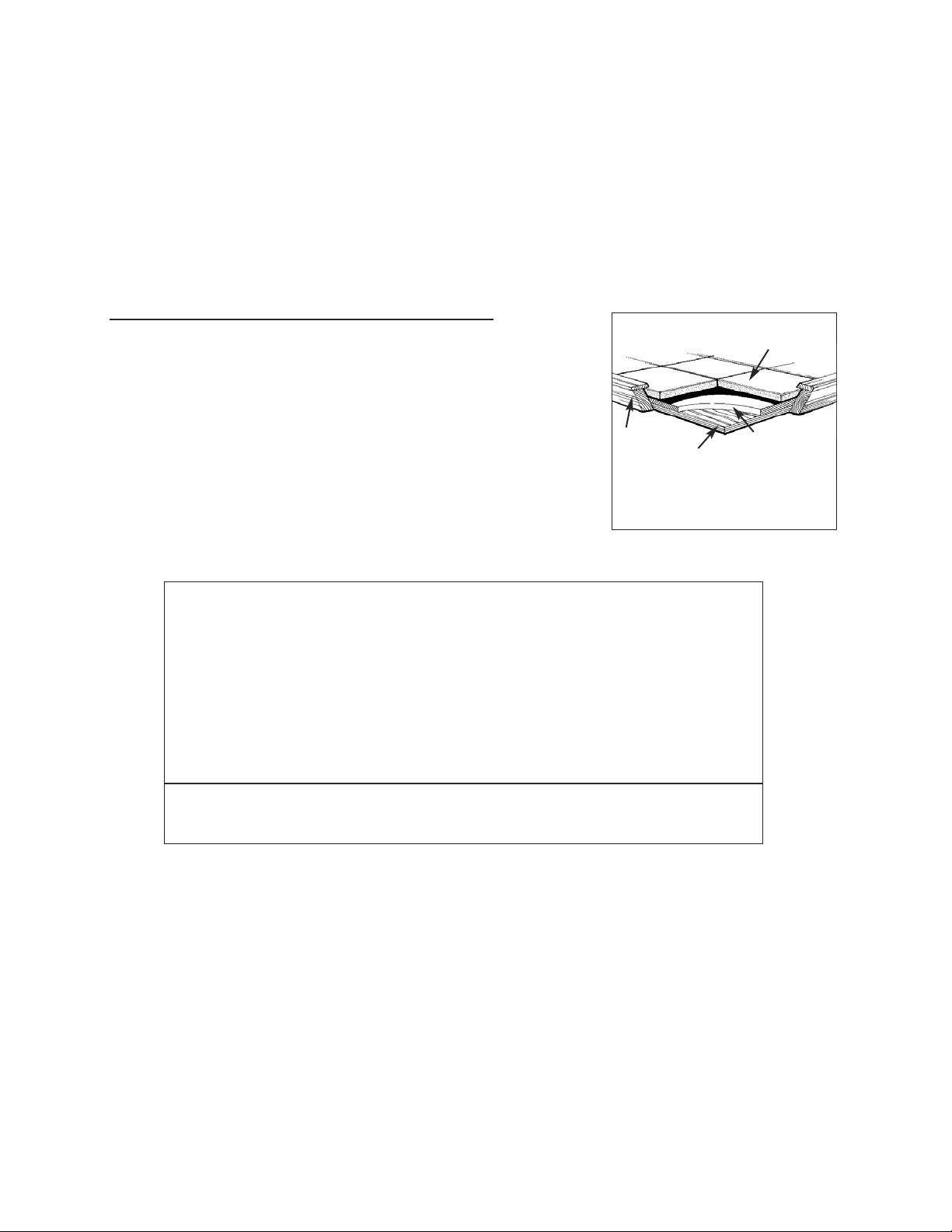
IF YOU CHOOSE TO BUILD YOUR OWN HEARTH PAD
1) Start with a plywood base or sub-floor.
Over this apply:
2) a layer of insulating board with an R-Value of at least 0.80 (R value
can be reduced by using the optional 3.5” ash lip)*. Depending on
the material you choose, the insulating board can be as little as 1/2”
thick. For additional help with material specifications, contact
Woodstock Soapstone Company at 1-800-866-4344 or at info@wood-
stove.com.
Over this apply:
3) 1/4” or greater of a decorative, non-combustible material such as tile,
slate, stone,
or brick. Use mortar or grout to set the material in place, then grout the seams.
*The R Value of the hearth pad can be reduced down to 0.40 with the use of the Progress Hybrid Ash
Lip EXCEPT WHEN USING THE SHORT LEGS.
Specifications for floor protectors may be listed in terms of R-value, K-value, or C-value. To convert K or
C value to R-value use the following formulas.
K to R: R=1/K x T (Thickness of the alternate material)
C to R: R=1/C
Once alternate materials have been converted to R-values, the values of multiple layers can be added to
determine the combined protection. If the overall R-value meets or exceeds the specified .80 (or .40) then
the materials are acceptable.
7
You can build your own hearth pad to fit
your decor. The hearth pad must meet a
trim
board
1/4” slate or tile
3/4” plywood
or subfloor
non-combustible
insulation board
R-values of common hearth materials:
Ceramic Tile 1/4” 0.020
Granite 1/4” 0.020
Slate 1/4” 0.025
Cement Mortar 1/2” 0.025
Cementboard 1/4”-1/2” 0.20-0.39
Common Brick 2.25” 0.450
Common Brick 4.00” 0.800
Please Note: Always check with the manufacturer of the hearth material used to
verify the R or K value.
K Values cannot be added, convert to R value before adding multiple layers.

DO NOT USE: Old-fashioned stove boards that were commonly sold in hardware stores as they DO
NOT have adequate protection and ARE NOT approved for primary floor protection under your stove.
Hearth Rugs also ARE NOT meant to be used as primary hearth protection. These are made to be used
in addition to an approved hearth, and are used as auxiliary decorative protection. They are not made to
be a substitute for an approved hearth pad.
Hearth Sizing:
Clearances for your 209 Progress Hybrid stove on the front, back and sides must be taken into considera-
tion when determining the placement and size of your floor protection. Vertical dimensions can be added
to horizontal dimensions on all but the loading door side to equal the clearances needed to a combustible
floor surface. For example, if you are required to have 12 inches in front of the stove for clearance and you
have a raised hearth that measures 6 inches high, the stove can sit 6 inches from the edge to equal the 12
inches required. The floor protection must extend under any horizontal connector pipe and 2 inches be-
yond each side.
STOVE WITH 10” LEGS
A. Floor protection in front of stove = 12” -OR- With optional ash lip= 8”
B. Floor protection at loading door side = 16”
C. Floor protection non-loading door side = 8”
D. Floor protection behind stove (top vent or rear vent) = 6”
Minimum hearth size in a parallel installation is
43”D x 54.5”W. (10” Legs & NO Ash Lip) -or- 39”D x 54.5”W (10” Legs with Front Ash Lip)
47” D x 54.5” W (Short Legs)
Recommended size is 48” D x 60”W or larger (10” legs or short legs with ash lip)
STOVE WITH SHORT LEG OPTION (Requires ash lip)
A. Floor protection in front of stove = 16”
B. Floor protection at loading door side= 16”
C. Floor protection at non-loading door side = 8”
D. Floor protection behind the stove = 6”
8
B
C
D
A
PARALLEL HEARTH PAD
Optional Ash Lip
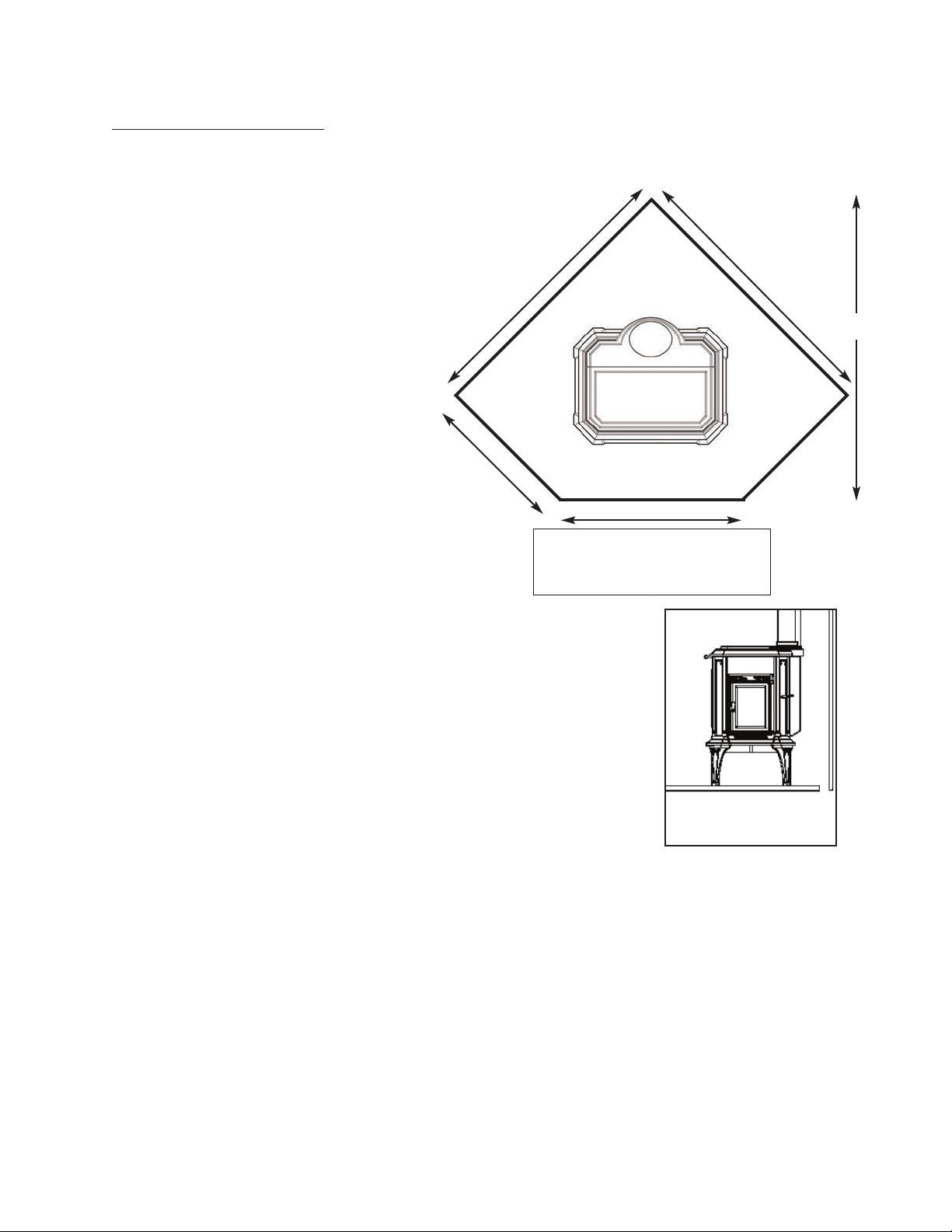
CORNER HEARTH PAD
Minimum hearth size in a corner installation must be 54”x54” (with the front corner cut off). NOTE: On a
hearth of minimum size, the stove will not be centered left to right, but will meet the minimum required
clearances.
Calculating a Corner Hearth Pad (per NFPA 211):
A=C x 1.414 + W/2 + D + Front Hearth Requirement
A =distance from corner to the front of the hearth pad
C = clearance from rear corner of appliance to wall (12” w/
rear heat shield)
1.414 = a constant
W/2 = one half the width (15.25”)
D = appliance depth (25”)
Front Hearth Clearance= 12”
Example:
Progress with the Rear Heat Shield & Pipe Shield
A= 12” x 1.414 + 15.25 + 25”+12” A= 69”
Note: If using the optional Ash Lip A= 65”
If using the optional Short legs and Ash Lip A= 73”
WALL PROTECTION
The Model 209 Progress Hybrid stove has been tested to UL standards for
clearances to combustible walls. The minimum clearances to unprotected walls
are as follows:
Minimum clearances with no heat shields to unprotected combustible walls:
From the back-------------------36”
From the sides-------------------24”
Do not assume that a wall is not combustible because it has a nonflammable
surface. A wall with any combustible materials in it must be considered com-
bustible. For example, a brick wall attached to wood studs is considered a com-
bustible wall. Over time, heat will pass through bricks and heat the wood, lowering the ignition
temperature of the studs, possibly resulting in a fire. As waves of radiant heat energy meet a combustible
object, heat is absorbed and the temperature of the object is raised, which can result in spontaneous com-
bustion. Similarly, wood-framed walls which are covered with tile, stone or fire-rated sheetrock must be
considered combustible. Fire-rated sheetrock is also considered combustible due to the paper covering.
If you wish to install your stove closer to a combustible wall than standard clearances will permit, you
can either attach a UL approved stove & pipe shield, or mount a protective non-combustible shield on the
wall.
Stove and Pipe Shields:
Clearances can be reduced by attaching a UL approved heat shield and pipe shield. Woodstock Soap-
stone Company carries heat shields specifically designed for this stove. When using one or both of these
shields, clearance is measured from the back of the shield to the combustible wall. The clearance be-
hind the stove can be reduced to 7 inches. The clearance behind the pipe can be reduced to 6 inches.
9
A=69”
60”
60”
43”
23”
CORNER HEARTH PAD
Progress Hybrid shown above
centered left to right
Rear heat shield & pipe
shield greatly reduce re-
quired clearances
Wall shields:
Clearances can also be reduced by mounting a ventilated shield on the wall that extends 36” out beyond the
stove (see diagram below). If you are installing wall protection, it should be spaced out from the wall one
inch. This air space allows air to flow freely behind the shield, cooling the combustible wall and preventing a
pocket of hot air from being trapped behind the shield. The wall protection can be attached to the studs using
long screws and ceramic wall spacers. The spacers should not be installed directly behind the stove. The top
and either a.) both sides, or b.) the bottom must be left open for adequate ventilation.
*These clearances meet or exceed requirements of NFPA 211, Standard for Chimneys, Fireplaces, Vents, and Solid
Fuel Burning Appliances.
• These clearances apply to walls, ceilings, furniture and other combustibles.
• The 36” Vertical Stack Shield attaches to the back of the stove pipe and prevents excess heat from being
radiated from the pipe. Heat shield protection is only required for the first 36” of vertical connector pipe.
• At least 30” is required from the front of the stove to combustibles (such as curtains, wall hangings, and
furniture).
The same clearances from your stove and stove pipe apply to both fireplace and freestanding installations. Be
particularly careful to check clearances to a wood mantel or a wood fireplace facade. You must maintain a 30”
clearance to an unprotected wood mantel. See Fireplace Installations on Pages 5-6.
10
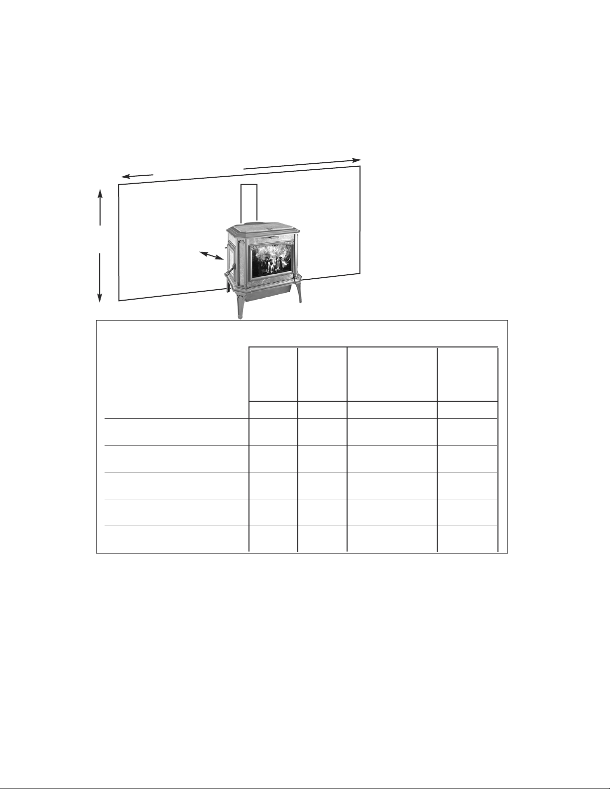
98.5” Required Width
67.5”
Required
Height
12”
EXAMPLE:
Wall shield sizing with the 12” Mini-
mum Clearance to Combustible
Wall/Top Venting.
Note: Wall shield size will vary de-
pending on distance between stove
and wall.
Clearance Table For Model 209 PROGRESS Hybrid
Type of Installation Top Vent Rear Vent Rear Vent with elbow Stove Sides
Stoveck Pipe goes
Type of protection
Stove Back Stovepipe
No Protection 36” 36” 36” 18” 24”
3
1
/2” thick Masonry Against 24” 24” 24” 12” 16”
Combustible Wall*
3
1
/2” thick Masonry with 12” 12” 18” 9” 12”
1” ventilated airspace*
24 ga. sheet metal with 12” 12” 18” 9” 12”
1” ventilated airspace*
1/2” thick non-combustible 12” 12” 18” 9” 12”
insulation board with 1” airspace*
UL Listed Rear Heat Shield and 6” pipe 7”stove 16” 6” 24”
36” Vertical Stack Shield 7” stove
Clearance
from stove
back and pipe,
which goes
straight up
Clearance
from stove
back and pipe,
which goes
straight back
Clearance from stove back
and vertical single wall
connector pipe
11
A
B
E
C
WITH REAR HEAT SHIELD & PIPE SHIELD ATTACHED
A. Back of stove shield to wall = 7” D. Side of stove to wall = 24”
B. Back of pipe shield to wall = 6” E. Side of pipe to wall = 36”
C. Above pipe to ceiling = 18”
D
NO HEAT SHIELD
A. Back of stove to wall = 36” D. Side of stove to wall = 24”
B. Back of pipe to wall = 18” E. Side of pipe to wall = 36”
C. Above pipe to ceiling = 18”
CLEARANCE INSTALLATION DIAGRAMS
1) Parallel Installation, Single Wall Pipe, Top Vent
A
B
D
E
2) Parallel Installation, Single Wall Pipe, Back Vent
NO HEAT SHIELD
A. Back of stove to wall = 36” D. Side of stove to wall = 24”
B. Back of pipe to wall = 18” E. Side of pipe to wall = 36”
C. Above pipe to ceiling = 18”
WITH REAR SHIELD & PIPE SHIELD ATTACHED
A. Back of stove shield to wall = 16” D. Side of stove to wall = 24”
B. Back of pipe shield to wall = 6” E. Side of pipe to wall = 36”
C. Above pipe to ceiling = 18
C
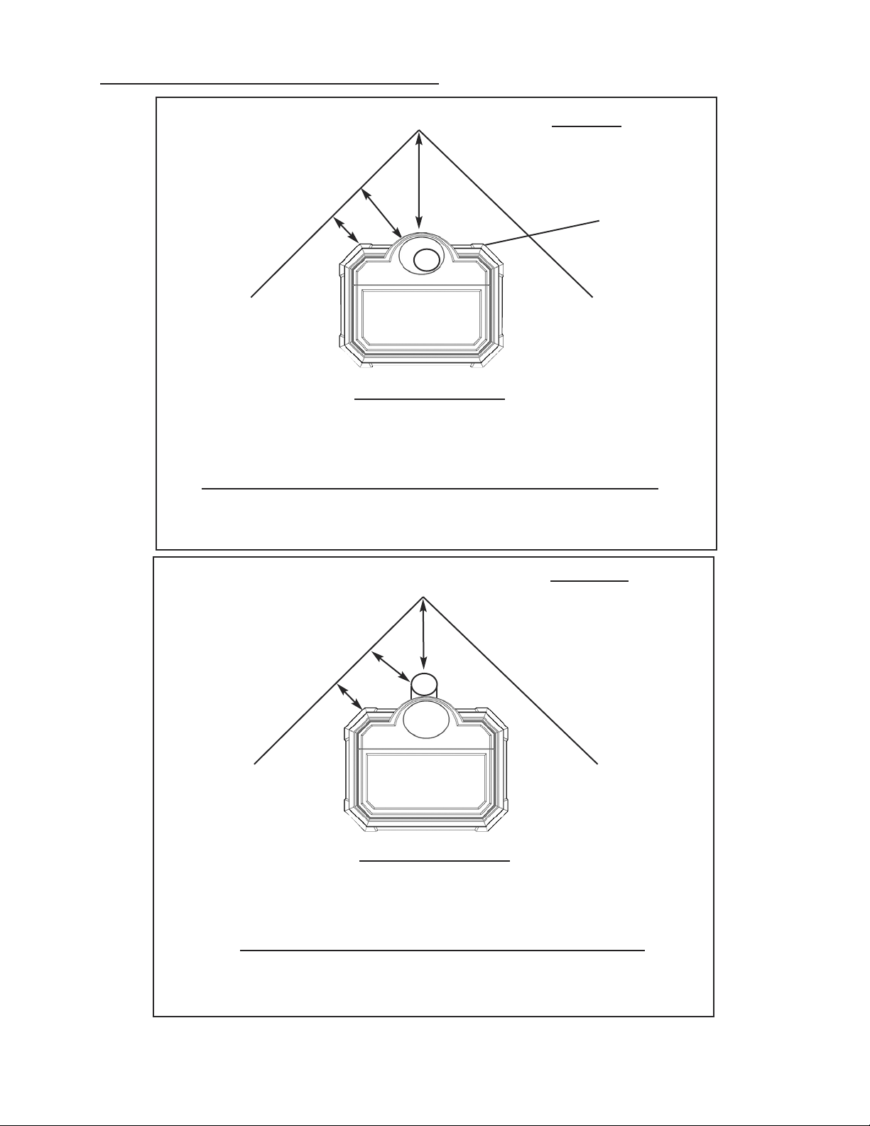
A
B
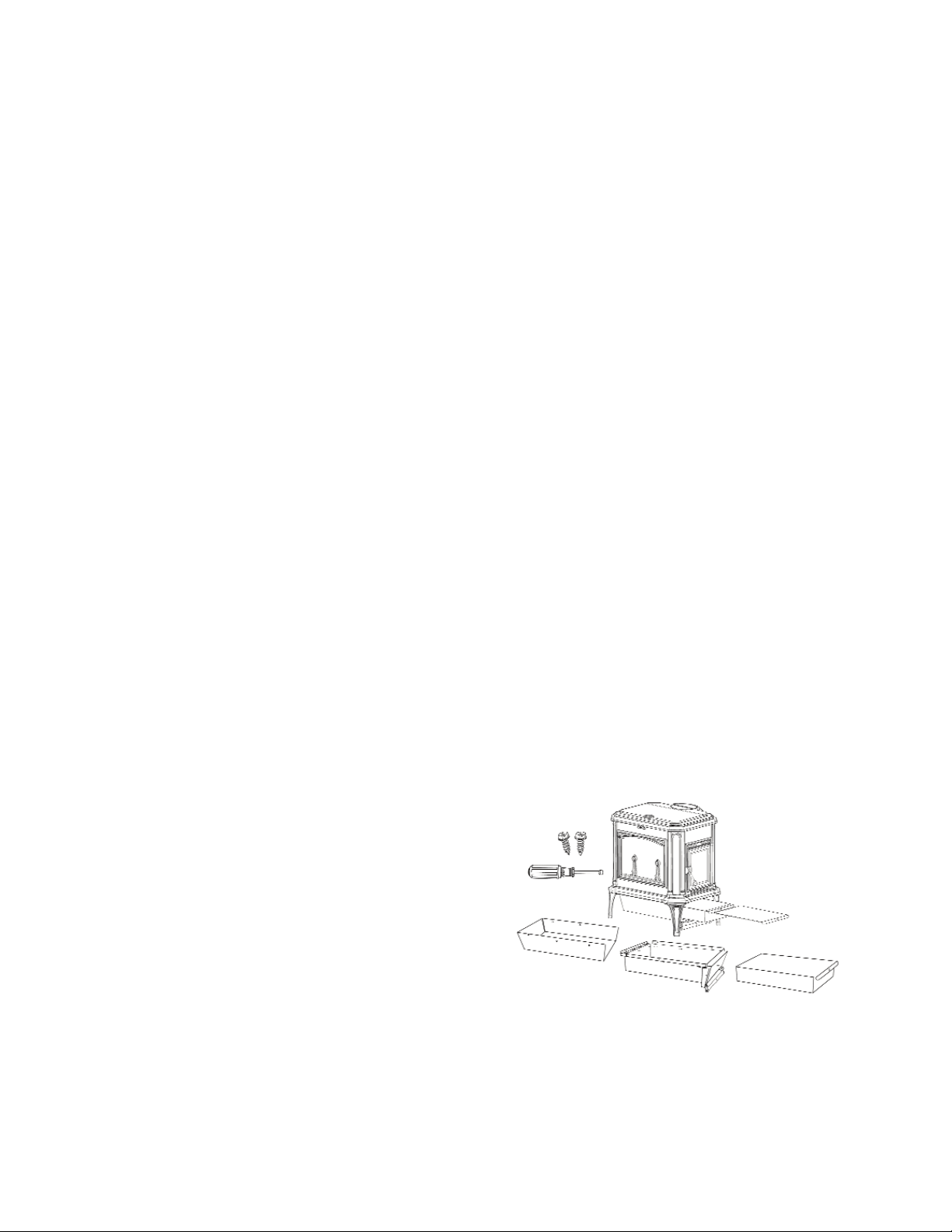
A
NO HEAT SHIELD
A. Stove corners to side walls = 36” (determines placement)
B. Pipe to side walls = 18”
C. Pipe to corner =18”
WITH REAR SHIELD & PIPE SHIELD ATTACHED
A. Stove corners to side walls = 12” (determines placement)
B. Back of pipe shield to side walls = 6”
C. Pipe to corner =6”
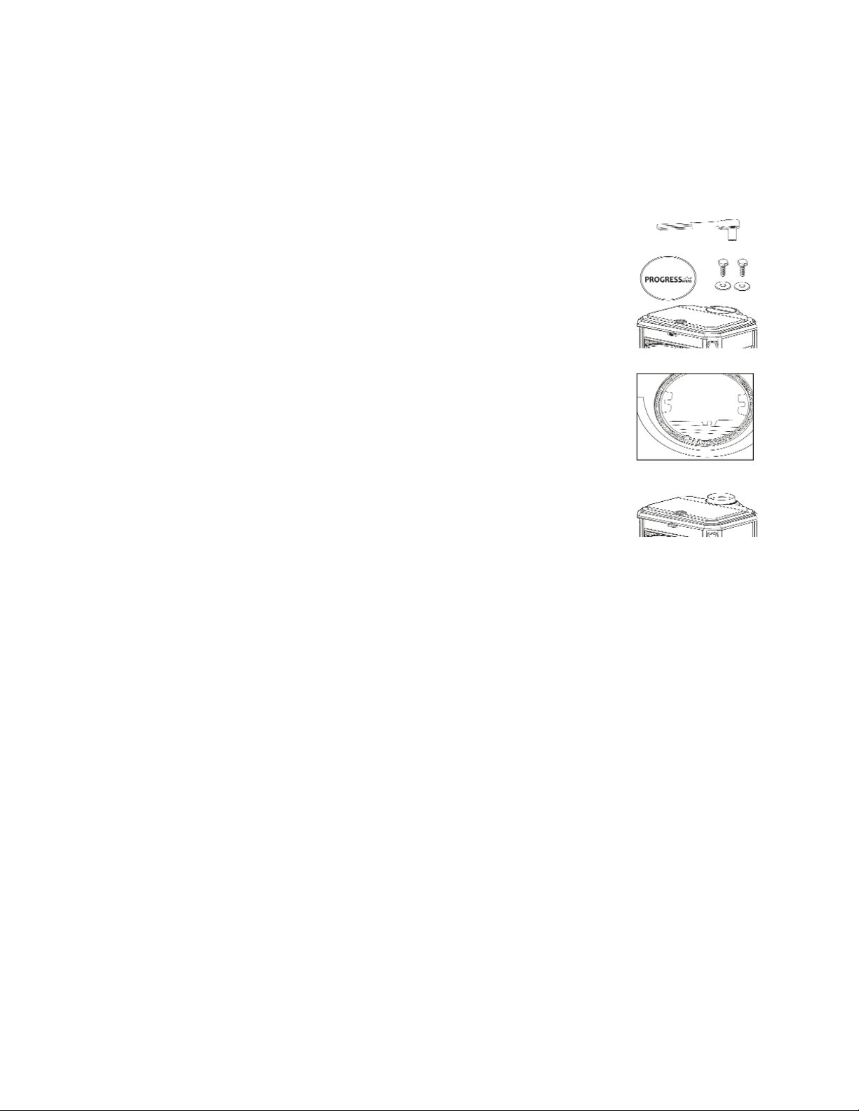
B
4) Corner Installation, Single Wall Pipe, Back Vent
C
C
TOP VENT
NO HEAT SHIELD
A. Stove corners to side walls = 36” (determines placement)
B. Pipe to side walls =18”
C. Pipe to corner =18”
WITH REAR HEAT SHIELD & PIPE SHIELD ATTACHED
A. Stove corners to side walls = 12” (determines placement)
B. Pipe to side walls = 18”
C. Pipe to corner =12”
3) Corner Installation, Single Wall Pipe, Top Vent
CLEARANCE INSTALLATION DIAGRAMS
12
SETTING UP YOUR STOVE
Your Model 209 Progress Hybrid Wood stove has been shipped fully assembled except for five parts:
1) The stove legs 2) A.The bottom heat shield (if no ash pan) or B. Optional ash pan 3) The flue
collar/cover plate 4) Loading door handle.
(1) How to install the legs:
1) The Progress legs are packed inside of the stove along with step by step instructions and mounting
hardware. Remove them from the packaging and read through the instructions. The legs must be
installed on your stove prior to use.
2).Remove the outer pallet extensions to access the the pre-drilled mounting holes in the stove base.
3) Hold the leg in position and start the bolt and washer by hand. Tighten with a 9/16” socket or
wrench.
4) Repeat step three for all of the legs. Confirm that all of the legs are firmly tightened.
5) Follow the instructions for removing the stove from the pallet once the legs are installed.
Note: Use the same procedure to install the optional short legs if needed.
(2a.) How to attach the Progress fill plate, retainer plate, and bottom heat
shield (no ash pan model):
The bottom heat shield prevents excess heat from being radiated from the stove onto the hearth.
Illustrated instructions and hardware will be packed with your bottom heat shield. (Refer to the diagram
on page 34)
1. Install the firebox fill plate. The top side has several rows of wavy lines. Be sure it lies flat and is
evenly spaced front to back and side to side. It is held in place by the retainer plate.
2. Hold the retainer plate up to the base of the stove. There are twelve holes in the retainer plate that
align with six holes in the base casting and six holes in the fill plate. Align the holes and secure the
retainer plate to the base and fill plate.
3. Secure the bottom heat shield to the base with the bolts provided. An attachment illustration is
provided with the heat shield.
(2b.) How to attach the Progress ash pan:
1. Illustrated instructions and hardware will be packed
in your ash pan. Read through them before you
begin. (Refer to the diagram on page 35) Install the
ash grate. Be sure it lies flat and is evenly spaced
front to back and side to side.
2. Next install the ash pan holder. The mounting holes
are located on the outer perimeter of the gasket
channel under the stove. Be sure your ash pan door
is at the same end of the stove as the loading door,
line up the holes in the ash pan holder to the
corresponding holes on the base of the stove. Tighten
the bolts gradually and evenly.
MAKE SURE THE HOLDER IS COMPLETELY SEATED IN THE GASKET TO PREVENT AIR
LEAKS!
3. Attach the ash pan heat shield and shield extensions to the ash pan holder. The open end of the heat
shield accomodates the ash pan door. Line up the holes in the heat shield with the holes in the shield
extensions and the holes in the rails of the ash pan holder. Secure with provided sheet metal screws.
13
4. Open ash pan door and slide the ash pan into the holder. REMOVE THE ASH PAN COVER
BEFORE LIGHTING YOUR STOVE.
(3) How to attach the Progress flue collar & cover plate:
Your Progress Hybrid will arrive with the flue collar pre-installed on the rear exit and the cover plate
on top of the stove. The flue collar and cover plate are interchangeable. If you prefer to top vent your
stove, please follow the steps below.
Top Venting:
1. First, reach in through the back flue collar and remove the 2 bolts and washers
that secure the cover plate to the stove. With the top cover plate removed, reach in
and remove the 2 bolts and washers that secure the flue collar to the back of the
stove.
2. Next, install the cover plate on the back exit of the stove. Hold the cover plate
over the flue exit that will not be used. Line up the holes of the cover plate with the
tabs located to the right and left of the flue exit. Place a flat washer over one of the
bolts provided and thread it into the hole in the cover plate. Thread the second bolt
and washer through the other tab into the cover plate. Tighten the bolts.
3. Place the flue collar over the top flue exit. Be sure it is seated in the gasket.
4. Line up the holes in the flue collar with the tabs to the right and left of the flue
exit. Secure flue collar with the remaining bolts and washers. Tighten the bolts.
5. Do not overtighten these bolts: simply tighten until each is firmly seated in the
gasket and the bolts are snug.
(4) How to install the load door handle:
1) The door handle assembly consists of a threaded ring and a spacer. Detailed instructions are packed
with the parts.
2) Thread the rod into the door latch.
3) Slide and hold the spacer over the rod.
4) Turn the ring onto the threaded hole already attached to the loading door. The ring should be tight
in the vertical position.
14
OPERATION
Seasoning Your Stove
Both soapstone and cast iron need to be seasoned. The seasoning can be accomplished through a series
of small to moderate fires. Your Woodstock Soapstone Stove is an easy stove to season, because even a
small fire will provide hours of radiant heat once the stove is warm. There are two things you will
notice during the first fire:
First, there will be a hot, acrid smell as the stove heats up. This smell is a result of the paint on the
cast iron curing. You will want to have your first fire on a day when you can open the windows in the
house to provide adequate ventilation. The odor is non-toxic and will only be present for the first few
fires.
Second, there will be some condensation on the glass. This condensation is a result of moisture being
driven out of the furnace cement in the stove and condensing on the inner surface of the glass. It takes a
couple of small fires to season the stove and remove this excess moisture.
After the first few fires, the texture and grain of the stone may become slightly more pronounced, and
the color may deepen a shade.
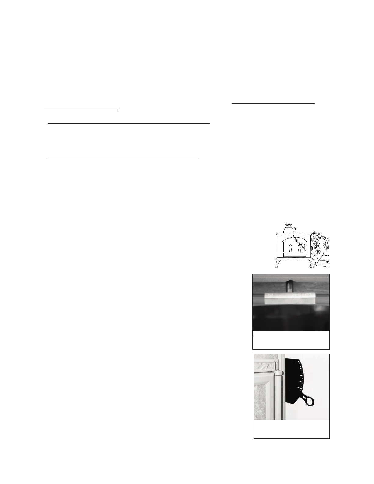
Starting a Fire And Establishing Proper Draft
1. Open the catalytic bypass. Turn the bypass handle clockwise to open the bypass door. It will stop
when the bypass is fully open. (Fig. 1)
2. Open the combustion air damper by lowering the damper lever all the way
down to the full open position. With the lever in the down position, maximum air
is allowed into the firebox. (Fig. 2)
3. Always confirm there is adequate draft before lighting the fire. Hold a lit
match or light a small piece of newspaper in the top of the firebox, where smoke
exits. If the flame is drawn out of the firebox, toward the flue, proceed with
lighting the fire. If the flame stands still or is pushed away from the flue
exit, you must establish a good draft before lighting a fire. A hair dryer or
heat gun pointed at the flue exit is a good way to establish draft without
creating a lot of smoke. After you think you have draft, re-test with a match.
4. Once good draft has been established, build a fire on the floor of the
firebox. Do not use additional grates, andirons or any other methods to
support the fuel in the firebox. Start with crumpled newspaper and dry
kindling.
5. Add small splits of firewood once the kindling has ignited. This will
establish a bed of hot coals.
6. Add small to medium splits onto the hot coals. Assuming the wood is
dry, the fire should spread through the wood. After about 10 minutes, close
the air damper about half way between fully open (all the way down) and
fully closed (all the way up).
7. After the stove top temperature reaches 250°F or your single wall pipe
temperature reaches 300-350°F, close the bypass by turning the handle
counter clockwise into the closed position. It will stop when the bypass is
fully closed. All of the smoke from the firebox will now pass through the
catalytic combustor. The combustor will generate a substantial amount of
heat as it “burns” the smoke passing through it.
15
The amount of combustion air
available in the firebox is controlled
by the damper lever. (Fig 2)
Use your bypass handle to engage or
disengage your catalytic combustor.
(Fig 1)
8. Adjust the air control damper to a lower setting by lifting the lever up.
The lower the burn rate, as less air is entering the firebox. The final
damper setting will be determined by the desired heat output from the
stove, the condition of the wood being burned, and the draft through the
chimney system.
Engaging the Catalytic Combustor
The catalytic combustor will start to burn the gases and particles in the
smoke when the temperature of the smoke reaches approximately 500ºF,
or after about 10-15 minutes of establishing a strong fire. Each stove
comes with a surface thermometer and a probe thermometer. Use the
surface thermometer to monitor stove surface temperatures. The temperature on top of the stove is
approximately 1/2 the temperature inside the stove, so when the thermometer on the stove top reads
250ºF, it is 500ºF inside. You will find that after the combustor is engaged, surface temperatures will
often rise considerably- evidence that the combustor is producing lots of heat! The probe thermometer
reads the temperature just one inch downstream from the exit face of the catalyst.
Engage the combustor by turning the bypass handle (front of the stove) counter clockwise until it clicks
into its position. Then reduce the air damper to achieve the desired burn rate. Make fine adjustments
to your air control damper by moving it slightly up or down. You may find that you can achieve the
longest burn when the damper is only slightly open. In the Progress Hybrid, allowance is made for a
small amount of primary and secondary air to enter the stove even when the damper is fully closed, and
the stainless steel catalyst will work efficiently at low to moderate firing rates, thus preventing creosote
formation or excessive smoke from your chimney.
Low & Overnight Burning
These instructions are intended as a guide to operating your wood stove. Your timing and final damper
settings will vary depending on chimney draft, type of wood, moisture content of the wood and size of
the splits. The Progress Hybrid is simply designed and intended to be user friendly, but it will take some
practice to get used to it.
1. Before you open the loading door, you must fully open the catalytic bypass and the air damper. Wait
a minute or so for a strong draft to be established to prevent smoke from spilling back into the room.
2. Stir up the hot coals. If necessary, excess ash should be removed before reloading the firebox. If your
stove has the optional ash pan, simply rake the hot coals back and forth in the firebox to allow the loose
ash to fall through the grate into the ash pan. If your stove does not have an ash pan, push the hot coals
to one side and shovel the loose ash into a non-combustible ash container with a tight fitting lid. Dispose
of the ash properly.
Never put an ash container on a combustible surface, like a wood floor.
3. Place several small splits on top of the hot coals and allow them to ignite.
4. Load the firebox to capacity leaving space for secondary combustion, with a mix of larger and
smaller splits. Close the loading door.
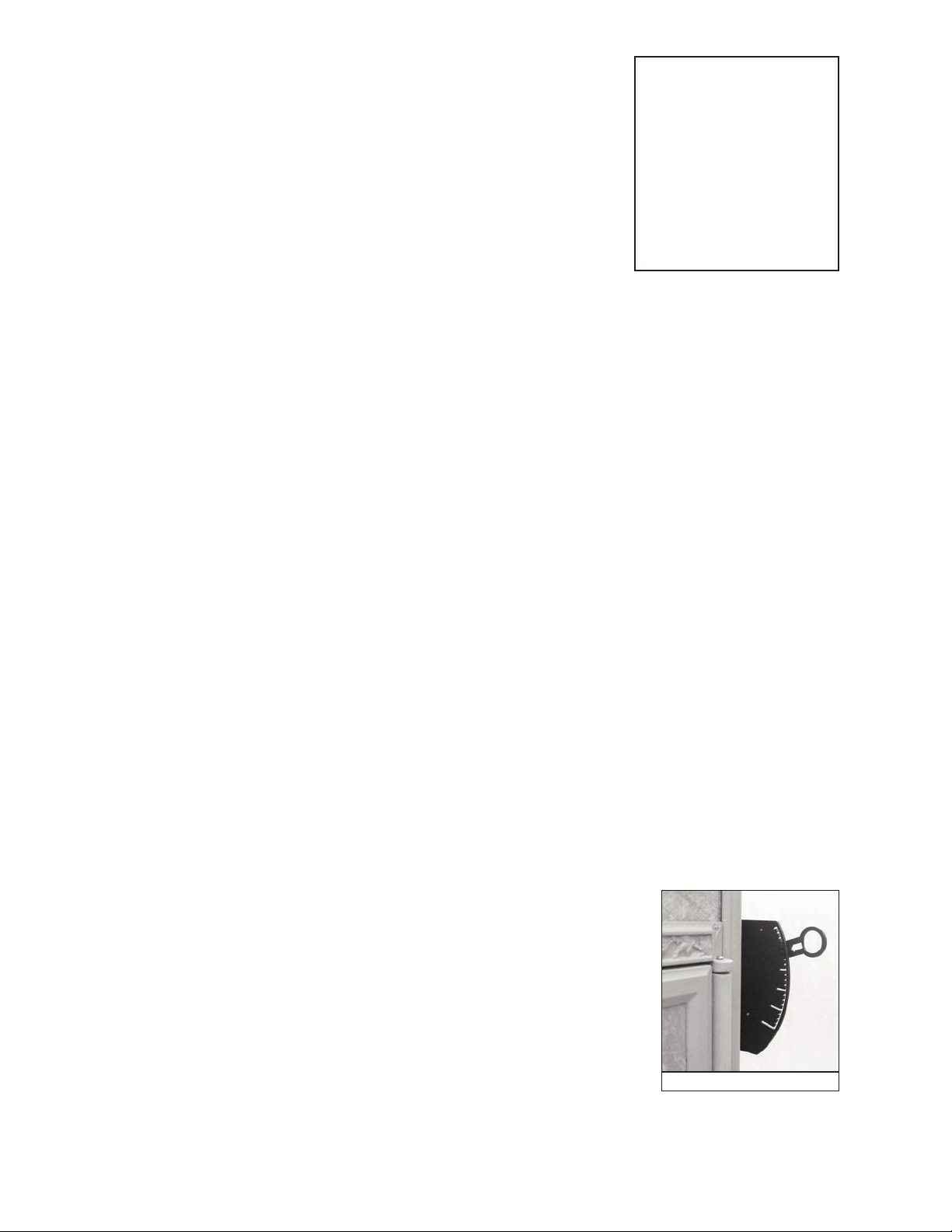
5. Adjust the air damper to its the low burn setting by raising the lever up to
reduce the air flow, generally around the last big notch.(fig 3).
6. Close the catalytic bypass, by turning the handle counter-clockwise until it
stops.
7. Initially the fire may appear to die out. This may cause a small amount of
soot to collect on the glass. Any buildup on the glass should go away with
higher t emperature burns.
Never burn the stove with the air damper fully open except when kindling a fire or reloading the
firebox.
16
CAUTION
NEVER USE GASOLINE,
GASOLINE TYPE LANTERN
FUEL, KEROSENE, CHAR-
COAL LIGHTER FLUID OR
SIMILAR LIQUIDS TO
START OR “FRESHEN UP” A
FIRE IN THIS STOVE. KEEP
ALL SUCH LIQUIDS WELL
AWAY FROM THE STOVE
WHILE IT IS IN USE.
Lower Air Damper Setting (fig 3)

Never build a roaring fire in a cold stove. It takes at least 30 minutes to heat the soapstone panels of
the Progress.
Attempts to reach high temperatures very quickly could result in damage to the cast iron or
soapstone parts.
Burning for Higher Heat Output
These instructions are intended as a guide to operating your wood stove. Your timing and final damper
settings will vary. The Progress Hybrid is simply designed and intended to be user friendly, but it will
take some practice to get used to it.
1. Before you open the loading door, you must fully open the catalytic bypass and the air damper. Wait
a minute or so to establish a strong draft. This will help to keep smoke from spilling into the room.
2. Stir up the coals and remove excess ash as needed.
3. Place several small splits on top of the hot coals and allow them to ignite.
4. Load the firebox to capacity leaving space for secondary combustion, with a mix of larger and
smaller splits. Close the loading door.
5. Allow the fresh wood to become involved in the fire. With dry wood this may take 5-10 minutes. Lift
the air damper up to the close approximately half way.
6. Close the catalytic bypass by turning the bypass handle counterclockwise until it stops.
7. You should see the flames from secondary combustion at the top rear of the firebox becoming more
active. Adjust the air damper to approximately one quarter open.
Ash Removal
NEVER BURN THE STOVE WITH THE ASH DOOR OPEN!
Without an ash pan:
If your Progress Hybrid does not have an ash pan you will have to remove ash through the side door,
approximately every 5-7 days if the stove is in continuous operation. You do not have to let the fire die
out completely to remove the ashes, but the fire must be reduced to hot coals. First make sure that both
the catalytic bypass damper and the air control damper are open. This will increase the draft and
prevent smoke from entering the room.
Open the side door and move the hot coals to one side of the firebox. Scoop out the ashes that were
underneath the coals, and then reverse the procedure. Leave some ash and hot coals in the bottom of the
stove to help rekindle a fire.
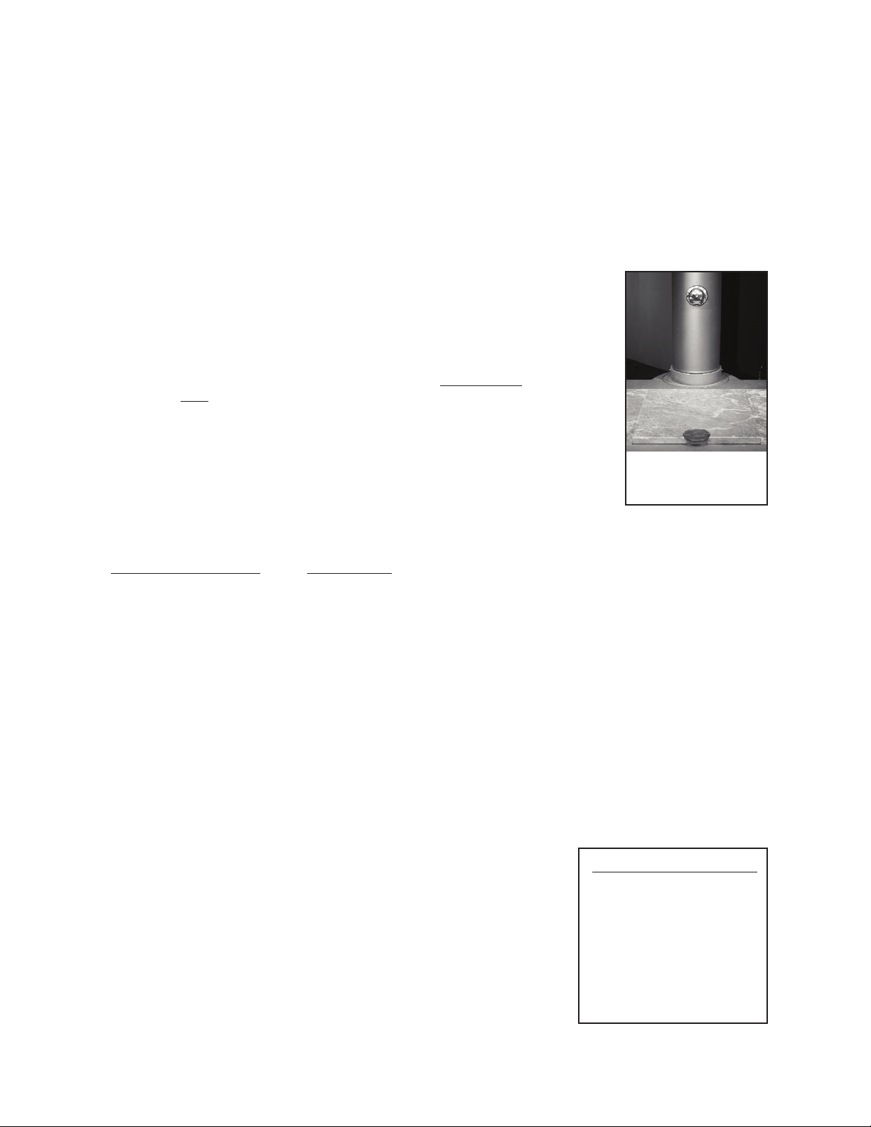
With an ash pan:
If your Progress Hybrid is in continuous operation, you will probably need to empty the ash pan every
7-10 days. You do not have to let the fire die out completely, but make sure that it is reduced to hot
coals. Open the catalytic bypass damper, and open the air control damper. Remember to wear stove
gloves - the ash pan will be hot! Open the ash pan door located below the loading door. Carefully slide
the lid into place on the top of the ash pan and remove the ash pan from the base of the stove. The lid
slides over the long top edges of the ash pan. Close the ash pan door before emptying the ashes into an
appropriate container.
Do not open the ash removal door while the stove is in the middle of a long burn, because the
additional draft created under the fire could cause the stove to burn excessively hot and the ash pan
itself will be very hot, and full of live coals. If you are burning your stove 24 hours/day, it is often
easiest to empty the ashes first thing in the morning, after an overnight burn.
Ashes should be emptied into a metal container with a tight-fitting lid. The closed container of ashes
should be placed on a noncombustible floor or on the ground, well away from all combustible materials,
pending final disposal. If the ashes are disposed of by burial in soil or otherwise locally dispersed, they
should be retained in the closed container until all cinders have thoroughly cooled. Live cinders can
17
take up to 36 hours to cool. Woodstock Soapstone Company offers a black metal ash holder with a
hinged lid that closes tightly. Four sturdy legs keep it off the floor, and the wooden handle is not only
decorative, it will also protect your hands.
Never shovel ashes into a combustible container like a cardboard box or a plastic bucket. Do not use
a vacuum cleaner to remove ashes unless it is specifically designed for woodstove ash removal. Do
not ever leave a container of hot ashes on a wood floor or porch.
The Surface Thermometer and Probe Thermometer
We recommend placing the thermometer 8”-10”above the flue collar on single wall stove pipe if the
stove is vented out the top. If the stove is rear vented, the surface thermometer should be placed on the
cast iron cover plate toward the back of the stove. If you are reading the single
wall stove pipe temperature, the interior flue exhaust temperature is about twice
as hot. Since the 22 gauge sheet metal pipe is more reactive (faster heat transfer)
than the stove top, you will find you can engage the combustor sooner. We
recommend engaging your catalytic combustor once the pipe thermometer
reaches 300°-350° F. Stove top temperatures should reach approximately 250°F.
Once the combustor is engaged, you should see the stove surface temperature
rise and the pipe temperature drop, indicating catalytic combustor activity. From
a cold start it may take 30-45 minutes to get to the stove up to temperature. If you
are reloading a hot stove, wait approximately 10-15 minutes before engaging the
combustor.
The thermometer is not a precise instrument – it will not tell you the exact
temperature inside the firebox or in the flue. If reading the surface temperature
the thermometer will not register changes in temperature quickly due to the
thickness and heat retention of soapstone. We supply the thermometer to give you some idea of what is
going on inside the stove, and to provide a guide for operation.
STOVE TOP READING OPERATION
over 300º. . . . . . . . . . . . . . . . . . . . . OK to engage the combustor
400-600º. . . . . . . . . . . . . . . . . . . . . . Normal operating temperature
600-700º. . . . . . . . . . . . . . . . . . . . . . High burn range
over 700º. . . . . . . . . . . . . . . . . . . . . DO NOT burn in this range
The probe thermometer can be inserted into the port beside the flue collar in the rear of the stove. The
probe thermometer wll measure the temperature immediately downstream of the catalytic combustor.
The sensing end of the probe extends to within 1 inch of the face of the catalyst. The probe is calibrated
from room temperature to 1700 degrees F. The catalyst can be engaged as soon as the temperature on
this probe exceeds 500 degrees F, or as soon as the temperature on the pipe thermometer exceeds 250
degrees (see above). The best operating range for the catalyst is from 500 - 1400 degrees F. When the
temperature on the probe thermometer exceeds 1400
o
F, we recommend closing the damper to prevent
excessive heat from occuring
Overfiring
The cast iron parts in your Woodstock Soapstone Stove are of the finest
quality. Our cast iron parts have been made in the same foundry since the
mid 1980’s, and the foundry itself has been in business for over one
hundred years. Each cast iron part is inspected by our stove builders
before it becomes part of a stove. However, cast iron is not indestructible.
Experts have shown that cast iron begins to oxidize (reddish or whitish
discoloration) at 1400º F. Burning a stove frequently at excessive
temperatures is known as overfiring. When the surface temperature is
consistently over 700º F, the stove has reached 1400º F inside. Operation
with temperatures in this range can lead to cast iron warping, becoming
brittle, and eventually deteriorating completely. It can shorten the useful
life of the catalytic combustor.
18
Place the surface thermometer
8” above the stove top for top
vent, or on the cover plate for
rear vent
DO NOT OVERFIRE!
ATTEMPTS TO ACHIEVE
HEAT OUTPUT RATES
THAT EXCEED STOVE
DESIGN SPECIFICATIONS
CAN RESULT IN PERMA-
NENT DAMAGE TO THE
STOVE AND TO THE
CATALYTIC COMBUSTOR.
Avoid overfiring by letting the combustor and secondaries do most of the work in the stove. Your stove
is operating at peak efficiency when the combustor is “engaged”and the secondaries are ignited, with the
damper lever set to a low to moderate setting, and the logs are glowing with secondary flames apparent.
You will get the greatest amount of heat per pound of wood when the stove is operated in this manner.
Daily Use
Your Progress stove is well-suited for continuous firing on a 24 hour-a-day basis. It will burn for hours
on one load of wood, and will provide steady, even heat for hours after the fire dies down. One of the
qualities of soapstone most enjoyed by wood burners is its ability to absorb heat and then to release the
heat evenly. When the temperature on top of the stove drops below 250ºF during an all-night burn, it is
not necessary to disengage the combustor. You need only disengage the catalytic combustor when you
kindle a fire, or reload the stove. Once the catalyst is ignited, it will continue to function as long as there
is smoke to burn. This is true even if the surface temperature on top of the stove drops below 250ºF at
the end of a long burn.
Your connector pipe and chimney or chimney pipe should be inspected at regular intervals (not less
than once every two months). Examine the connector pipe for creosote, corrosion, loose seams, or exces-
sive soot. Clean and replace as necessary. The chimney or chimney pipe should be cleaned and checked
by a certified specialist once a year. A small mirror held at the cleanout door of a masonry chimney will
be helpful. For a class A prefabricated metal pipe, some disassembly is usually required.
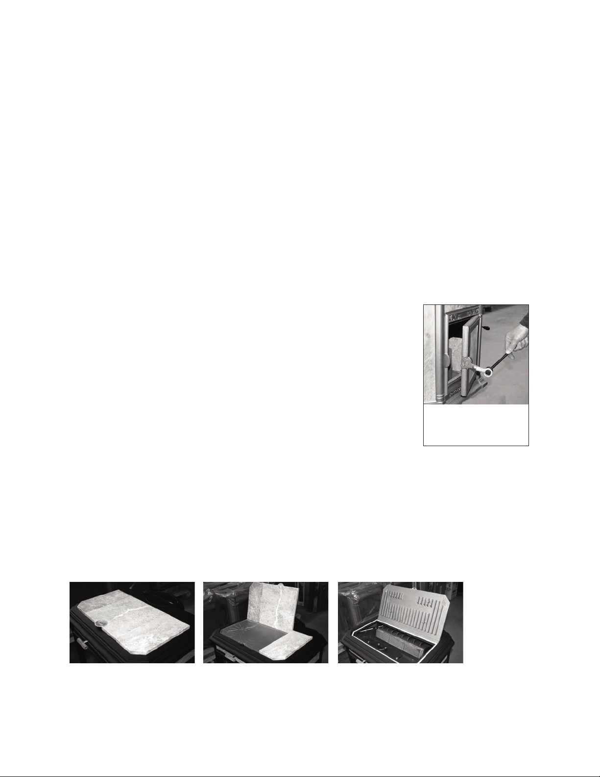
The Fall-Away Handle
The “fall-away” handle, which comes with your stove, can be used to operate
the side door latch or the catalytic bypass damper. Simply insert the round
knob end of the Fall-Away Handle into the door pull ring to open/close, or
latch/unlatch the loading door. The loading door and the pull ring and the
catalytic bypass handle are very hot, so use the tool provided. The “fall-away”
handle conforms to UL requirements and is made so that if you let go of it, it
will “fall-away” from the stove and not become too hot to handle.
The Progress Cook Top
The top lid of the Progress wood stove consists of a three-piece stone set and
a cast iron plate below. The lid has been designed to enhance the beauty and versatility of your stove.
The soapstone serves to provide long lasting radiant heat as well as the perfect cooking surface for foods
to simmer over moderate heat for longer periods. The stone panels can be raised individually or
collectively to expose the cast iron cook top underneath. The cook top has three distinct areas that
provide high, medium, and low temperature zones for more cooking flexibility. The center “burner” is
flush and delivers the highest heat. The left is elevated about 1/16” and provides medium heat. The right
is raised 1/8” and has the lowest temperature. In general, if the temperature on the stone is 300°-350° the
center of the cast iron cook top is 500°-550°. The temperature drops approximately 50° per 1/16” of
height, so the left burner would be 50° cooler than the center and the right burner 100° cooler. The cast
iron cook top is not designed as a cooking surface and food should always be placed in a heavy duty
Dutch oven or skillet, not directly onto the cast iron.
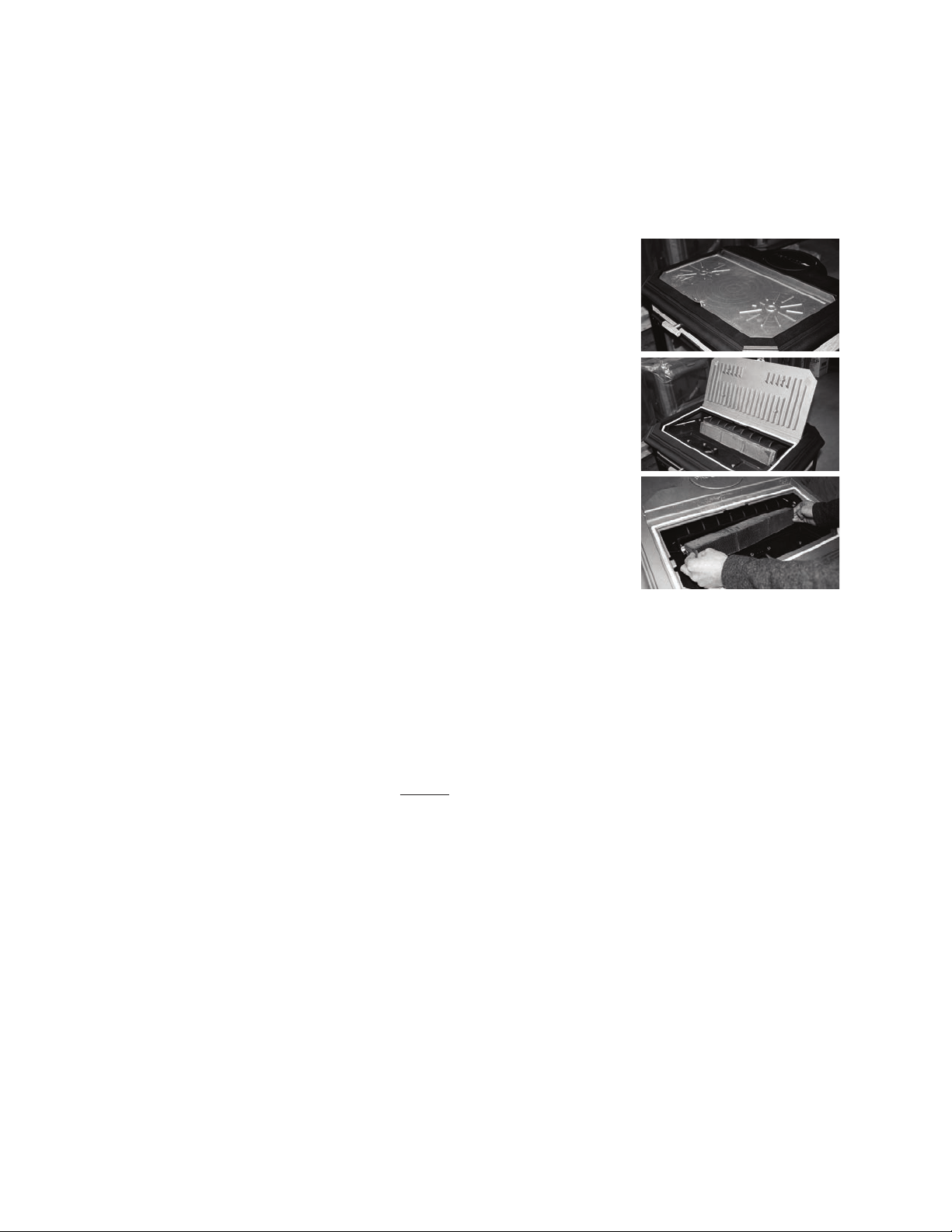
The stones can be removed completely from the stove, and the cast iron cook top will stand upright in
the rear channel to access the catalytic combustor below. This easy access makes cleaning and replacing
the combustor very user friendly.
19
The fall-away handle may be
used to operate the controls on
your stove when they are too
hot to handle safely.

Firewood
Your Woodstock Soapstone Stove is designed to burn seasoned, natural cordwood. Higher efficiency
and lower emissions generally result when burning air-dried seasoned hard woods, as compared to
green, freshly cut hard woods. It is perfectly fine to burn soft woods in your stove as long as they are
properly dried. Hard woods are preferable because they are typically denser than soft woods which
gives them a higher fuel value.
The moisture content of some trees may range as high as 50% – i.e., there is as much moisture in the
tree as there is wood. After wood has been stored for a year, the moisture content will usually range
from 15-25%. Splitting wood before it is stored will reduce drying time. Properly dried wood will
produce more heat, reduce the likelihood of water vapor condensing in the chimney forming creosote ,
and result in less pollution entering the air. It is safer and more efficient to burn dry or seasoned
hardwood than green or wet wood that smolders.
The advantages of burning dry wood are many. Dry wood is lighter, easier to split and easier to carry. It
is easier to light, produces more heat and generates less pollution. If you burn wet wood some of the
energy generated by the fire is used to drive moisture out of the wood, rather than producing heat for
you. Dry wood will maintain the highest combustor temperatures and burn the most efficiently.
Creosote is much less likely to form if you burn dry wood.
DO NOT BURN treated or painted wood, coal, garbage, cardboard,
solvents, colored paper, or trash in your Woodstock Soapstone Stove. Coal
and artificial logs burn much hotter than wood and could cause damage
through overheating to the cast iron or the soapstone panels. Burning
treated wood, garbage, solvents, colored paper or trash may result in the
release of toxic fumes and may poison or otherwise render the catalytic
combustor ineffective.
Burning cardboard, loose paper, and trash will add significantly to ash
and soot build-up, and it will not produce much heat. Fly ash from
improper fuel can also coat or plug the screens and combustor, causing
smoke spillage into the room. Under normal operating conditions, the
Woodstock Soapstone Stove is designed to last for generations. It is not,
however, designed for continuous over-firing, or firing with coal, artificial
logs or trash.
20
DO NOT BURN
• Treated Wood
• Coal
• Garbage
• Cardboard
• Solvents
• Colored Paper
• Trash
CAUTION
NEVER USE GASOLINE, LANTERN FUEL, KEROSENE, CHARCOAL LIGHTER FLUID, OR
SIMILAR LIQUIDS, TO START OR ‘FRESHEN UP’ A FIRE IN THIS STOVE. KEEP ALL SUCH
LIQUIDS WELL AWAY FROM THE STOVE WHILE IT IS IN USE.

CATALYTIC
COMBUSTORS
Here is how your catalytic combustor works.
The catalytic combustor is a stainless steel honeycomb with hundreds of cells. If you looked at the
inside of each cell with a microscope, you would see that the walls are uneven and filled with minute
nooks and crannies. Precious metals, such as platinum, are sprayed on the inside of these cells to coat all
of the nooks and crannies. This creates the largest possible surface area to interact with the wood smoke.
The catalytic combustor in your stove is very similar to the one in the exhaust system of your automobile
and works to achieve the same results - high efficiency and clean air!
When you first start a fire, you should bypass your catalytic combustor and let the smoke go directly
up the chimney. Once wood smoke reaches 500º F (about 10-15 minutes after re-establishing a strong
fire), it is hot enough to ignite the catalytic combustor. As the wood smoke passes through the cells in
the combustor, the smoke reacts with the precious metals which line the inside of the honeycomb and
both combustible gases and particles in the smoke ignite and burn. This “catalytic burn” reduces
emissions and also increases heat output from the stove.
Without a catalytic combustor, between 5% - 40% of the chemical energy contained in wood simply
escapes up the chimney when wood is burned. Energy laden gases are exhausted up the chimney where
they pollute the air or may condense on the inside of the chimney flue as creosote. The slower the burn,
without a catalytic combustor, the greater the amount of energy that is lost. A long smoldering fire is the
least efficient use of energy in wood, yet it produces lots of smoke, which is the fuel supply for the
catalytic combustor.
Most of the chemical compounds in wood smoke are combustible. The catalyst produces high
temperatures, which loosen the bonds of these chemical compounds and “burns” wood smoke. A stove
that “burns” these compounds and uses smoke as additional fuel will burn more efficiently and produce
more heat, while reducing creosote and air pollution at the same time. However, most stoves cannot
consistently produce temperatures high enough to burn cleanly, particularly during long burning times -
hence the need for a catalytic combustor.
Your catalytic combustor can get the most efficiency out of every piece of wood if it has three things:
temperature, turbulence, and time.
1. Temperature. The catalytic combustor can only start burning the gases in the wood smoke after the
smoke has reached at least 500 degrees F. Before the smoke reaches that temperature, it simply is
not hot enough to start the reaction at the combustor. This will result in an inefficient smoldering fire.
2. Turbulence. The wood smoke can interact best with the precious metals inside the honeycomb cells if
there is some variation in the air flow. Increased turbulence enables more of the wood smoke to
come into contact with more of the nooks and crannies in the honeycomb cells. The exhaust path as
well as the irregular surface of the combuster cells adds needed turbulence.
3. Time. Once the temperature and turbulence are achieved, the catalytic combustor just needs to have
enough time to burn all the gases in the wood smoke. For this reason, it is best to minimize the
amount of air you allow into the firebox once the combustor is ignited. Allowing too much air into
the firebox speeds up the rate at which the fire burns and allows more wood smoke to be consumed
by the secondary combustion system . The ideal air setting for a long catalytic burn allows enough
air to keep the wood burning and producing smoke.
With proper care, a new catalytic combustor will give years of fuel savings and lowered emissions.
By following some simple guidelines you can ensure maximum combustor performance and longevity.
Your catalytic combustor is designed to last for 12,000 -14,000 hours of use. You can ensure yourself of
getting the maximum life from your combustor by following these simple guidelines:
21
1) Burn only natural, well-seasoned wood.
2) Wait until the exhaust gases reach about 500 degrees F (internal temperature) before engaging the
catalytic combustor (about 10-15 minutes after re-establishing a strong fire).
3) Bypass the combustor before reloading and leave the bypass open for a few minutes after
reloading to raise the temperature in the stove.
4) Don’t overfire the stove.
5) Clean the combustor regularly. See instructions below.
You can also obtain a lot of useful information by visiting our website
(www.woodstove.com). Other very useful web sites on all aspects of wood
burning are (www.hearth.com), (www.woodheat.org) and (www.csia.org).
CSIA is the Chimney Safety Institute of America.
Inspection & Cleaning
Your stove comes with a new stainless steel combustor already installed.
The stainless combustor is a honeycomb foil block located under the top lid
of the Progress. Typical lifespan for a well maintained catalytic combustor
is 4-6 years. There are a few ways to determine if your combustor needs to
be cleaned. If you notice the smoke exiting your chimney is thicker and
darker in color the combustor may need cleaning. Additionally, if you
notice reduced draft or backpuffing, or performance and heat output has
diminished, then the combustor may not be working as efficiently as
designed.
STANDARD COMBUSTOR CLEANING HOW TO:
Tools needed: (1) work gloves and safety glasses; (2) soft bristled paint brush or vacuum cleaner
(preferably one designed for ash removal).
1. Be sure the fire is out and the stove is cold. If you are using a regular home vacuum, it is extremely
important that no hot ashes or embers be sucked into it as this could result in damage to the vacuum or
cause a serious fire. Remove the top stones from the stove. Lift the cast iron cook top and stand it up in
the rear channel.
2. Slide the combustor forward and out from under the cast iron surround. Brush or vacuum the
combustor thoroughly, from both sides. Do not use high pressure compressed air to clean the
combustor, as this could damage the reactive coating. Be sure to remove all fly ash from the combustor.
Inspect the gasket that the combustor rests against.
3. Slide the combustor back into position. Be sure it is seated firmly against the gasket behind it. Tuck
the narrow gasket between the combustor and the cast iron hood that surrounds it to ensure a tight fit.
VINEGAR & WATER CLEANING HOW TO:
The vinegar & distilled water cleaning is recommended 1-2 times during the heating season. The vinegar
is just acidic enough to remove any ash within the cells that may be masking the catalytic coating.
Materials needed: (1) work gloves and safety glasses; (2) spray bottle; (3) white vinegar; (4) distilled
water.
1. Be sure the fire is out and the stove is cold. Remove the top stones from the stove. Lift the cast iron
cook top and stand it up in the rear channel.
2. Slide the combustor forward and out from under the cast iron surround. Place the combustor onto
22

newspaper or an old towel. In the spray bottle prepare a 50/50 white vinegar & distilled water mixture.
3. Spray the 50/50 mixture through one side of the combustor and allow it to drain onto the
newspaper. Flip the combustor over and spray through the other side and allow it to drain.
4. Rinse the combustor with 100% distilled water to remove any remaining vinegar, allow the
combustor to dry before returning the combustor to the stove.
5. Return the combustor to the stove. Be sure that it is seated properly to the gasket behind.
6. Close the top lid.
Catalytic Combustor Replacement
If you feel that your catalytic combustor is not working properly, please contact Woodstock Soapstone
Company at 1-800-866-4344 for instructions regarding return and replacement. Accessing the catalyst in
your new Progress Hybrid Woodstove is simple, just remove the top soapstone pieces, raise the cast iron
cook top, and gently pull the combustor out of its housing. If it is difficult to pull out, there is a small
recess on each end of the stainless steel combustor. You can insert a small screwdriver into the hole and
pull the combustor forward, first one side and then the other.
Frequently Asked Questions
Q. How does the catalytic combustor work?
A. The catalytic combustor breaks the bonds that hold the chemicals contained in wood smoke
together. The result is that these chemicals begin to burn at temperatures of about 500 degrees F (the
normal range of exhaust gas.
temperatures). Without the catalytic combustor, wood smoke would have to be brought up to a
temperature of 1000 to 1200 degrees F in order to start to burn. A stove with a catalytic combustor will
generate up to 25% more heat from each piece of wood, thus reducing the amount of fuel used during
the year.
There are three advantages to burning the smoke created by burning wood. First, the smoke
becomes another source of fuel, giving you more heat from the same amount of wood. Second,
creosote causing materials will be burned up instead of being deposited in your chimney, reducing
the risk of a chimney fire. Third, air pollution will be drastically reduced.
Q. How can I tell if the catalytic combustor is working?
A. First - The best way to tell if the catalytic combustor is working is by observing the smoke coming
out of your chimney. If there is only a small amount of smoke, and/or it’s white in color, the
catalytic combustor is working. You will see significantly more smoke when the combustor is being
bypassed than when the smoke is being burned by the combustor.
Second - One very noticeable effect of a well functioning combustor is the high efficiency of your
stove. Catalytic combustors produce lots of heat, which the stove radiates into your home. If you
notice that the stove is producing less heat, or that a load of wood doesn’t provide as much warmth,
under similar circumstances, as it did before, it’s time to check the combustor. If and when the
catalyst ceases to function properly, the stove will produce noticeably less heat.
Third - Regular inspection of the connector pipe and chimney flue should show very little
accumulation of soot and creosote. Soot is typically brown and powdery when the combustor is
working properly. Heavy buildup of black sticky creosote may indicate the combustor is not
functioning or needs cleaning.
Q. How do I maintain my catalytic combustor?
23

A. Combustors should be inspected and cleaned if necessary every 4-6 weeks during the heating
season. When the stove is cool, the combustor can be cleaned by thoroughly vacuuming or brushing
both sides.
If the stove does not draft well when the catalytic combustor is engaged, then the combustor cells
themselves might be partially plugged with fly ash. If this is the case, follow the cleaning procedure
described in detail on page 19 of this manual.
Q. How will I know if the combustor is “worn out”?
A. There are three symptoms that will indicate that the catalyst in your stove may not be working:
First, your stove will generate noticeably less heat than it will when the catalyst is working. Second,
you will notice a dramatic increase in the amount of soot and/or creosote in your stovepipe or
chimney. Third, the color of the smoke produced by the stove will change. Smoke will appear black
or brownish, instead of clear, white smoke (almost steam) from a catalytic stove.
If you suspect that your catalyst is not working, let the stove cool down and clean the combustor
and try it again.
Q. Is it all right to burn my stove hot daily to clean any build up in my chimney system?
A. It is not necessary to burn your stove hot daily to burn off any creosote build up in the chimney.
This function is performed by the catalytic combustor. It is there to reduce the emissions from the
stove that contribute to deposits in the connector pipe and chimney flue.
View more frequently asked questions and articles at our web site www.woodstove.com. Other very
useful websites on all aspects of wood burning are www.hearth.com, www.woodheat.org, and
www.csia.org. CSIA is the Chimney Safety Institute of America.
TWO OTHER IMPORTANT POINTS REGARDING CATALYTIC COMBUSTORS:
1) The combustor uses wood smoke as fuel. Most smoke is created in the early stages of the burn cycle.
When a bed of coals is all that remains of your wood, there is little smoke left to fuel the combustor,
and it will no longer create substantial amounts of heat. Hence, the temperatures on the surface
thermometer tend to fall toward the end of the burn, even though the firebox is full of hot coals.
This does not mean that you have to reload the stove or open the bypass. Let the hot coals burn
down to ashes.
2) Since the combustor blocks the path of exiting smoke, it can reduce the draft in your stove. When
draft is reduced by warm or rainy weather, open the bypass damper longer when starting the stove
to create more draft.
CATALYTIC COMBUSTOR WARRANTY
The catalytic combustor in your Progress Hybrid Woodstove is fully warranted for three years from the
date of purchase against any defect in workmanship or materials that prevent the combustor from func-
tioning when installed and operated properly. The catalytic combustor is additionally warranted for three
years from the date of purchase for any deterioration in the stainless steel substrate material. For instruc-
tions regarding return or replacement of the catalytic combustor, please contact:
Woodstock Soapstone Company, Inc.
66 Airpark Road
West Lebanon, NH 03784
Phone: 1-800-866-4344 • Web: www.woodstove.com
24

MAINTENANCE
Stove Cleaning
The ornamental cast iron frame of the Woodstock Soapstone Stove is painted with two coats of high
temperature stove paint. Under normal operating conditions, this paint will not peel or blister. We
suggest cleaning by dusting with a soft brush or vacuuming with a brush attachment when the stove is
cold. If the iron castings are exposed to moisture for a long period of time they may rust. If this
happens, brush the affected area until clean with either a short wire brush or medium steel wool and
then touch-up with high temperature stove paint, which is available from Woodstock Soapstone
Company.
Soapstone is a very soft mineral and the polished exterior surfaces can be scratched. Scratches may be
easily removed by sanding lightly with medium steel wool or 120 grit sandpaper. The surface may then
be buffed with 400 grit sandpaper or fine steel wool. Remove dust created by sanding with a vacuum
cleaner; a damp cloth will simply spread it around. Be sure the stove is cold before you clean it.
Glass Cleaning
We use ceramic glass in our stoves because it is resistant to both impact and thermal shock. The panes
of ceramic glass installed in the stove fronts have full gaskets around the perimeter so there is no contact
between the glass and the cast iron frame.
There are two panes of glass at the front of each stove, with an air-space between the two panes. This
“thermalpane” arrangement helps keep the temperature on the inside of the glass higher and prevents
condensation and soot from accumulating. The Progress Hybrid has a large glass area with an
“airwash” design in which the primary air supply washes over the front glass to assist in keeping the
glass free of ash and soot.
The glass may soot up the first time you use the stove (from condensation already inside the stove).
Don’t be alarmed! Usually, as soon as you build up adequate temperature with a hot fire, the glass will
clean itself. The residue will burn off, and it will stay clean. Soot accumulation on the inside of the glass
is more likely in the spring and fall, when temperatures are very mild and you are less likely to maintain
a hot fire.
To clean the inside of the glass or wipe off fly ash, we recommend that you use a brush with soft
bristles (like a paintbrush). You may clean heavy soot from the glass with very fine steel wool (0000
grade), but first, be sure the fire is out; and second, be sure that the glass has cooled to room temperature
before you clean it. DO NOT ATTEMPT TO CLEAN HOT GLASS.
Gasket Replacement
There are five areas on your stove where you should check the gasket routinely: (1) on the side door,
(2) under the cast iron cooktop, (3) under the catalytic bypass damper, (4) behind the catalytic combustor,
(5) and the ashpan door (models purchased with the ashpan). These five gaskets are the most important
for maintaining high efficiency and clean burning. Close a slip of paper in these gasketed areas. There
should be resistance as you pull the paper out. If there is any evidence of deterioration and/or leaking in
any of these areas or if any of the gasket material in the stove becomes worn or frayed, it should be
replaced. Please contact Woodstock Soapstone Company for replacement gasket and replacement
instructions.
The sizes of all the gaskets on your Progress Hybrid woodstove are included in the parts list on page
31-34 of this manual.
2

Routine Checks And End of Season Maintenance
Every few weeks of operation we recommend checking the chimney connector (stovepipe) and
combustor (see combustor section) and cleaning, if necessary.
When the weather warms up and the burning season is over, it is a good idea to do a thorough spring
cleaning and inspection of your stove and chimney system. We recommend an annual inspection and
cleaning by a certified chimney sweep who has the tools and knowledge to inspect the whole system,
from top to bottom. Chimney safety is an important part of responsible wood burning . The best way to
gain confidence in the safety of your Progress Hybrid Woodstove is to have it serviced and inspected
once a year by a professional chimney sweep. The Chimney Safety Institute of America maintains a
database of certified sweeps nationwide. Go to their website www.csia.org to find a professional in your
area.
If you live in a climate with warm, humid summer weather, your stove may collect moisture from
warm, moist, chimney downdrafts during the summer. If this happens, the moisture may wick through
the gasket between the cast iron and the soapstone panels, and appear as discoloration around the edge
of the exterior soapstone. If this happens, you can remove any discoloration with fine steel wool. One
way to reduce the likelihood of this happening is to block the flue exit in the stove with fiberglass
insulation at the end of the heating season. This will help prevent downdrafts and humidity from
entering the stove. (You’ll have to be careful to remember to remove the insulation before you light the
stove again in the fall!)
Creosote- Formation and Need for Removal
When wood is burned too slowly, it produces tar and other organic vapors, which combine with
expelled moisture to form creosote. The creosote vapors condense in the relatively cool chimney flue of a
slow burning fire. As a result, creosote residue accumulates on the flue lining. When ignited, this
creosote makes an extremely hot fire.
The chimney connector and chimney should be inspected at least once every two months during the
heating season to determine if creosote buildup has occurred. If creosote has accumulated it should be
removed to reduce the risk of a chimney fire. Cleaning the combustor regularly will also greatly reduce
creosote buildup. Under certain conditions, creosote can form rapidly.
The most likely conditions for creosote to occur are: (1) when a large number of small pieces of wood
are added to a hot bed of coals and the damper is then completely closed; (2) extremely long, smoldering
fires, and; (3) burning wet or green wood.
Lack of combustion air and smoldering fires usually result in dense smoke and low stack temperatures
in the chimney connector and the chimney. Wet or green wood can also produce dense smoke and
excessive water vapor, which can quickly lead to creosote buildup.
Creosote will accumulate faster in exterior chimneys than interior chimneys because of colder outside
temperatures.
There are three stages of creosote build-up. The first is a flaky, crystal-like accumulation which can be
removed with a brush. The second is a tar like coating. The third is a hard, glossy enamel like coating
that is difficult to penetrate. If your chimney is heavily coated with tar or enamel like creosote, we
recommend that you consult with an experienced chimney sweep about removal and prevention.
PREVENTION: Without question, the best way to treat creosote is to prevent its accumulation. In
order to reduce the danger of accumulation, we recommend the following:
1. Burn only properly dried firewood. Dry wood burns hotter, cleaner, and expels less moisture to
condense.
2. Use the catalytic combustor properly. It can reduce possible creosote accumulation by as much as
90% and improve stove efficiency at the same time. Be sure to read the section on catalytic
2

combustors on pages 20-23.
3. Never operate your stove for extended periods of time with the draft control completely closed.
Both the wood fire and the catalytic combustor need oxygen to burn efficiently.
4. Re-establish a hot fire, and re-ignite the combustor after every reloading by opening the primary
air control for about 10 minutes.
5. Check the catalytic combustor output. Use the thermometer provided with the stove to be sure
that the catalytic combustor is igniting properly when you kindle a fire or reload the stove. The
temperatures on the stove top should rise noticeably when the catalytic combustor is engaged.
6. Avoid long, smoldering fires. Again, the catalytic combustor is critical here. Hot firebox
temperatures (with the stove top thermometer in the 400-600
0
F range) will produce more complete
combustion and maintain proper catalytic activity.
2

28
TROUBLESHOOTING GUIDE
Problem
Stove smokes
Back Puffing or
sudden internal
ignitions
Combustor not
glowing
Stove burning too
hot or fast
Possible Cause
Operating technique
Blocked Chimney
Blocked outside airduct
Oversized chimney
Chimney too short
More than one appliance vented
into flue
Operating technique
Burn rate too low
Chimney down draft
Combustor plugged
Tight house
Late stage of burn
Ashpan Door is Open
Excessive draft
Extra tall chimney
High wind or hilltop location
Solutions
Open bypass and air damper prior to reloading
stove
Examine chimney and stovepipe for blockage and
creosote accumulations. Check spark arrestor screen
on your cap, if you have one.
Check the outside inlet for blockage caused by
snow, debris, or insects.
Reline chimney to appropriate size.
Add height (industry standard is 15ft or more).
Disconnect other appliances, seal openings appro-
priately.
Open bypass and air dampers before opening to
reload and keep it open a few minutes after reload-
ing.
Open air damper to allow for hotter burn.
In high wind areas, a specially designed wind cap
may be necessary.
Clean combustor of accumulated fly ash.
Dedicated air supply with outside air adaptor
attachment to stove.
Combustor does not need to be glowing to be work-
ing. Check smoke exiting chimney to help deter-
mine if combustor is working properly.
Close ash door securely, check ash door
gasket,check clean out door or cap secure.
Adjust air damper to lower setting.
Consider installing pipe damper
Install wind cap on top of chimney

29
Insufficient Heat
Acrid odor during
initial burn
Window Dirty
Poor quality or green wood
Blocked outside air duct
Heat going up chimney
Paint and/or window gasket
curing
First start up fire
Airflow restricted
Smoldering fire
Use only well-seasoned wood (dried at least one
year). Test with kiln dried wood.
Check outside air duct for blockage
Test with thermometer on 1st section of
stovepipe– temps should drop below 300
degrees F when combustor is engaged.
Open windows until paint or gasket is cured.
Check gap for air guide at top of stove window
inside stove. There should be a 17/64” in gap
between glass and edge of cast iron plate. A
smaller gap due to ash build up could restrict
air flow and cause the window to soot up.
Open-air damper in small increments until some
slow flames appear. Run hot fire to burn smoke
off the glass, or remove build up with glass
cleaner when stove is cold.
Green or wet wood. Burn drier wood, or open
air damper slightly for a hotter burn. (see above)
Is my Combustor still working?
Your catalytic combustor is viable for 12,000 to 14,000 burn hours. This translates, roughly, into a life span of 4 -
6 years. If the catalytic coating is not working as it should, it is not burning the gas vapors in the smoke and
therefore, the smoke exiting your chimney will be darker in color. If your draft is sluggish and you have ruled
out any draft related issues in the venting or in the wood supply, your combustor may not be burning the smoke
vapors and too much volume is trying to pass through the honey-comb at one time. If heat output is diminished,
and any other factors are ruled out, that may also be a sign that the catalytic combustor is not burning the smoke
vapors, therefore not extracting maximum heat from available btu’s in the wood you are burning.

SAFETY
Overview
To gain maximum enjoyment and benefit from your stove, you must have a safe installation. All guidelines
found in this manual should be adhered to. All local and national building codes need to be followed. Having a
certified installer perform all connections to an inspected chimney system is strongly advised. If you choose to
perform any or all of this work yourself, it must be inspected by either a Certified Wood Stove Specialist or a
Certified Chimney Specialist.
You will often find the local Fire Department to be very knowledgeable. They may inspect your house for prop-
er warning devices, fire extinquishers and evacuation routes. Keep their phone number handy. Although many
communities utilize Fire Department personnel for woodstove installation inspections, they are not usually
trained as combustion venting specialists. Generally, you are best advised to use a certified specialist. The sense
of security that comes with a properly installed and maintained system is worth far more than its cost.
Installation
Your Woodstock Soapstone Stove has been thoroughly tested and listed to UL #1482 by an independent testing
laboratory. UL #1482 is the standard for testing solid fuel appliances and is universally recognized by all nation-
al building regulatory agencies, (SBCC, BOCA, ICBO) and individual states. Your woodstove is a safe product,
but it must be installed in accordance with the instructions in this manual. Woodstoves themselves rarely cause
fires, but improper installation or careless operation are often to blame.
Follow the guidelines in the Installation chapter of this manual with regard to:
• Proper chimney and connector pipe
• Clearances to combustible surfaces and objects
• Floor protection
Smoke and the Chimney
According to www.woodheat.org, “The chimney is the engine that drives a wood heat system”. To have a safe
system you must have:
• The correct type of chimney
• The correct size of chimney
• Correct location inside the house
• A properly installed system
Smoke spilling into the living space when starting a fire is an inconvenience. Smoke spilling into the house
when you are away or asleep can be a major problem. In order to have all the smoke go up the chimney all the
time, the chimney must have positive draft. Ideally, this draft is between 10-18 pascals, or .04-.07 inches water
column, a pressure measurement, when there is no fire in the stove. A certified installer can perform a simple
draft test for this.
Heat
Your stove is HOT to the touch! Utilizing the fall away handle and use of heat resistant or insulated stove gloves
can prevent serious burns when opening or closing the door, ash pan or lid of your stove.
Ash removal
Convenient and safe ash removal is a necessity for trouble free wood burning. An ash removal container should
have:
•A comfortably large capacity
•Good stability
30

•A top that closes securely and will not fall off
•Legs or other means of preventing downward heat flow
•A design that prevents spilling when loading
Ashes should never be dumped into a combustible container, such as a cardboard box, and an ash con-
tainer should never be set on a combustible floor. Hot embers in the ashes can often stay viable for 36
hours or longer after removal from your stove.
Precautions
•Smoke detectors: A smoke detector is inexpensive insurance and is required by most localities. They
can either work on batteries, or can be hard-wired into your electrical system. If you have battery operat-
ed detectors, it is a good idea to replace batteries on an annual basis (i.e.: every New Year’s day, or 4th of
July, etc). They will sound an audible alarm in the event of the presence of smoke. Smoke will almost
always precede a wood-fueled fire.
•Fire Extinguisher: If you burn wood, you should have at least one ABC dry chemical extinguisher.
The chemical extinguisher is preferable to water because the application of cold water to hot metal stove
pipes can cause metal parts to buckle or crack, thereby releasing more fuel to the fire.
•Carbon Monoxide Detector: These operate in a manner similar to smoke detectors but are usually
user-calibrated and record minute quantities on a digital readout before sounding an audible alarm. The
chances of carbon monoxide being created and escaping from your properly installed and operated stove
are miniscule. You may have other vented appliances in your home that could be potential problems.
The investment in a high quality carbon monoxide detector is well worth its cost in the peace of mind it
affords.
•Chimney inspection: Your connector pipe and chimney or chimney pipe should be inspected at reg-
ular intervals. Examine the connector pipe for creosote, corrosion, loose seams, or excessive soot. Clean
and replace as necessary. The chimney or chimney pipe should be cleaned and checked by a certified
specialist once a year. A small mirror held at the cleanout door of a masonry chimney will be helpful. For
a class A prefabricated metal pipe, some disassembly is usually required.
Emergency Procedures In The Event of a Chimney Fire:
If you have a chimney fire or runaway fire follow these safety precautions:
1. Close the draft damper immediately, with a slow and even motion. This cuts off the supply of oxy-
gen to the stove.
2. Call the fire department immediately.
3. Get everyone out of the house. One adult should stay in the house to check for sparks and signs of
fire. Those outside should watch the roof for signs of fire.
4. If there is a danger of a fire, discharge the fire extinguisher into the stove. Do not pour or spray
water directly into the chimney as rapid contraction caused by the application of cold water could
cause the tile liner in the chimney to crack.
5. After the fire is out, check the stove, chimney connector and chimney carefully for signs of damage.
The entire system should be thoroughly inspected by a certified chimney professional.
Note: Chimney fires must be put out from the bottom. The entire system must be air tight to suffocate a
fire; hence the importance of having a tight cover on the chimney cleanout and not venting two appli-
ances into a single flue.
The length of time it takes to bring a chimney fire under control depends on the amount of fuel in the
stove, the rate at which it is burning and the amount of oxygen available to it. The faster it is brought
under control the less severe any damage is likely to be.

32
Cast Iron Parts
P-301 Base
P-302 Leg
P-303 Cast iron cook top
P-307 Top
P-309 Back
P-310 Front
P-311 Fettle/Andirons
P-313-R Right side doorframe
P-313-L Left side doorframe
P-314 Door
P-315 Door stone retainer
P-316 Door latch
P-318-A Bottom fill plate
P-319 Ash grate
P-320 Left air channel
P-321 Right air channel
P-322 Fireback dome (kettle)
P-323 Front air manifold/wash
P-324 Stone retainer – non-door
side
P-325 Catalyst base – bypass plate
P-326 Catalyst top
P-327S Bypass door
P-329 Fall-Away Handle
P-330 Corner
P-331 Flue cover plate
P-332 Flue collar
P-333 Escutcheon
All cast iron parts designed by
Woodstock Soapstone Company
Steel/Sheet Metal Parts
K-533- Stainless Steel Catalyst
2.5H” x 17”L x 2.5”D x 49 cpsi
W-312 Window clips
P-318B Bottom Heat Shield, fill
plate type
K-334a Air Damper Assembly
P-353P Stone edge liner
P-363 Fireback
P-364L Left side fireback retainer
P-364-R Right side fireback
retainer
P-364-B Fireback retainer, back edge
P-365 Front over glass
P-366 Front under glass
P-367 Left side – non-door style
P-368 Left side – door style
P-369 Right side – door style
P-370 Right side – non-door
style
P-371 Bypass hold down
P-372 Bypass lift guide
P-374 Bypass activation shaft
P-375 Bypass handle
P-376 Rear stone retainer
P-377 Int. Corner stone retainer
P-378 Top heat shield
P-386 Damper knob
P-387 Door ring handle
K-388 Top stone medallion
P-390 Door handle spacer
P-391 Cook top handle
All steel parts manufactured by
Woodstock Soapstone Company
Soapstone Parts
#pcs
P-347 Int. front corner 2
P-348 Int. right rear corner 2
P-350 Ext. full side 1
P-351 Ext. over-the-door 1
P-352a Ext. over-the-front 1
P-352b Ext. under-the-front 1
P-353 Top stone 1
P-354 Corner 4
P-355 Ext. door 1
P-356a Int. upper side (front) 1
P-357a Int. upper side (rear) 1
P-358 Int. bricks 8
P-359 Int. back (middle) 1
P-360 Int. under-the-door 1
P-361 Top stone ctr. 1
P-361L Top stone left 1
P-361R Top stone right 1
All soapstone parts cut and fabricated
by Woodstock Soapstone Company
Other:
P-2500 UL/EPA Cert label
P-2491 Ash door caution label
P-2472 Tie rod for PH
P-2802 Pallet for PH
P-385E Window glass
P-385E-IR Int. glass
10” Probe Thermometer
Surface Thermometer
Ash pan assembly:
P-335 Ash pan
P-336 Ash pan cover
P-337 Ash pan holder
P-338 Ash door inner
P-339 Ash door outer
P-340 Ash door handle
P-341 Ash box bottom heat
shield
Rear heat shield assembly:
K-384 Rear heat kit
Commonly Replaced Gaskets
Part #
Desc. Location Density
21050 .187 Round Behind Air Damper Assembly LD2
21085 .250 Round Catalytic Combustor Seal LD2 density
21085 .375 MX Round Under Cooktop (P-303) LD2 density
21085 .250 Round Flue Cover Plate LD2 density
21085 .250 Round Flue Collar LD2 density
21085 .250 Round Under Bypass Door LD2 density
21063 .500G Round Loading Door Gasket LD1 density
21158 .500G Round Ash door inside LD1 density
PROGRESS 209a PARTS LIST

33
MODEL
THICKNESS HEIGHT WIDTH
EXTERIOR
W-350 FULL SIDE 0.75 20.396 13.039
W-351 OVER DOOR 0.75 5.458 13.039
W-352a OVER FRONT 0.75 3.296 20.539
W-352b UNDER FRONT 0.75 3.075 20.539
W-353 TOP 1.125 12.494 22.958
W-354 CORNER (4) 0.75 20.396 3.092
INTERIOR
W-355 DOOR 0.75 9.64 7.51
W-356a UPPER SIDE FRONT 1.125 5.868 5.84
W-357a UPPER SIDE REAR 1.125 4.304 6.984
W-358 BRICKS (8) 1.125 8.535 3.2
W-359 BACK MIDDLE 1.125 8.535 5.7
W-360 UNDER DOOR 1.125 2.22 12.85
MODEL 209a SOAPSTONE GUIDE
EXTERIOR SOAPSTONE
INTERIOR SOAPSTONE
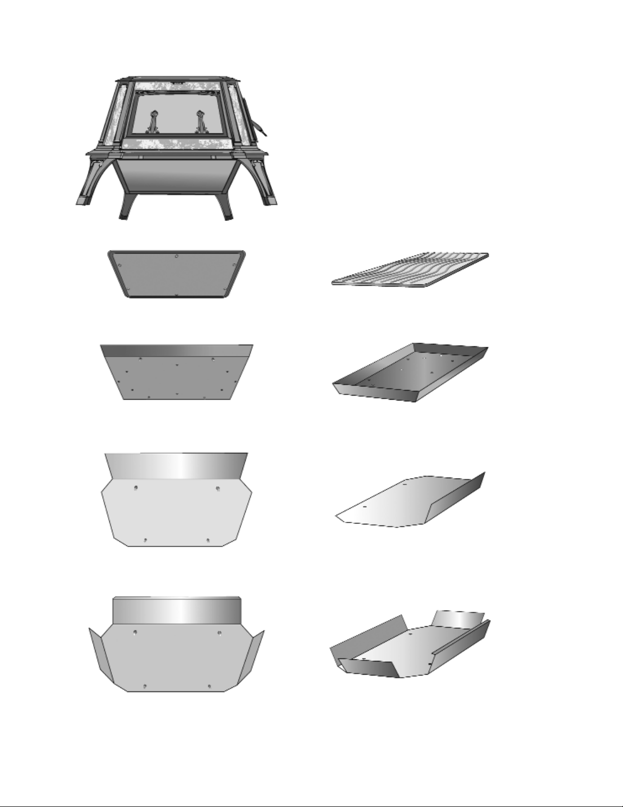
BOTTOM HEAT
SHIELD DIAGRAM
Bottom fill plate
P-318
Shield #1
P-318b
Shield #2
P-318c
Shield #3
P-318d
NOTE: The fill plate must be installed
inside the firebox before the bottom heat
shields are attached.
Detailed instructions and hardware are included with the bottom heat shield kit. If you
have any installation questions, please call us toll free at 1-800-866-4344
34
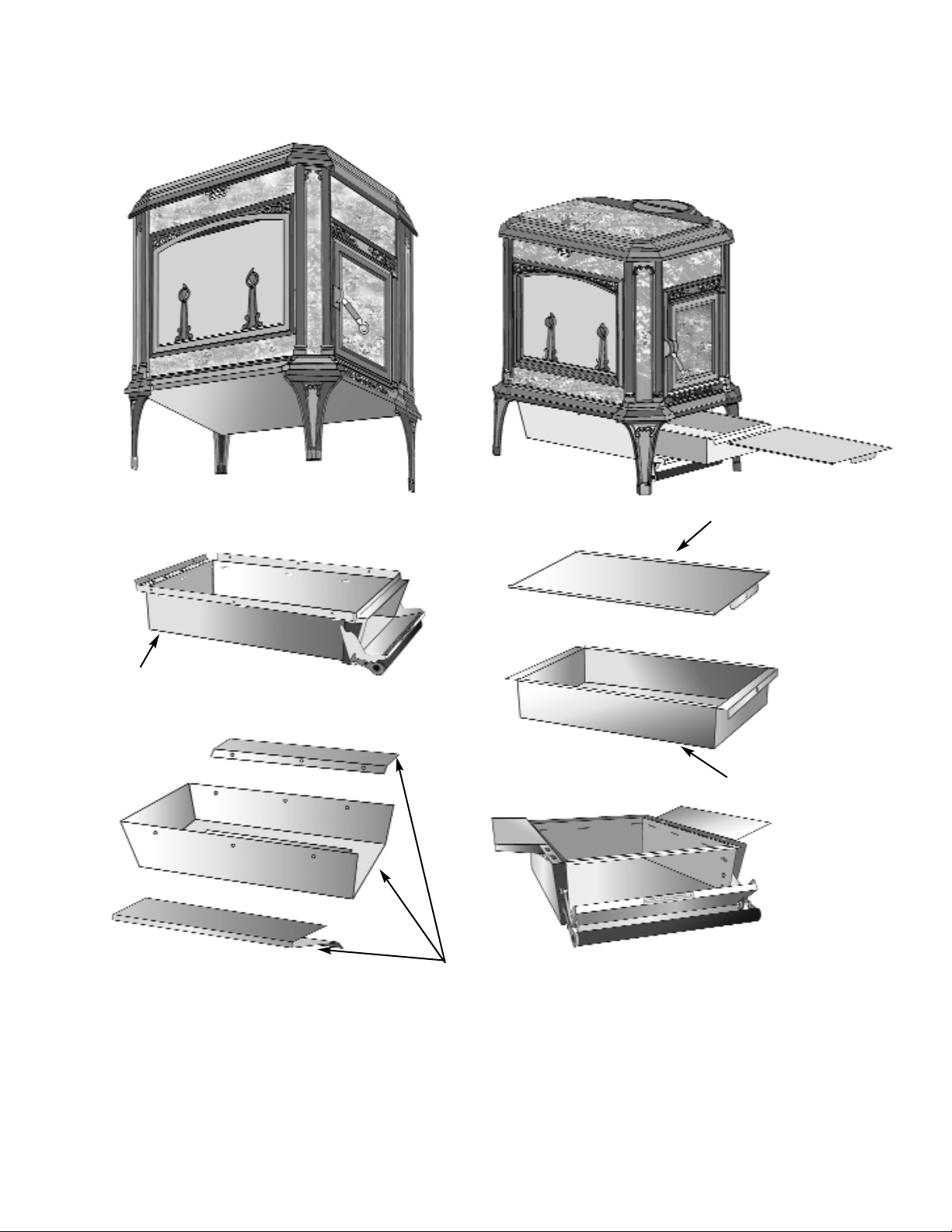
Detailed instructions and hardware are included with the ash pan kit. If you have any
installation questions, please call us toll free at 1-800-866-4344
ASH PAN DIAGRAM
Ash Pan
P-335
Ash Pan Cover
P-336
Ash Pan Holder
P-337
Ash box bottom
heat shield
P-341
35
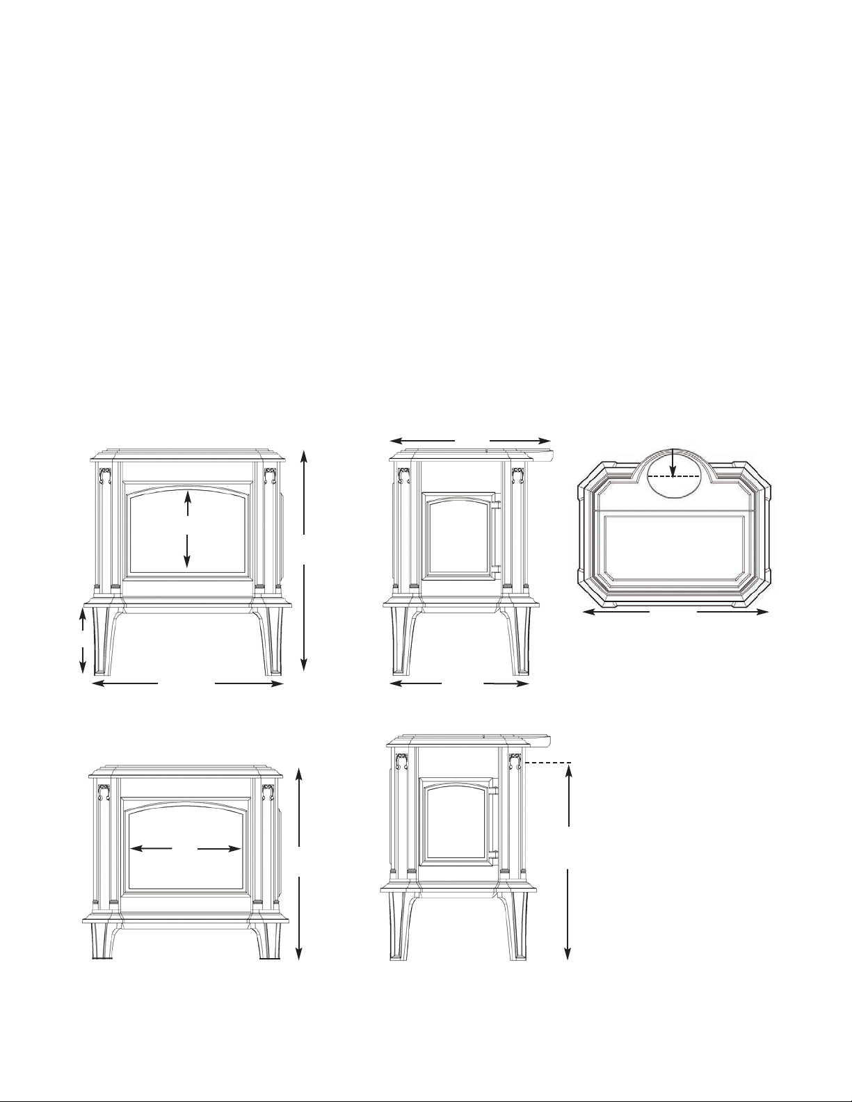
DIMENSIONS & SPECIFICATIONS
H x W x D (10” Standard Legs). . . . . 33.5”x30.5”x25”
HxWxD (5” Short Legs). . . . . . . . . . . . 28.5”x30.5”x25”
Ash pan unavailable with short legs
EPA 2020 Certified. . . . . . . . . . . . . . . . . . . . . . . . . . . . . Yes
Listed to UL 1482. . . . . . . . . . . . . . . . . . . . . . . . . . . . . . Yes
Flue Exit. . . . . . . . . . . . . . . . . . . . . . . . . . . . . . Top or Back
EPA Cordwood Emissions Rating . . . 0.63 grams/hr
Flue Size. . . . . . . . . . . . . . . . . . . . . . . . . . . . . . . . . . . . . . . . 6”
EPA HHV Efficiency . . . . . . . . . . . . . . . . . . . . . . . . 78.5%
EPA LHV Efficiency . . . . . . . . . . . . . . . . . . . . . . . . 84.4%
Flue Height to Center (Standard Legs). . . . . . . 27.75”
Catalytic Combustor & Secondary Air . . . . Standard
Flue Height to Center (Short Legs). . . . . . . . . . . 22.75”
Bottom Heat Shield. . . . . . . . . . . . . . . . . . . . . . . Standard
Weight. . . . . . . . . . . . . . . . . . . . . . . . . . . . . . . . . . . . 700 lbs.
Ash Pan. . . . . . . . . . . . . . . . . . . . . . . . . . . . . . . . . . Optional
Loading Door. . . . . . . . . . . . . . . . . . . . . . . . Right or Left
Back Clearance (no protection). . . . . . . . . . . . . . . . . . 36”
Loading Door Size (HxW). . . . . . . . . . . . . . . . . . . 11”x9”
Back Clearance (w/Heat Shield Kit) . . . . . . . . . . . . 7”
Draft Control. . . . . . . . . . . . . . . . . . . . . . . . . . . . . . Manual
Side Clearance. . . . . . . . . . . . . . . . . . . . . . . . . . . . . . . . . 24”
Wood Length (Maximum). . . . . . . . . . . . . . . . . . . . . . 22”
Firebox Size. . . . . . . . . . . . . . . . . . . . . . . . . . . 2.8 Cubic ft.
Viewing Window (HxW). . . . . . . . . . . . . . . 12.25” x 16”
Burn Time. . . . . . . . . . . . . . . . . . . . . . . . . . . . . . . . 8-16 hrs.
Heat Output Range. . . . . . . . . 13,149-47,220 BTU/hr
Area Heated. . . . . . . . . . . . . . . . . . . . . 1,600-2,200 sq. ft.
33.5”
Progress with Standard Legs
25”
10”
30.5”
20.5”
4.5”
Centerline to rear 6” flue
27.75” with 10” Legs
22.75” with 5” Legs
28.375”
Progress with Short Legs
28.5”
Centerline
6”rear flue exit
12.25”
16”