MODEL 512M
THROUGH-THE-WALL VENTILATOR
WARNING
TO REDUCE THE RISK OF FIRE, ELECTRIC SHOCK, OR INJURY
TO PERSONS, OBSERVE THE FOLLOWING:
1. Use this unit only in the manner intended by the manufacturer. If
you have questions, contact the manufacturer at the address or
telephone number listed below the warranty.
2. Before servicing or cleaning unit, switch power off at service panel
and lock the service disconnecting means to prevent power from
being switched on accidentally. When the service disconnecting
means cannot be locked, securely fasten a prominent warning
device, such as a tag, to the service panel.
3. Installation work and electrical wiring must be done by qualified
person(s) in accordance with all applicable codes and standards,
including fire-rated construction codes and standards.
4. Sufficient air is needed for proper combustion and exhausting of
gases through the flue (chimney) of fueling equipment to prevent
backdrafting. Follow the heating equipment manufacturer’s guide-
line and safety standards such as those published by the National
Fire Protection Association (NFPA), and the American Society for
Heating, Refrigeration and Air Conditioning Engineers (ASHRAE),
and the local code authorities.
WARNING
5. When cutting or drilling into wall or ceiling, do not damage electrical
wiring and other hidden utilities.
6. Ducted fans must always be vented to the outdoors.
7. To reduce the risk of fire, use only metal ductwork.
8. This unit must be grounded.
INSTALL THE VENTILATOR
WARNING: WHEN CUTTING OR DRILLING INTO WALL,
DO NOT CUT EXISTING ELECTRICAL WIRING.
CAUTION: Do not mount the ventilator above a cooking
surface.
CAUTION: Measure and mark the center of wall opening
on inside and outside walls before cutting opening.
1. Cut a 6-3/8" diameter opening in the outside wall.
2. If using the adjustable duct, cut a 6-3/8" diameter opening in the
inside wall. If not, cut a 6-1/8" diameter opening in the inside wall.
3. Unplug motor, loosen screw and remove electrical wiring box
cover.
4. Push electrical wiring box into housing and lift out.
Note: For easier removal of wiring box, remove the motor assembly.
Loosen the mounting screws and rotate the motor assembly clockwise.
READ AND SAVE THESE INSTRUCTIONS
VENTILATOR
GRILLE
WALL
CAP
ADJUSTABLE
DUCT
5¼" TO 10"
CAUTION
1. For general ventilating use only. Do not use to exhaust hazardous
or explosive materials and vapors.
2. To avoid motor bearing damage and noisy and/or unbalanced
impellers, keep drywall spray, construction dust, etc. off power unit.
3. Please read specification label on product for further information
and requirements.
4. The wearing of safety glasses and gloves is recommended when
installing, maintaining or cleaning the unit to reduce the risk of
injury that could be caused by the presence of thin metal and/or
high moving parts.
If this fan is to be used to ventilate a garage:
A. Use only in single family, residential garages
B. Install in a GFCI protected branch circuit
C. To help offset the risk posed by high concentrations of vapors from
paints, glues, solvents, and fuels, install fan at least 18 inches
(0.5m) above the floor
D. NEVER run a vehicle or use a fuel burning appliance inside of
a garage. Deadly levels of carbon monoxide can build up in the
area. Using this garage fan, or opening windows and doors, will
NOT supply enough fresh air to eliminate the danger.
E. Run regularly if exposed to salty air environments
F. Extra cleaning may be required due to possible dirty surroundings
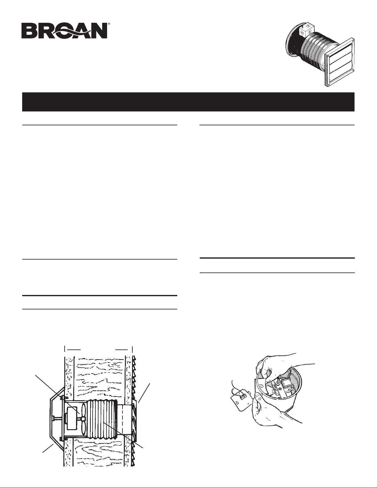
PLAN THE INSTALLATION
The ventilator can be installed in outside walls walls up to 10" thick. Walls
less than 6" thick will not use the adjustable duct. Choose a location
with no obstructions, such as wall studs, plumbing or electrical wiring.
The ventilator can be controlled using a wall switch or speed control
(available separately).
WIRING
BOX
WHITE
GROUND
BLACK
120/127 VAC
POWER CABLE
TAPE HERE
ATTACH GRILLE
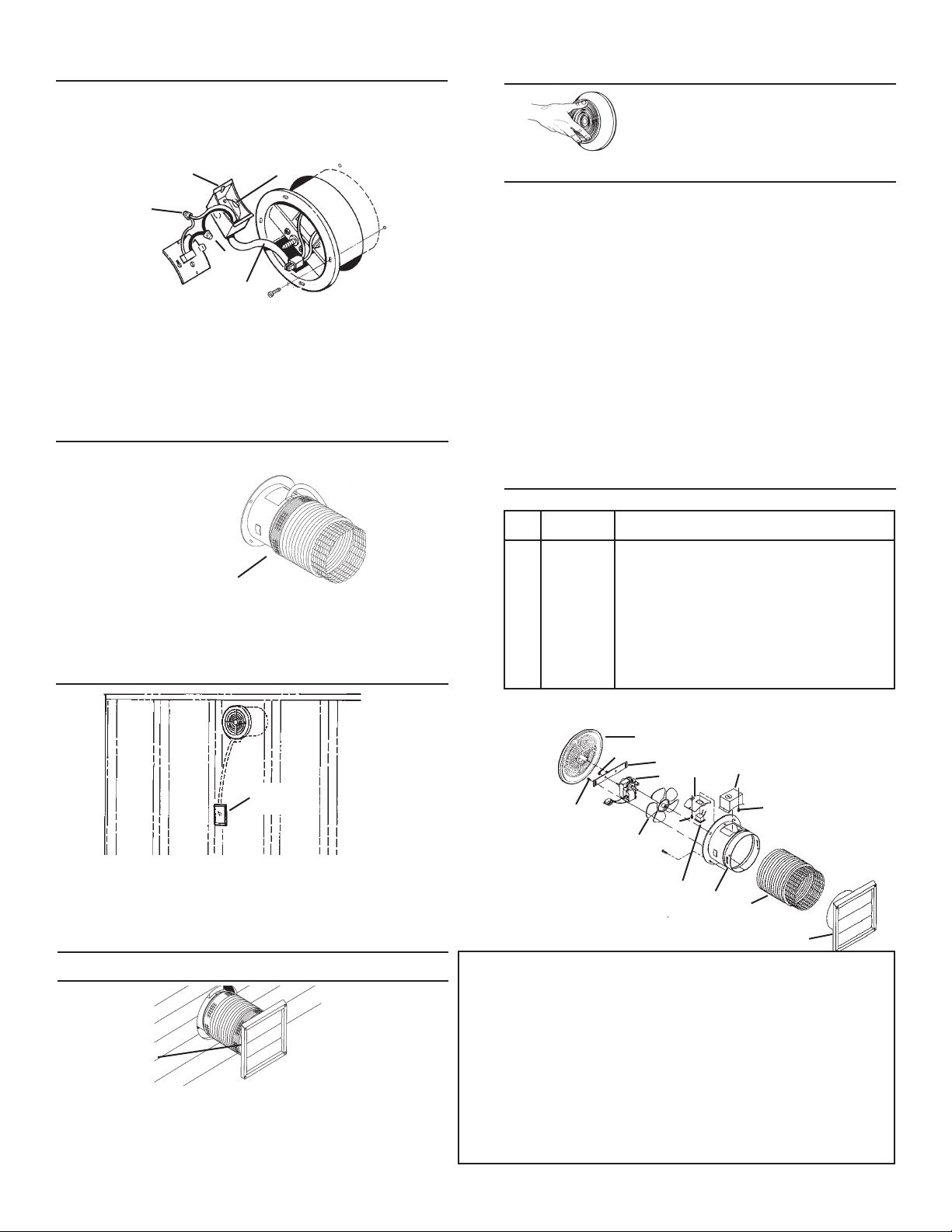
1. Attach power cable to electrical wiring box and switch box using
the proper connector for the type of cable being used.
2. Make electrical connections. Connect black to black, white to
white and bare or green wire to electrical wiring box using the
green ground screw.
CONNECT THE DUCT
(FOR WALLS 6" TO 10" THICK ONLY - INCLUDING INSIDE AND OUTSIDE
WALL COVERINGS)
1. Stretch the adjustable duct, slide it over the housing and tape it
in place. (You may need to shorten non-tapered end of flexible
duct to fit.)
INSTALL VENTILATOR IN WALL
1. Place ventilator into wall opening. Re-install electrical wiring box
and cover. Plug motor into receptacle in wiring box cover.
2. Fasten ventilator to inside wall with appropriate screws.
1. From outside, slip adjustable duct into wall cap and tape the joint.
2. Compress the excess duct back into the opening by positioning the
wall cap against the outside wall.
3. Fasten wall cap to outside wall and caulk around the edges.
ON/OFF
SWITCH
TAPE HERE
ATTACH WALL CAP
(FOLLOW STEPS 1 & 2 ONLY IF ADJUSTABLE DUCT IS USED)
BROAN-NUTONE ONE YEAR LIMITED WARRANTY
Broan-NuTone warrants to the original consumer purchaser of its products that such products will be free from defects in
materials or workmanship for a period of one year from the date of original purchase. THERE ARE NO OTHER WARRAN-
TIES, EXPRESS OR IMPLIED, INCLUDING, BUT NOT LIMITED TO, IMPLIED WARRANTIES OF MERCHANTABILITY OR
FITNESS FOR A PARTICULAR PURPOSE.
During this one-year period, Broan-NuTone will, at its option, repair or replace, without charge, any product or part which is
found to be defective under normal use and service.
THIS WARRANTY DOES NOT EXTEND TO FLUORESCENT LAMP STARTERS AND TUBES. This warranty does not cover
(a) normal maintenance and service or (b) any products or parts which have been subject to misuse, negligence, accident,
improper maintenance or repair (other than by Broan-NuTone), faulty installation or installation contrary to recommended
installation instructions.
The duration of any implied warranty is limited to the one-year period as specified for the express warranty. Some states do
not allow limitation on how long an implied warranty lasts, so the above limitation may not apply to you.
BROAN-NUTONE’S OBLIGATION TO REPAIR OR REPLACE, AT BROAN-NUTONE’S OPTION, SHALL BE THE PUR-
CHASER’S SOLE AND EXCLUSIVE REMEDY UNDER THIS WARRANTY. BROAN-NUTONE SHALL NOT BE LIABLE FOR
INCIDENTAL, CONSEQUENTIAL OR SPECIAL DAMAGES ARISING OUT OF OR IN CONNECTION WITH PRODUCT USE
OR PERFORMANCE. Some states do not allow the exclusion or limitation of incidental or consequential damages, so the
above limitation or exclusion may not apply to you.
This warranty gives you specific legal rights, and you may also have other rights, which vary from state to state. This warranty
supersedes all prior warranties.
To qualify for warranty service, you must (a) notify Broan-NuTone at the address or telephone number below, (b) give the
model number and part identification and (c) describe the nature of any defect in the product or part. At the time of requesting
warranty service, you must present evidence of the original purchase date.
Broan-NuTone LLC Hartford, Wisconsin www.broan-nutone.com 800-558-1711
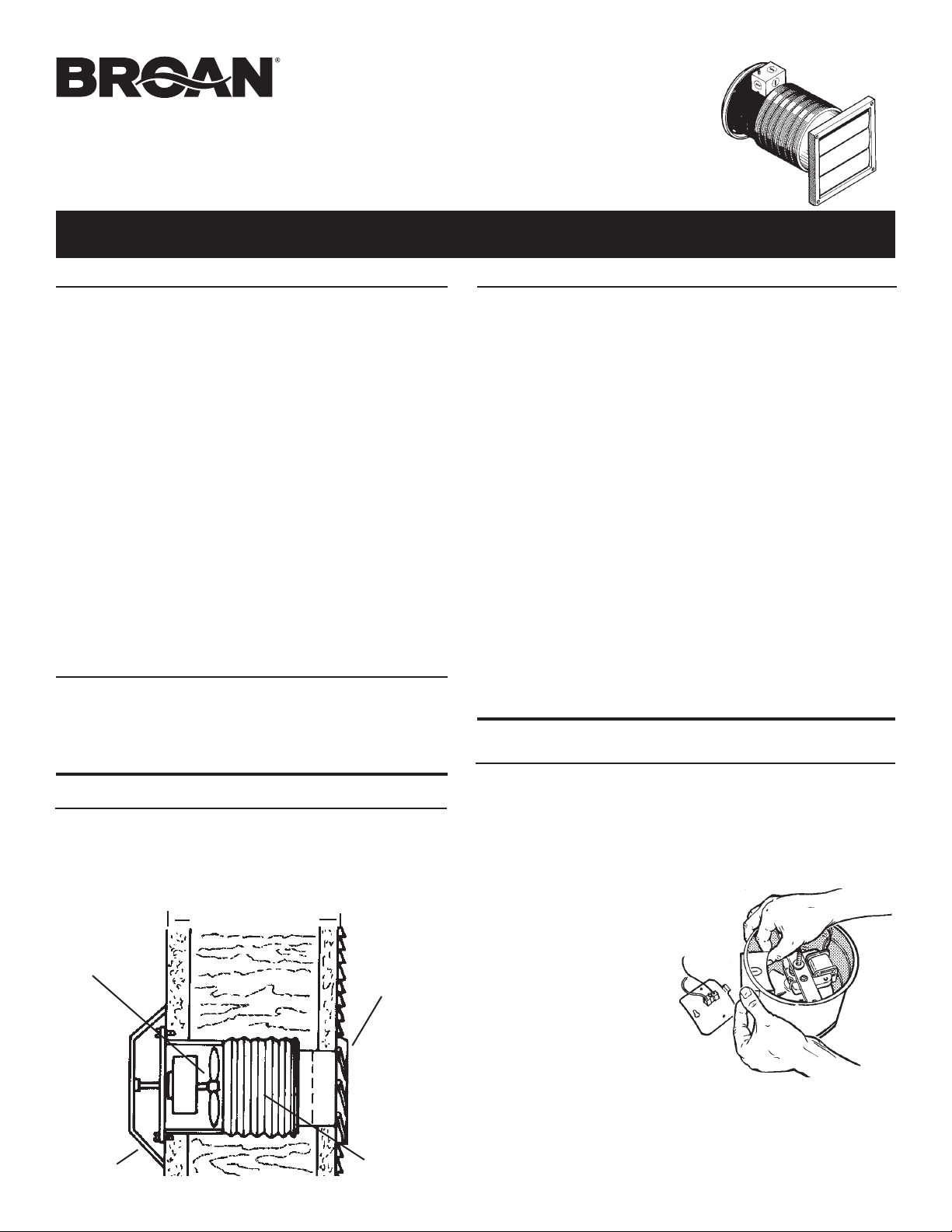
1 99110454 Grille
2 99260428 #6-32 Sheet Metal Nut (2 req.)*
3 99170245 #8B x 3/8 Sheet Metal Screw (3 req.)*
4 97005322 Motor Mounting Bracket 97005322
5 99080199 Motor (512M)
6 99020125 Blade
7 98004932 Wiring Box Cover
8 99150471 #10-32 x 1/2 Green Ground Screw*
9 98005329 Wiring Box
10 97011741 Housing
11 99270982 Receptacle
12 99610012 Adjustable Duct
13 97011740 Wall Cap
DESCRIPTION
NO.
PART
KEY
NO.
1. Spin grille onto its mounting screw until
the grille is tight against the wall.
2. Turn on the power and check for proper
operation of ventilator.
13
1
2
3
6
7
9
8
3
12
10
11
* Standard Hardware - May be purchased locally.
Always order replacement parts by “PART NO." - NOT by “KEY NO.”
5
4
WIRE THE VENTILATOR
WARNING:
SWITCH POWER OFF AT SERVICE PANEL AND LOCK SERVICE
PANEL BEFORE MAKING ELECTRICAL CONNECTIONS.
USE AND CARE
WARNING: SWITCH OFF POWER AT SERVICE PANEL AND LOCK
SERVICE PANEL BEFORE CLEANING OR SERVICING THIS VENTILATOR
.
TO CLEAN FAN ASSEMBLY:
Unplug motor from black receptacle. Remove the motor assembly by
loosening the mounting screws and rotating the motor assembly clockwise.
Gently vacuum motor assembly and inside of housing.
METAL AND ELECTRICAL PARTS SHOULD NEVER BE IMMERSED
IN WATER.
PERIODICALLY CHECK THE OUTER LOUVER FOR ACCUMULATED
DUST, LINT, ETC., WHICH MAY INTERFERE WITH PROPERLOUVER
CLOSURE.
WARNING: DO NOT SPRAY WATER INTO LOUVER-DAMAGE TO THE
FAN COULD OCCUR AND WATER COULD ENTER HOUSE.
MOTOR LUBRICATION
The motor is permanently lubricated. Do not oil or disassemble motor.
If the fan makes excessive noise or if there is unusual noise or smells of
smoke, disconnect power supply and contact customer service.
SERVICE PARTS
Model 512M
99043228D
MODELO 512M
VENTILADOR EMPOTRADO
ADVERTENCIA
PARA REDUCIR EL RIESGO DE INCENDIO, DESCARGA
ELECTRICA, O LESIONES PERSONALES, CUMPLA CON LOS
SIGUIENTES PUNTOS:
1. Solamente use esta unidad de la manera propuesta por el fabricante.
Si tiene alguna pregunta, póngase en contacto con el fabricante
en la dirección o teléfono anotados en la garantía.
2. Antes de limpiar o de poner en servicio la unidad, apague el inter-
ruptor en el panel de servicio, y asegure el panel de servicio para
evitar que se encienda accidentalmente. Cuando el dispositivo
para desconectar el servicio eléctrico no puede ser cerrado con
algún tipo de traba, sujete fuertemente al panel de servicio, una
etiqueta de advertencia prominente.
3. El trabajo de instalación y el alambrado eléctrico deben llevarse
a cabo por personal calificado de acuerdo con todos los códigos
y las normas aplicables, incluyendo los códigos y normas de
construcción contra incendios.
4. Se requiere una cantidad de aire suficiente para la combustión
y escape de gases por la chimenea del equipo de quemado
de combustible para prevenir la retrogresión de la llama. Siga
las especificaciones y estándares de seguridad para equipos
de calefacción del fabricante, tales como los publicados por la
Asociación nacional de protección contra incendios (NFPA por
sus siglas en inglés), y la Sociedad americana de ingenieros de
calefacción, refrigeración y aire acondicionado (ASHRAE), y los
códigos de las autoridades locales.
ADVERTENCIA
5. Cuando corte o taladre en una pared o techo, no dañe los cables
eléctricos u otras instalaciones ocultas.
6. Los ventiladores con ductos siempre deben ventilar hacia el
exterior.
7. Para reducir el riesgo de incendio, use solamente ductos de metal.
8. Esta unidad debe conectarse a tierra.
PRECAUCION
1. Solamente para uso de ventilación general. No se use para extraer
materiales o vapores peligrosos o explosivos.
2. Para evitar daños al cojinete del motor y/o impulsores ruidosos o
desequilibrados, mantenga la fuente de potencia lejos de rocíos
de pared seca, de polvo de construcción, etc.
3. Lea la etiqueta de especificaciones del producto para más información
y requisitos.
4. Se aconseja llevar guantes y gafas de protección durante la instalación,
el mantenimiento o la limpieza del aparato para reducir el riesgo de
lesiones causadas por la presencia de metal delgado y/o de piezas
móviles en altura.
Si se utiliza este ventilador para ventilar un garaje :
A. Utilizarlo solamente en el garaje de una casa unifamiliar
B. Instalar en un circuito protegido por un GFCI (interruptor accionado
por pérdida de conexión a tierra)
C. Para contribuir a reducir los riesgos impuestos por altas concentraciones
de vapor de pintura, de cola, de disolventes y de combustibles, instalar
el ventilador al menos a 0,5 m (18 pulgadas) del suelo
D. NUNCA dejar en funcionamiento el motor de un coche en un garaje.
NUNCA usar un aparato de combustión en un garaje. El monóxido de
carbono podría alcanzar un nivel peligroso, incluso mortal. El uso de
este ventilador de garaje o la apertura de puertas y ventanas no per-
mitirán un suministro suficiente de aire fresco para eliminar el peligro.
E. Activar periódicamente cuando el medio ambiente es salino
F. Una limpieza con mayor frecuencia podría ser necesaria debido al
medio ambiente potencialmente sucio
VENTILADOR
PARRILLA
CASQUETE
DE PARED
DUCTO
AJUSTABLE
LEA Y CONSERVE ESTAS INSTRUCCIONES
PREPARACION DE LA INSTALACION
El ventilador puede instalarse en paredes exteriores hasta 25,4 cm
de espesor. No se usa el ducto ajustable en paredes de menos de
15,2 cm. Escoja una posición sin obstrucciones, tales como clavos,
cañerías o alambrado eléctrico.
El ventilador puede ser controlado mediante el uso de un interruptor
de pared o un control de velocidad (disponibles por separado)
INSTALACION DEL VENTILADOR
ADVERTENCIA: CUANDO CORTE O TALADRE EN LA PARED, NO
CORTE EL ALAMBRADO ELECTRICO YA EXISTENTE.
PRECAUCION: No monte el ventilador sobre una superficie de
cocinado.
PRECAUCION: Mida y marque el centro de la abertura de la pared en
las paredes interior y exterior antes de cortar la abertura.
1. Corte un 6-3/8" abertura del
diámetro en la pared exterior.
2. Si usted está utilizando el
conducto ajustable, corte un
6-3/8" abertura del diámetro
en la pared interior. Si no,
corte un 6-1/8" abertura del
diámetro en la pared interior.
3. Desconecte el motor, afloje el
tornillo y remueva la cubierta
de la caja de cabies eléctricos.
4. Lea la etiqueta de especifica-
ciones del producto para más
información y requisitos.
Nota: Para remover la caja de cables de una forma fácil, remueva el
ensamble del motor. Afloje los tornillos de montaje y gire el ensamble del
motor en dirección de las agujas del reloj.
5¼ a 10 plg.
13,3 cm a 25,4 cm

ADVERTENCIA: DESCONECTE LA CORRIENTE EN EL PANEL
DE SERVICIO Y BLOQUEE EL PANEL DE SERVICIO ANTES DE
HACER LAS CONEXIONES ELECTRICAS.
1. Sujete el cable de corriente a la caja de cables eléctricos y la caja
de interruptores usando el conector apropiado para el tipo de
cable que se use.
2. Haga las conexiones eléctricas. Conecte el cable negro con el
negro, el blanco con el blanco, y el verde o el cable descubierto
a la caja de cables eléctricos.
CONEXION DEL DUCTO
(Para paredes de 5 a 10 plg. solamente - incluyendo cubiertas de
las paredes interior y exterior)
1. Estire el ducto ajustable, deslícelo sobre la carcasa y sujételo
con cinta en sitio. (Puede que sea necesario acortar el extremo
del ducto flexible que no es cónico para que quede bien.)
INSTALACION DEL VENTILADOR EN PARED
1. Coloque el ventilador en la abertura de la pared. Vuelva a instalar
la caja de cables eléctricos y cúbrala. Conecte el motor al recep-
táculo de la cubierta de la caja de cables.
2. Sujete el ventilador a la pared interior con los tornillos apropiados.
1. Desde el exterior, deslice el ducto ajustable en el casquete de
pared y sujete con cinta la unión.
2. Comprima el exceso de ducto hacia adentro de la abertura
colocando el casquete de pared contra la pared exterior.
3. Sujete el casquete de pared a la pared exterior y selle los bordes.
CAJADE CABLES
ELÉCTRICOS
SUJECCION DEL CASQUETE DE PARED
(Solamente siga los pasos 1 y 2 si se está usando ducto ajustable)
SUJECCION DE LA PARRILLATENDIDO ELÉCTRICO DEL VENTILADOR
BLANCO
INTERRUPTOR
DE VOLQUETE
CABLE
DESCUBIERTO
NEGRO
USO Y CUIDADO
ADVERTENCIA: DESCONECTE LA CORRIENTE Y SUELTE EL
PANEL DE SERVICIO ANTES DE LIMPIAR O PONER EN SERVICIO
ESTE VENTILADOR.
PARA LIMPIAR EL ENSAMBLE DEL VENTILADOR:
Desconecte el motor del receptáculo negro. Remueva el ensamble
del motor aflojando los tornillos de montaje y girando el ensamble del
motor en dirección de las agujas del reloj.
Aspire suavemente el ensamble del ventilador y en el interior de la carcasa.
EL METAL Y LAS PIEZAS ELECTRICAS NO SE DEBEN SUMERGIR
EN AGUA EN NINGUN CASO.
DE TIEMPO EN TIEMPO EXAMINE LA REJILLA EXTERIOR Y LIMPIE
EL POLVO, LA PELUZA, ETC. QUE SE HAYA ACUMULADO Y QUE
PUEDE IMPEDIR CERRAR BIEN LA REJILLA.
LUBRICACION DEL MOTOR:
El motor est
á
lubricado permanentemente y nunca necesita lubricaci
ó
n.
Si el ventilador emite un ruido excesivo o si se observan sonidos
anormales o un olor a humo, desconectar la fuente de alimentación y
póngase en contacto con el servicio al cliente.
PIEZAS DE SERVICIO
Modelo 512M
1
2
3
4
6
7
9
8
3
12
10
11
13
5
NO.
NO.
DESCRIPCIÓN
1 99110454 Parrilla
2 99260428 Tuerca No. 6-32 (son necesarias 2)
3 99170245 #8B x 3/8 Tornillo (Son necesarias 3)
4 97005322 Ménsula del motor
5 99080199 Motor (512M)
6 99020125 Rotor de soplo
7 98004932 Cubierta de la caja de cables
8 99150471 #10-32 x 1/2 Tornillo verde de tierra
9 98005329 Caja de cables eléctricos
10 97011741 Carcasa
11 99270982 Receptáculo
12 99610012 Ducto ajustable
13 97011740 Casquete de pared
Siempre encargue piezas de reemplazo por "NO. PIEZA" y no por "NO. CÓDIGO."
CÓDIGO PIEZA
1. Gire la parrilla en su tornillo de montaje hasta
que ésta esté apretada contra la pared.
2. Conecte la corriente y compruebe que el
ventilador funcione de manera apropiada.
GARANTÍA BROAN-NUTONE LIMITADA POR UN AÑO
Broan-NuTone garantiza al consumidor comprador original de sus productos que dichos productos carecerán de defectos
en materiales o en mano de obra por un período de un año a partir de la fecha original de compra. NO EXISTEN OTRAS
GARANTÍAS, EXPRESAS O IMPLÍCITAS, INCLUYENDO, PERO NO LIMITADAS A, GARANTÍAS IMPLÍCITAS DE COMERCIAL-
IZACIÓN O APTITUD PARA UN PROPÓSITO PARTICULAR.
Durante el período de un año, y a su propio criterio, Broan-NuTone reparará o reemplazará, sin costo alguno cualquier
producto o pieza que se encuentre defectuosa bajo condiciones normales de servicio y uso.
ESTA GARANTÍA NO SE APLICA A TUBOS Y ARRANCADORES DE LÁMPARAS FLUORESCENTES. Esta garantía no cubre (a)
mantenimiento y servicio normales o (b) cualquier producto o piezas que hayan sido utilizadas de forma errónea, negligente,
que hayan causado un accidente, o que hayan sido mantenidas o reparadas inapropiadamente(por otras compañías que
no sea Broan-NuTone), instalación defectuosa, o instalación contraria a las instrucciones de instalación recomendadas.
La duración de cualquier garantía implícita se limita a un período de un año como se especifica en la garantía expresa. Algunos
estados no permiten limitaciones en cuanto al tiempo de expiración de una garantía implícita, por lo que la limitacíon antes
mencionada puede no aplicarse a usted.
LA OBLIGACIÓN DE BROAN-NUTONE DE REPARAR O REEMPLAZAR, SIGUIENDO EL CRITERIO DE BROAN-NUTONE,
DEBERÁ SER EL ÚNICO Y EXCLUSIVO RECURSO LEGAL DEL COMPRADOR BAJO ESTA GARANTÍA. BROAN-NUTONE
NO SERÁ RESPONSABLE POR DAÑOS ACCIDENTALES, CONSIGUIENTES, O POR DAÑOS ESPECIALES SURGIDOS O EN
CONEXIÓN CON EL USO O EL RENDIMIENTO DEL PRODUCTO. Algunos estados no permiten la exclusión o limitación de
daños accidentales o consiguientes, por lo que la limitación antes mencionada puede no aplicarse a usted. Esta garantía le
proporciona derechos legales específicos, y usted puede también tener otros derechos, los cuales varían de estado a estado.
Esta garantía reemplaza todas las garantías anteriores. Para calificar en el servicio de garantía, usted debe (a) notificar a
Broan-NuTone al domicilio o al número de telefono que se menciona abajo, (b) dar el número del modelo y la identificación
de la pieza y (c) describir la naturaleza de cualquier defecto en el producto o pieza. En el momento de solicitar servicio
cubierto por la garantía, usted debe presentar evidencia de la fecha original de compra.
Broan-NuTone LLC Hartford, Wisconsin www.broan-nutone.com 800-558-1711
SUJÉTELO AQUÍ
SUJÉTELO
AQUÍ
CABLE DE ENERGíA
ELÉCTRICA DE 120/127 VCA
99043228D
