Package Contents:
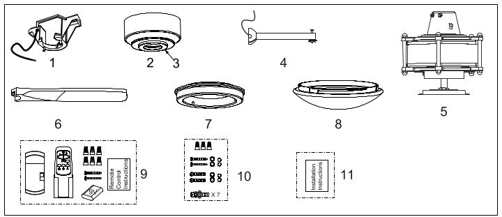
Unpack your fan and check the contents. You should have the following items.
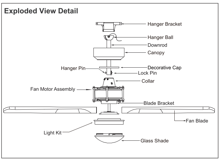
1.) Hanger Bracket
2.) Canopy
3.) Decorative Cap (Remove the Preassembled Decorative Cap from the Canopy Before Installation.)
4.) Downrod Set (Included Hanger Ball. 6” Downrod. Hanger Pin & Lock Pin)
5.) Fan Motor Assembly
6.) Fan Blades (3PCS)
7.) Light Kit
8.) Glass Shade
9.) Remote Control Set (Includes Receiver & Transmitter & Wire Connectors & Battery & Screws & Remote Control Instructions)
10.) Assembly Kit
11.) Installation Instructions
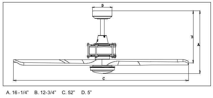
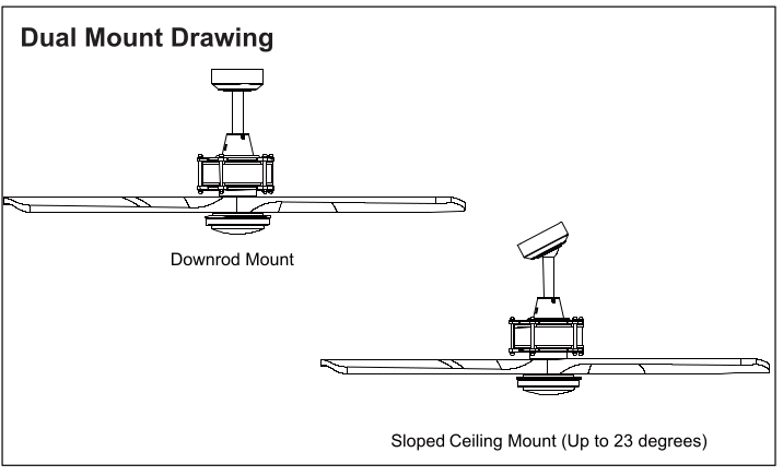
Dimension Reference (Installed with 6” Downrod):
Safety Instructions
READ ALL SAFETY INFORMATION AND INSTALLATION INSTRUCTIONS BEFORE YOU BEGIN TO INSTALL THE FAN AND SAVE INSTRUCTIONS.
+ All set screws of the fan must be checked and retightened where necessary before installation.
+ To reduce the risk of personal injury. do not bend the blade brackets when installing the brackets. balancing the blades or cleaning the fan. Do not insert foreign objects between rotating fan blades.
+ Before changing the fan direction. turn off the fan and wait for the fan blades to stop completely.
+ The safeguards provided by these safety instructions and by the separate installation instructions are not meant to cover all possible conditions and situations that may occur. It must be understood that common sense. caution and care are factors which can not be built into this product.
These factors must be supplied by the person(s) installing. caring for and operating the fan.
WARNING
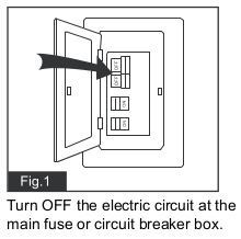
+ TO AVOID RISK OF ELECTRIC SHOCK. BE SURE TO SHUT OFF POWER AT THE MAIN FUSE OR CIRCUIT BREAKER BOX BEFORE INSTALLING OR SERVICING THIS FIXTURE. TURNING OFF THE ELECTRICAL POWER BY USING THE LIGHT SWITCH IS NOT SUFFICIENT TO PREVENT ELECTRICAL SHOCK.
+ TO REDUCE THE RISK OF INJURY. INSTALL THE FAN SO THAT THE BLADES ARE AT LEAST 7 FEET (2.1 METERS) ABOVE THE FLOOR AND AT LEAST 18 INCHES. (0.5 METERS) FROM THE TIP OF THE BLADES TO THE WALL.
+ TO REDUCE THE RISK OF FIRE. ELECTRIC SHOCK. OR PERSONAL INJURY. MOUNT TO OUTLET BOX MARKED "ACCEPTABLE FOR FAN SUPPORT" AND USE MOUNTING SCREWS PROVIDED WITH THE OUTLET BOX.
+ THE INSTALLATION HAS TO BE INACCORDANCE WITH THE NATIONAL ELECTRICAL CODE. ANSI/NFPA 70-1999 AND LOCAL CODES. IF YOU ARE UNFAMILIAR WITH THE. METHODS OF INSTALLING ELECTRICAL WIRING. SEEK THE SERVICES OF A QUALIFIED LICENSED ELECTRICIAN.
+ ETL LISTED FOR DAMP LOCATIONS; FOR USE IN COVERED PORCHES. ATIOS OR SUNROOMS WHERE RAIN OR WATER WILL NOT REACH THE CEILING FAN.
INSTALLATION INSTRUCTIONS
IMPORTANT:
+ BEFORE YOU BEGIN INSTALLATION. CAREFULLY READ ALL INFORMATION PROVIDED IN THE SAFETY INSTRUCTIONS AND INSTALLATION INSTRUCTIONS. IF IN DOUBT. CONSULT A QUALIFIED ELECTRICIAN.
+ SAVE ALL INSTRUCTIONS.
NOTE: The fan weight is 14.991bs (6.8 kgs). Be sure the outlet box you are using is securely attached to the building structure and can support the full weight of the fan. Failing to do so can result in serious injury.
Installation Steps :
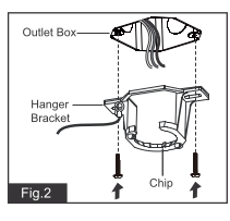
Tighten the hanger bracket to the outlet box with two mounting screws. (To reduce the tisk of fire. electric shock. or personal injury. mount to an outlet box marked "Acceptable for fan support” and use mounting screws provided with the outlet box)
Note: For sloped ceiling installation. make sure that the chip of the hanger bracket is toward the floor.
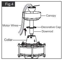
Thread the motor wires through the decorative cap (Making sure the smooth side of decorative cap is facing downward.). canopy and downrod.
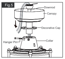
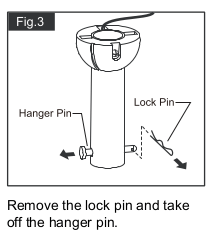
Loosen the collar screws out part way Insert the downrod into the collar. Slide hanger pin through holes of collar and downrod.
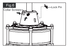
Tighten the two collar screws. Slide lock pin into hanger pin until itis locked into position
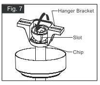
Hang the fan on hanger bracket. and make sure the slot of hanger ball is snapped into the chip of hanger bracket exactly.
Note: For sloped ceiling installation. make sure the slot of hanger ball and the chip of hanger bracket face down.
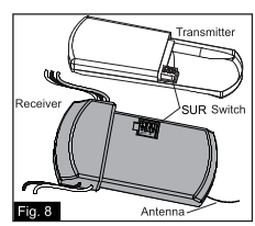
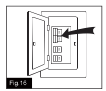
Both the transmitter and receiver have a 4-key Unit code on each SUR Switch (Fig.8) and by default. all keys are pre-set to the “of” positon. This means thatthe transmitter and receiver ae already paired together. However. if you have multiple fans and remote controls and want to avoid interference between them. you can "pair other transmitters and receivers together by adjusting the SUR switches. so the same numbered keys are in the "ON" position on both (Fig.8a).
Note: The coiling fan may work abnormally if there is interference from other remote controls.
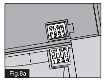
Code example:
1.ON
2- OFF
3-ON
4-OFF on both SUR Switches.
Note: if you have two ceiling fans with 2 romote control units. set 2 different codes for each set of transmitter / receiver.
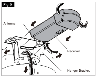
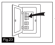
Move ground wires (a). outlet box wires (b). and motor wires (c) away from the center of the hanger bracket. Then slide receiver through hanger bracket as shown. Antenna end fist. unti its centered. Finally. cut motor wires (c) to length needed for connections.
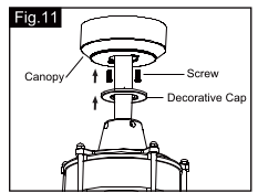
Secure the canopy to hanger bracket with serews. Attach the decorative cap to the canopy and rotate the decorative cap
Clockwise untl it locks in place.
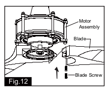
Align the holes on one of the blades with the holes on the bottom of fan motor assembly. then loosely attach the blade using the screws provided. Repeat this process for other blades. Once three blades are in position and connected with blade screws firmly tighten all screws.
Install fan light
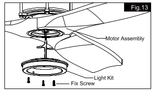
Remove three fix screws from bottom of motor assembly first. Then connect the white (neutral) wre from the light kit to white (neutral) wire from connect plate of light kit with a wire connector. connect the black (hot) wire from ight kit to biue (hot) wire from connect plate of ight kt with a wire connector. Carefully put the wires into the botiom of motor assembly. then attach the ight Kit onto the bottom of motor assembly with previous three fix screws.
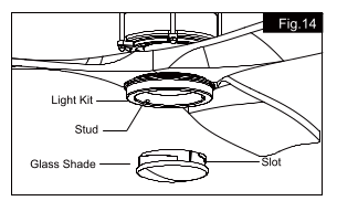
Attach the glass shade to the light kit by aligning studs and slots. and turn it clockwise until it is locked in place.
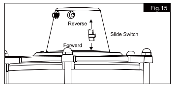
The slide switch on motor assembly sets direction of fan rotation.
Select the desired direction of fan rotation. Push the slide switch down for "Forward and up for "Reverse".
Note: Wait or fan to stop before revesing the direction of blade rotation.
Tum ON the electric cicuit at the main use or circuit breaker box.
Install the battery (9V. included) into the transmitter.
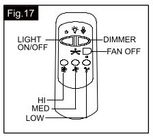
+ Press "HI" button to turn on the fan at high speed.
+ Press "MED" button to tum the fan in medium speed.
+ Press "LOW" button to turn the fan in low speed.
+ Press "FAN OFF" bution to turn off the fan.
+ Press “LIGHT ON/OFF” button to tum on or turnoff the light.
+ Press and hold the "DIMMER" button to dim or brighten lights to the desired level and. release. and the brightness level willbe memorized. Turn on the light again. then fan light wil be restored tothe brightness-level af which it was dimmed last time.
Note:
1. This remote controller has a memory function setting. The fan will operate at the same speed and the fan light will stay at the same brightness Jevol as the last time the power supply was tumed off.
2. Compatible Wall Switch: Menards SKU 363-5815.
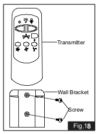
Install the transmitter wall bracket on the walll with two screws and place transmitter init carefully.
Install Without Remote Controller
Note: Remote controller can not be used along with a solid-state speed control at the same time.
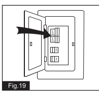
Turn OFF the electric circuit at the main fuse or circuit breaker box. (See Fig.19)
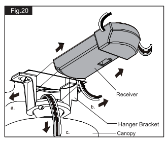
Unscrew the canopy. Remove the wire connectors from the fan to ceiling wire connection. The receiver should be removed from the hanger bracket. (See Fig. 20)
Turn ON the electric circuit at the main fuse or circuit breaker box.
Troubleshooting Guide
If fan does not start:
1. Check main and branch circuit fuses or circuit breakers.
2. Make sure forwardireverse switch is firmly in bottom or top position. Fan will not operate when switch is in the middle.
3. Make sure that the wall control is turned "ON".
4. Check line wire connections to fan and switch wire connections in switch housing.
CAUTION: Make sure main power is turned off.
If fan sounds noisy:
1. Make sure all screws in motor housing are snug. (not over tightened)
2. Make sure the screws which attach the fan blade bracket to the motor are tight.
3. Make sure wire connectors in switch housing are not rattling against each other or against the interior wall of the switch housing
CAUTION: Make sure main power is turned off before accessing switch housing.
4. Ifusing an optional ceiling fan light kit. make sure the screws securing the glassware are finger tight. Make sure light bulb is tight in socket and not touching glass shade(s). If vibration persists from glass. remove glass and install a 1/4 in. wide rubber band on glass neck to act as an insulator. Replace glass and tighten screws against rubber band.
5. Some fan motors are sensitive to signals from Solid State variable speed controls. DO NOT USE a Solid State variable speed control
6. Allow "break-in" period of 24 hours. Most noises associated with a new fan will disappear after this period
If fan wobbles:
All blades are weighed and grouped by weight. Natural woods vary in density which could cause the fan to wobble even though all blades are weight-matched. The following procedures should eliminate most of the wobble. Check for wobble after each step.
1. Check that all blades are screwed firmly into blade brackets.
2. Check that all blade brackets are tightened securely to motor.
3. Make sure that canopy and hanger bracket are tightened securely to ceiling junction box and junction box is mounted firmly to ceiling joist.
4. Most wobble problems of fan are caused when blades are not in equal level. To check the blade levels. select a point on the ceiling above the tip of any blade. Measure the distance from the ceiling to the blade tip. to an accuracy of 1/8 inch. Rotate the blades until the next blade is in the measuring position. Repeat measurement for each blade. If all blade levels are not equal. you can adjust blade levels by the following procedure. To adjust a blade tip down. insert a washer (not supplied) between the blade and blade bracket at the screw closest to the motor. To adjust a blade tip up. insert washer (not supplied) between the blade and blade bracket at the two screws farthest from the motor.
5. Interchanging two adjacent blades could redistribute the weight and possibly result in smoother operation
If light does not work:
1. Check blue wire from fan to make sure it is connected to hot wire from supply wire coming out of the ceiling
2. Check for loose or disconnected wires in fan switch housing.
3. Check for loose or disconnected wires in light kit
4. Check for faulty light bulbs.
CAUTION: Make sure main circ is turned off before entering switch housing.