
2 WNVR Series User’s Manual
Thank you for choosing Night Owl Security Products!
By purchasing a Night Owl product, you receive a one (1) year warranty covering
manufacturing defects in material and workmanship. Make the most of your
warranty by completing the registration form online. In addition to warranty
and technical support benefits, you will have access to our multitude of free
instructional “How to Videos”. You can also view our instructional videos by
clicking the “How to Videos” tab within your product’s page on our website.
Please see the warranty section of this manual for exclusions and additional details.
Not all features and capabilities are shared across all models so you may see
features which are not applicable. In addition you may see screen images that
do not exactly match those on your display. This manual was accurate at the time
it was completed. Due to our ongoing effort to constantly improve our products,
functions may have been added or changed.
Register at www.NightOwlSP.com!
Scan the QR code below to access our Quick Setup Guide that can
assist you in configuring your Night Owl Security system.
Night Owl highly recommends installing the most
current firmware version available for your system.
Verify your firmware version on the Device Info
screen of the System menu tab.
Quick Setup Guide

3Table of Contents
TABLE
OF CONTENTS

4 WNVR Series User’s Manual
Table of Contents
CHAPTER 1: FCC WARNINGS ..................................7
CHAPTER 2: SAFETY INSTRUCTIONS ............................9
CHAPTER 3: SPECIFICATIONS ................................11
3.1 System Requirements .............................12
3.2 Package Contents ................................12
3.2.1 NVR Diagram ..............................12
3.2.2 Camera Diagram ............................14
3.2.3 Mouse Diagram ............................14
CHAPTER 4: CAMERA INSTALLATION ...........................15
4.1 Power .......................................16
4.2 Mounting the Cameras .............................17
CHAPTER 5: NVR INSTALLATION ..............................19
5.1 Connecting your Wireless NVR .......................20
CHAPTER 6: GETTING STARTED ...............................23
6.1 Startup Wizard ..................................24
6.1.1 Camera Test ...............................25
6.1.2 Network Check .............................25
6.1.3 Firmware Check ............................27
6.1.4 Password Creation ..........................28
6.1.5 Date and Time Setup ........................30
6.1.6 Night Owl X ...............................31
6.1.7 Password Verification ........................32
6.1.8 Camera/Channel Settings .....................33
6.1.9 Camera Positioning ..........................33
6.1.10 Channel Configuration ........................ 34
6.1.11 Default View ..............................36
6.1.12 Helpful Links ..............................37

5Table of Contents
6.1.13 Wizard Complete ...........................37
6.2 Night Owl X Mobile App ............................38
6.3 Live View (Logins and Icons) .........................38
6.3.1 Live View (All Channels) ......................38
6.3.2 Right Click Menu ...........................39
6.3.3 Login/Forgot Password .......................40
6.3.4 Video Playback .............................41
CHAPTER 7: MENUS AND SETTINGS ...........................42
7.1 General Menu ...................................45
7.1.1 Display ..................................45
7.1.2 Network ..................................46
7.1.3 DDNS ...................................47
7.1.4 Video Alarm ...............................47
7.1.4 (a) Notification Schedule. . . . . . . . . . . . . . . . . . . . 48
7.1.4 (b) Area Setup ...........................49
7.2 Cameras Menu ..................................49
7.2.1 Status ...................................49
7.2.2 Add Camera ...............................50
7.2.2 (a) Edit ................................51
7.2.2 (b) Wireless Add ..........................52
7.2.2 (c) Advance .............................52
7.2.2 (d) Manual Edit ..........................53
7.2.2 (e) Repeater .............................54
7.2.3 On Screen Display ..........................54
7.2.3 (a) Image Settings ........................55
7.2.4 Video Quality ..............................56
7.2.5 Cam Firmware Upgrade .......................57
7.3 Record .......................................57
7.3.1 Schedule .................................57

6 WNVR Series User’s Manual
Night Owl’s NVRs are manufactured for quality and ease of use.
As such, our NVRs contain menus designed for advanced users
that should not be adjusted without having enhanced knowledge
regarding the menu. In most cases the default settings allow for
optimal functionality. The menus that should maintain the default
settings are indicated with this icon.
ADVANCED
DISCLAIMER: The exact components of your system, images and quantities may
vary depending on your model number. While these may vary, this Manual will
address the setup and initial configuration of your NVR and cameras.
7.3.2 Export Recordings ..........................58
7.4 Hard Drive .....................................59
7.5 System .......................................60
7.5.1 System Settings ............................60
7.5.1 (a) Advance .............................61
7.5.1 (b) Setup ...............................61
7.5.2 NVR WiFi Settings ..........................62
7.5.3 User Management ..........................62
7.5.4 Device Info ...............................63
7.5.5 Log .....................................64
7.5.6 Camera Speed .............................64
7.6 Maintain .......................................65
7.6.1 Sys Maintain ..............................65
7.6.2 Firmware Update ...........................65
7.6.3 Firmware Default ...........................66
CHAPTER 8 GLOSSARY .....................................67
CHAPTER 9: WARRANTY .....................................69
CHAPTER 10: TROUBLESHOOTING ..............................72
CHAPTER 11: USER INFORMATION .............................75
CUSTOMER SUPPORT .......................Back Cover

7Chapter 1: FCC Warnings
CHAPTER 1
FCC WARNINGS

8 WNVR Series User’s Manual
Chapter 1: FCC Warnings
FCC Radiation Norm
FCC
This device complies with Part 15 of the FCC Rules. Operation is subject to the
following two conditions: (1) this device may not cause harmful interference and
(2) this device must accept any interference received, including interference that
may cause undesired operation.
FCC Compliance Statement
These limits are designed to provide reasonable protection against frequency
interference in residential installation. This equipment generates, uses and can
radiate radio frequency energy and if not installed or used in accordance with the
instructions, may cause harmful interference to radio communication. However,
there is no guarantee that interference will not occur in television reception, which
can be determined by turning the equipment off and on. The user is encouraged
to try and correct the interference by one or more of the following measures:
• Reorient or relocate the receiving antenna.
• Increase the separation between the equipment and the receiver.
• Connect the equipment into an outlet on a circuit different from that to which
the receiver is connected.
• Consult the dealer or an experienced radio/TV technician for help.
CAUTION
The Federal Communications Commission warns the user that changes or
modifications to the unit not expressly approved by the part responsible for
compliance could void the user’s authority to operate the equipment.

9Chapter 2: Safety Instructions
CHAPTER 2
SAFETY
INSTRUCTIONS

10 WNVR Series User’s Manual
Use the provided power adapter.
Do not use this product with a power
source that applies more than the
specified voltage.
Never insert metal into the NVR case
or its openings. Inserting metal into the
NVR case may cause electric shock.
Do not operate in wet or dusty areas.
Avoid placing the NVR in areas such
as a damp basement or dusty attic.
Do not expose the NVR to rain or use
near water. If the NVR accidentally
gets wet, unplug it and contact
technical support immediately.
Keep product surfaces clean and dry.
To clean the outside case of the NVR,
use a lightly dampened cloth. Do not
use cleaning solutions or solvents.
Do not install near any heat sources.
Do not install the NVR near any heat
sources such as stoves, heat registers,
radiators or electronics (including
amplifiers) that produce heat.
Unplug the NVR when moving it.
Make sure that the NVR is unplugged
before you move it. When moving this
device, be sure to handle it with care.
Make sure there is good air circulation
around the NVR.
This NVR uses an internal hard drive,
which generates heat during operation
for video storage. Do not block vents
on the NVR, as these vents reduce
the generated heat while the system
is running. Place this product in well-
ventilated area.
Do not attempt to remove the top
cover. If you observe any abnormal
operation, unplug the NVR immediately
and contact technical support. Do not
attempt to open the NVR to diagnose
the cause of the problem.
Handle the NVR carefully.
If you drop the NVR on any hard
surface, it may damage the device.
If the NVR doesn’t work properly
due to physical damage, contact an
authorized dealer for repair.
It is recommended to use your NVR
with an uninterruptible power supply
(UPS). Connecting your NVR and
cameras to a UPS allows continuous
operation even during power outages.
The run-time duration will depend on
the rating of the UPS used.
Chapter 2: Safety Instructions
You may be subjected to severe electrical shock
if you remove the cover of the NVR.

11Chapter 3: Specifications
CHAPTER 3
SPECIFICATIONS
12 WNVR Series User’s Manual
Chapter 3: Specifications
3.1 System Requirements
Please be sure that your PC/MAC
®
complies with the following specifications:
• PC Operating System: Windows
®
7, Windows
®
8/8.1 and Windows
®
10
• PC Browser: IE
®
8 and above, Edge
®
, Google Chrome™ and Firefox
®
• MAC Operating System: MAC OS X
®
10.7 and above
• MAC Browser: Safari
®
7.1 and above
Please be sure that your mobile device complies with the following specifications:
• Android™: 4.0 and above
• iOS
®
: 7.1 and above
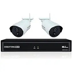
3.2 Package Contents
• 1080p HD NVR with pre-installed
1 TB Hard Drive
• 1080p Indoor/Outdoor Wireless
Infrared IP Cameras*
• Mounting Hardware and Screws*
• HDMI Cable
• 1 x RJ-45 Cable (Ethernet)
• Wi-Fi Extender Antenna*
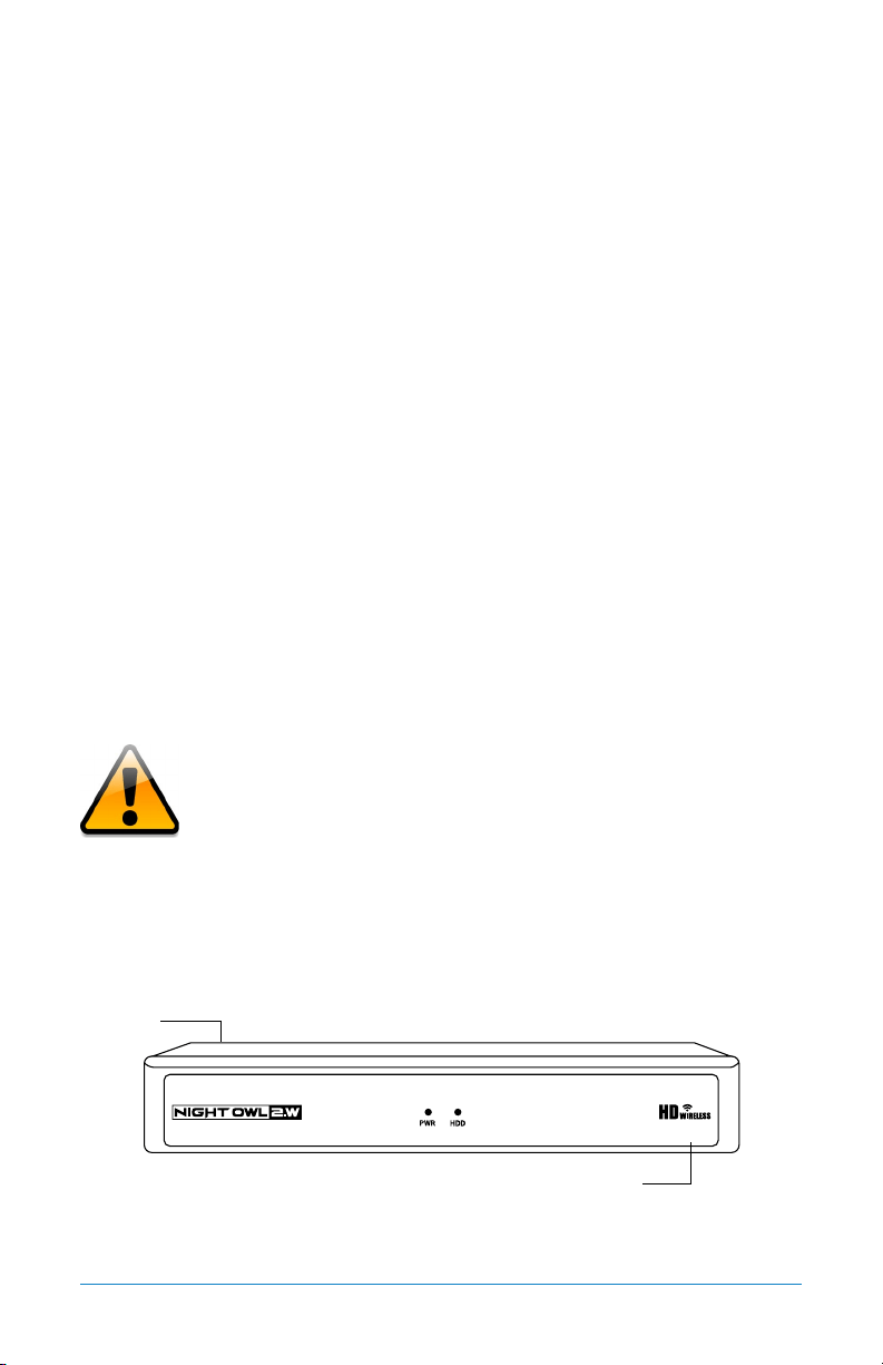
3.2.1 NVR Diagram
FRONT VIEW
Cameras, additional cables, power adapters and
splitters only included in certain security kits. Check
the product packaging for detailed kit contents.
• 1 x USB Mouse
• Camera Antennas (1 per Camera)
• 9 ft. Camera Power Adapters*
• 1 x NVR Power Adapter
• 2 x NVR Antennas
• 1 x Support Material Packet
• 3 x Night Owl Security Stickers
QR Code
Once you have downloaded Night Owl X and connected your
NVR to your router, you can network your NVR by scanning
the QR code which is located on the top of the NVR.
WNVR-20B-81
Model #
13Chapter 3: Specifications
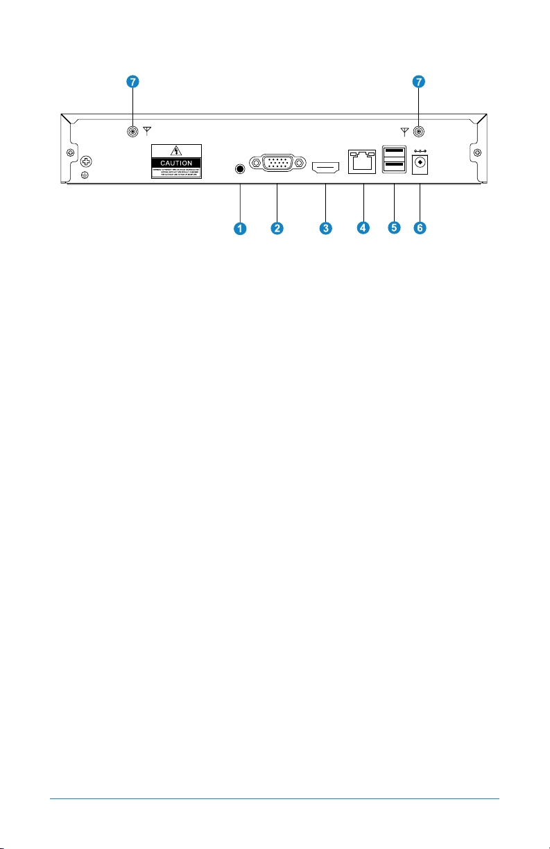
REAR VIEW
Images used are for reference only. Your product may vary slightly.
1. Audio Output – allows for the connection of an amplified speaker.
2. VGA Output – VGA output allows for a video connection. If the TV/Monitor
does not have an HDMI input but does have a VGA input, connect the VGA
cable from the VGA output port on the NVR to the VGA input port on your
TV/Monitor. (VGA cable not included)
3. HDMI Output – HDMI output allows for a video connection. If the TV/Monitor
has an HDMI input, connect the HDMI cable from the HDMI output port on
the NVR to the HDMI input port on your TV/Monitor.
4. RJ-45 (Ethernet) Port – The RJ-45 port will be used to connect the Wireless
NVR to your modem/router for remote viewing. Please note that your Wireless
NVR comes with built-in Wi-Fi for the cameras to transmit to the NVR. However,
you will need to manually connect the NVR to your modem/router to remotely
view on a smart device or PC/Mac
®
.
5. USB Ports – USB ports allow for the connection of a USB mouse and/or a
USB flash drive. You will connect the included USB mouse to assist you in
navigating the NVR’s menu interface. You will connect a USB flash drive to
download video files from the NVR for long term storage or sharing.
6. Power Input – Power input is used to connect the included 12V DC power supply.
7. NVR Antenna Mount – for installation of two included NVR antennas.
Audio
Output
HDMI
Output
VGA
Output
RJ-45
(Ethernet)
Port
USB
Ports
Power
Input
NVR Antenna
Mount
NVR Antenna
Mount
AUDIO
OUTPUTGROUND
VGA
HDMI
LAN
USB
POWER
12V
The maximum number of cameras you can connect to your
Wireless NVR will be determined by the number of channels.
14 WNVR Series User’s Manual
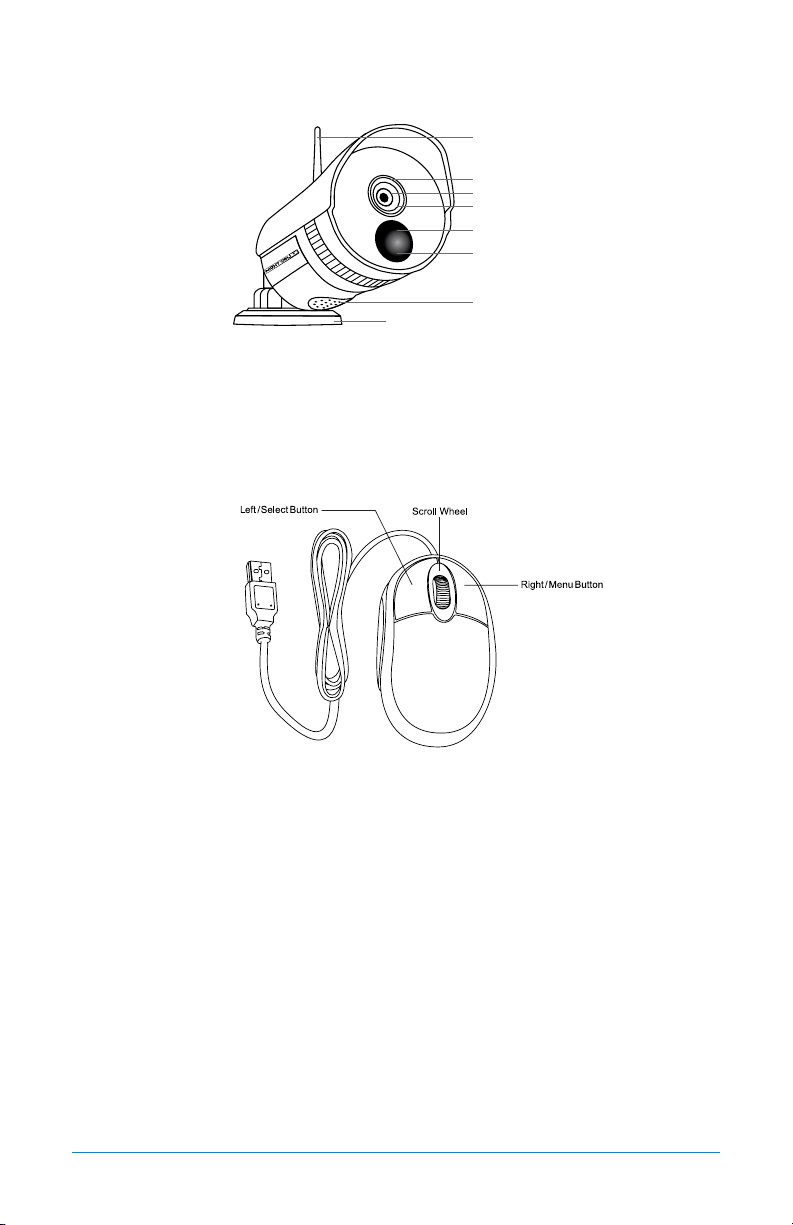
3.2.2 Camera Diagram
CAMERA
NOTE: Connect all cameras locally before final placement to ensure that all
components function properly.
3.2.3 Mouse Diagram
MOUSE
Live Viewing:
Double-click the left button on any camera view in split-screen mode to bring it to
full screen display.
Double-click again to return to split-screen mode.
Right-click to show the control bar at the bottom of the screen.
Right-clicking again will hide the control bar.
In Setup:
Left-click to make a selection.
Right-click to cancel setup or return to previous screen.
To Enter Values:
Move the cursor to a blank field and click the mouse. A virtual keyboard will
appear which supports numbers, letters and symbols. The Shift function will
access symbols in addition to upper case letters.
Infrared PIR Sensor
2-Way Audio
IR Cut Filter
1080p Resolution
Wide Viewing Angle 100º
Night Vision up to 100 ft.
300 ft. Wireless Range
3-Axis Mounting Bracket
(Vandal-Proof Wire
Camera Protection)

15Chapter 4: Camera Installation
CHAPTER 4
CAMERA
INSTALLATION
16 WNVR Series User’s Manual
Chapter 4: Camera Installation
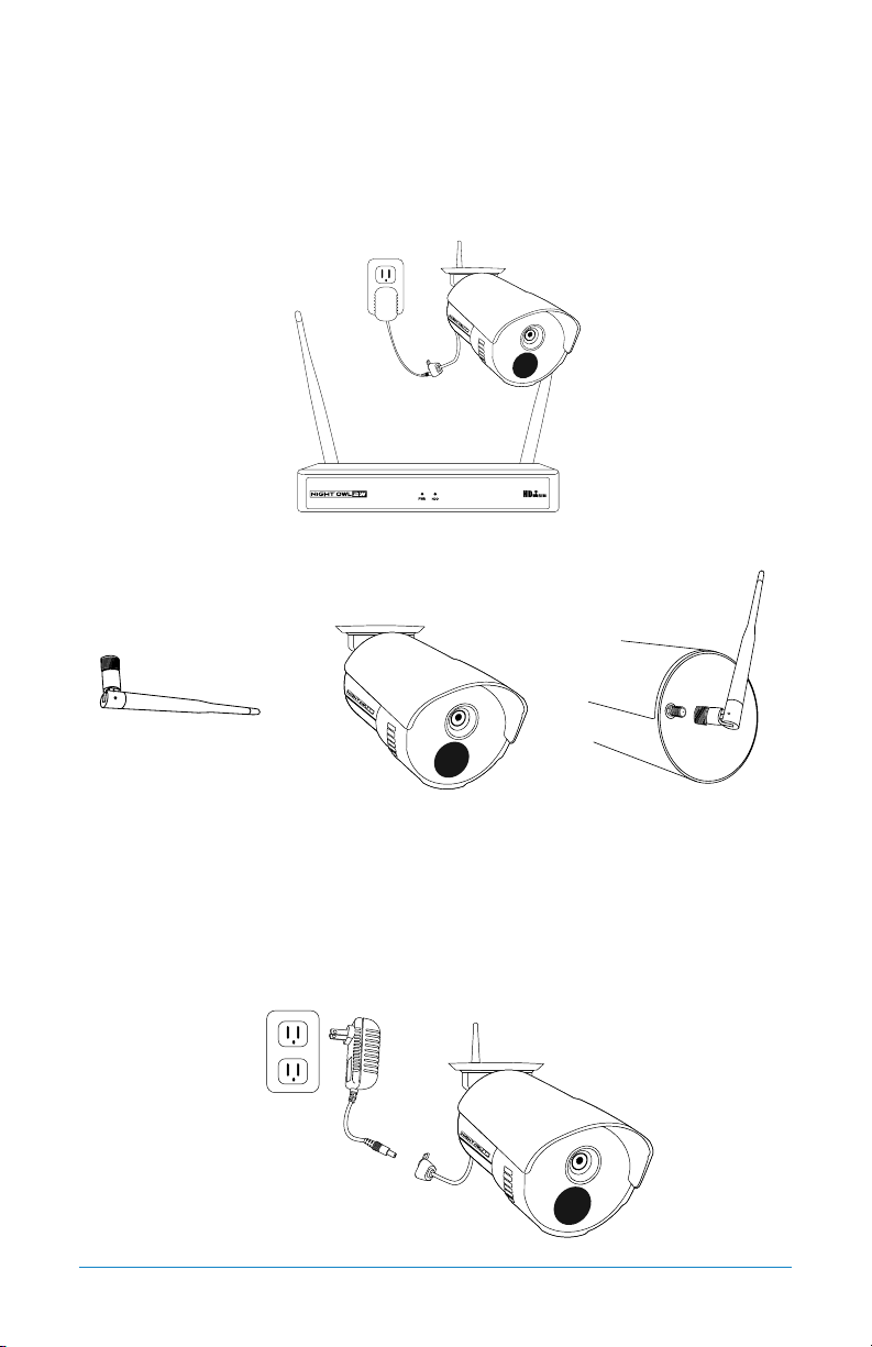
4.1 Power
NOTE: Connect all cameras locally before final placement to ensure that all
components function properly.
1. Locate the antenna included with each camera.
2. Fasten the antenna to the camera.
3. Locate the camera power adapter and connect it to a surge protector, UPS or
wall outlet.
4. Connect the camera power adapter to camera.
5. Repeat for each camera.
Camera(s)
Camera Antenna
(1 per camera)
17Chapter 4: Camera Installation
4.2 Mounting the Cameras
Camera distance from NVR.
Your wireless IP cameras will reach up
to 300 ft. wirelessly. Therefore, proper
placement of the wireless NVR in your
home will help ensure you achieve
maximum coverage.
Do not place near high voltage wires or
other sources of electrical interference.
Electrical interference will degrade the quality of the signal.
Place camera out of reach to avoid vandalism.
Avoid direct exposure to weather. Do not place the camera where rain or snow will
hit the lens directly nor should the camera be placed so that the sun or bright
light shines directly into the lens. Your camera is weatherproof, but it will not work
when submerged in water. Ensure that all power and video connections are not
directly exposed to water and are protected from the elements.
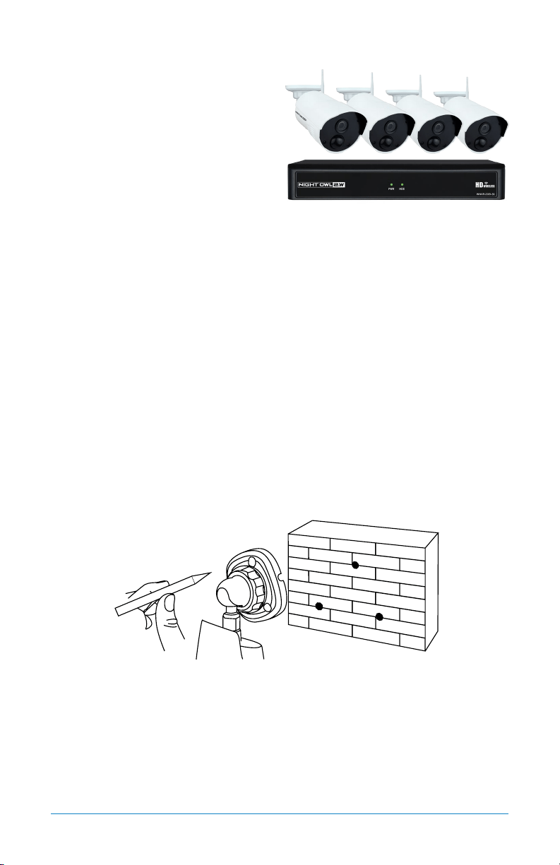
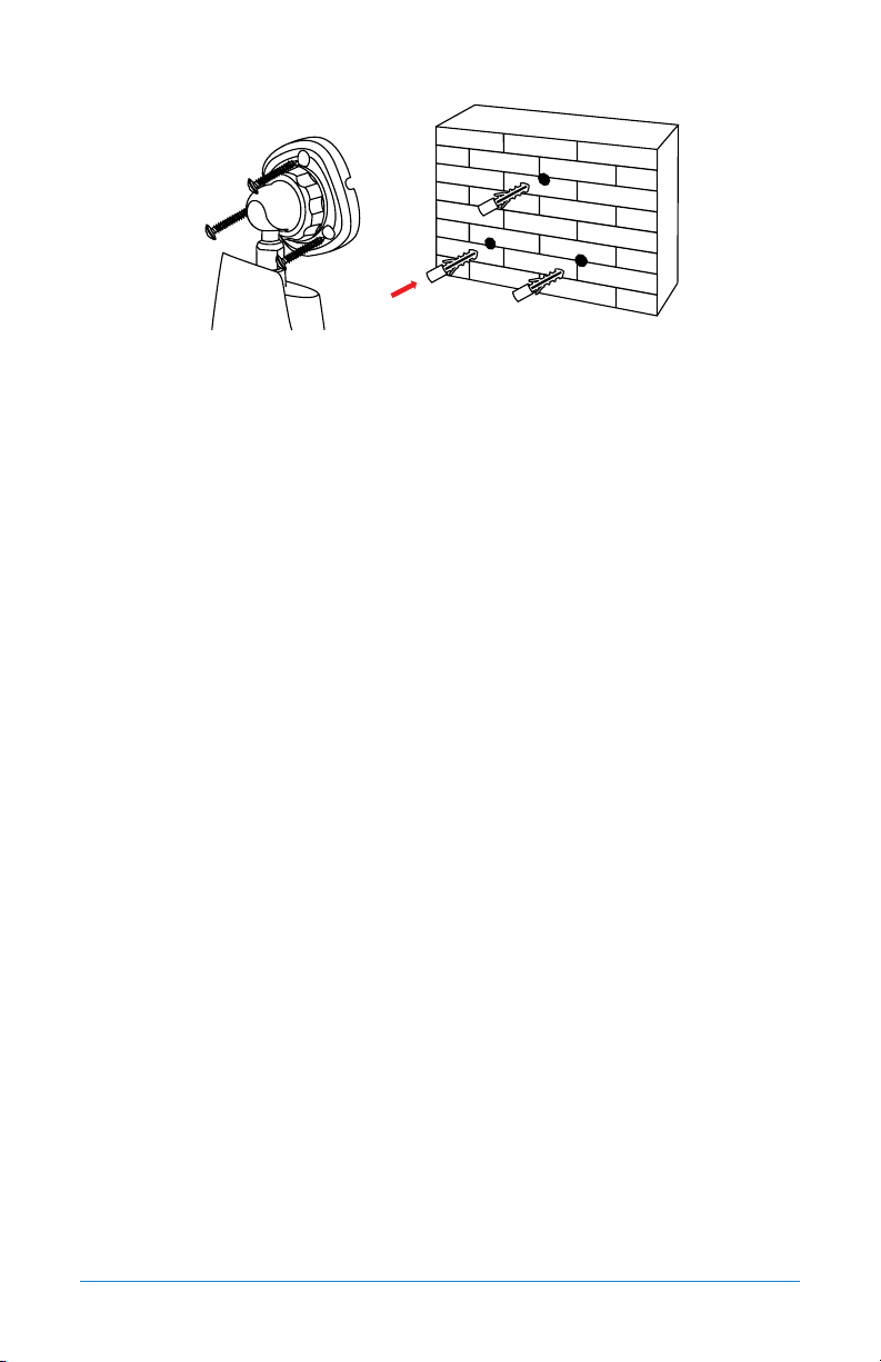
Mounting surface. The mounting surface must hold at least four times the
camera’s total weight.
1. Locate a camera and choose a location where you would like to mount
the camera.
2. Indicate screw positions by marking three holes on the surface where you plan
to mount the camera, using the holes in the camera base as a guide.
3. Using a drill bit slightly smaller than the included screw anchors, drill into the
mounting surface using the guide marks you placed in the previous step.
4. Insert the screw anchors.
5. Line up the camera base holes with the screw anchors. Holding the base in
place, insert screws and tighten until secure.
Connect all cameras locally before final placement
to ensure that all components function properly.
18 WNVR Series User’s Manual
6. Once the base is screwed in place, make sure that the camera is securely
mounted by placing gentle pressure on the mount.
7. Adjust the camera housing to point in the direction of the area you would like
to monitor.

19Chapter 5: NVR Installation
CHAPTER 5
NVR INSTALLATION
20 WNVR Series User’s Manual
Chapter 5: NVR Installation
5.1 Connecting Your Wireless NVR
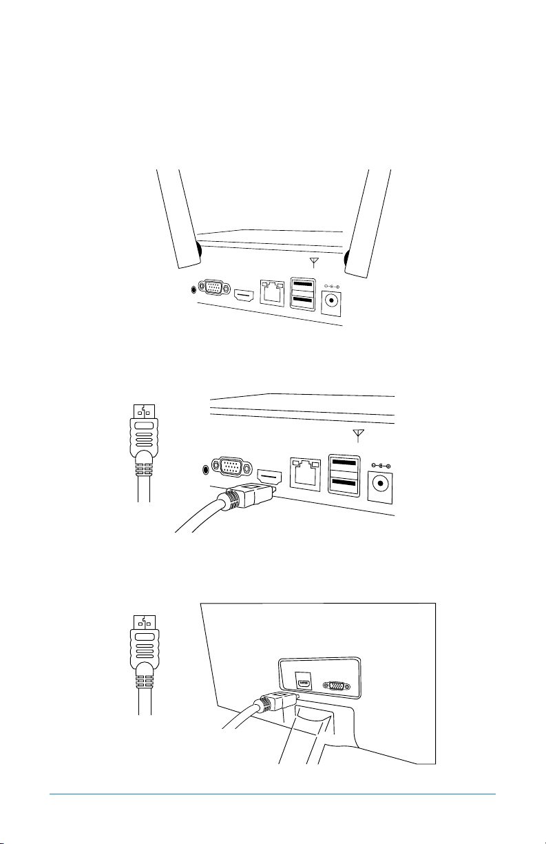
1. Connect the two included antennas to your wireless NVR. This will ensure you
achieve the maximum wireless range for transmission from your wireless cameras.
2. Plug one end of the included HDMI cable into the HDMI port on the back of
the Wireless NVR.
3. Plug the other end of the HDMI cable into the back of your TV or monitor.
HDMI
HDMI
You may also connect using VGA (not included)
21Chapter 5: NVR Installation
If your TV does not have an HDMI port, you will need
to purchase a VGA or a BNC-to-RCA video cable.
For a VGA connection, attach one end of the VGA
cable to the NVR VGA port and the other end to your TV
VGA port.
4. Select the appropriate video input channel on your TV or monitor to view
the NVR.
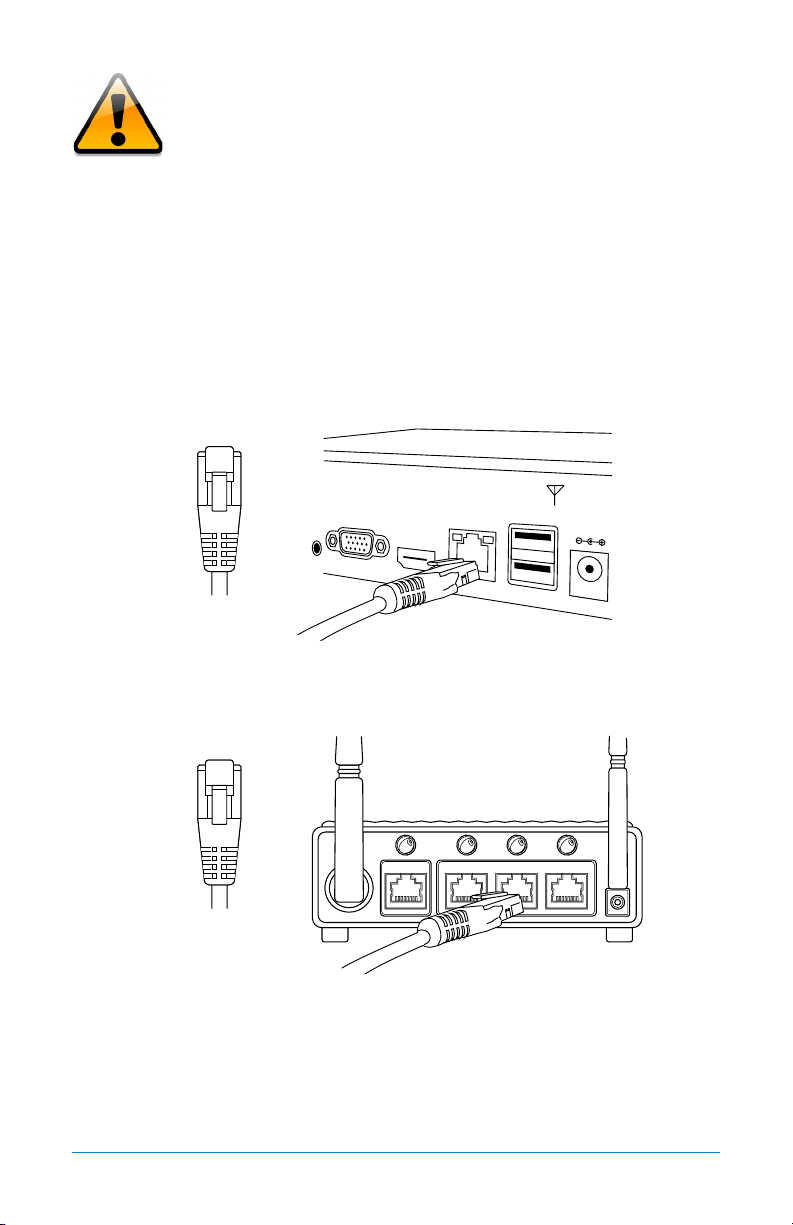
5. Plug one end of the included Ethernet cable into the LAN port on the back of
the Wireless NVR.
6. Plug the other end of the Ethernet cable into a port on the back of your router.
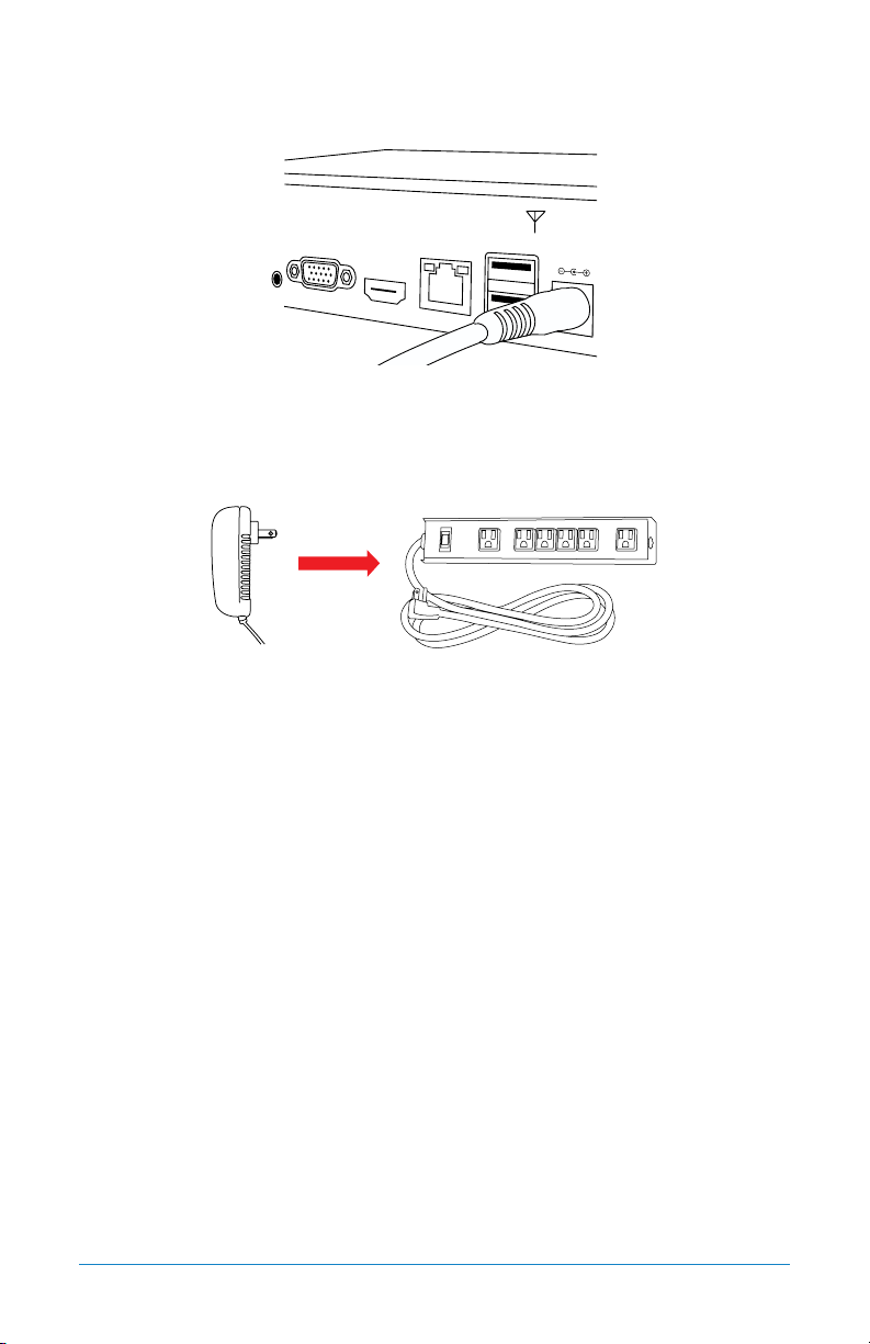
7. The Camera and NVR power adapters will be appropriately labeled. Ensure you
are using the correct power adapter when setting up your system.
ETHERNET
ETHERNET
Router not included
22 WNVR Series User’s Manual
8. Connect the Wireless NVR power adapter to the Power Input on the rear of the
Wireless NVR.
9. Plug the Wireless NVR power adapter into a surge protector or Uninterruptible
Power Supply (UPS). (surge protector and UPS not included)
You should see each camera appear on your TV/Monitor. You may now proceed to
install your Wireless NVR cameras in the desired location.

23Chapter 6: Getting Started
CHAPTER 6
GETTING STARTED
24 WNVR Series User’s Manual
Chapter 6: Getting Started
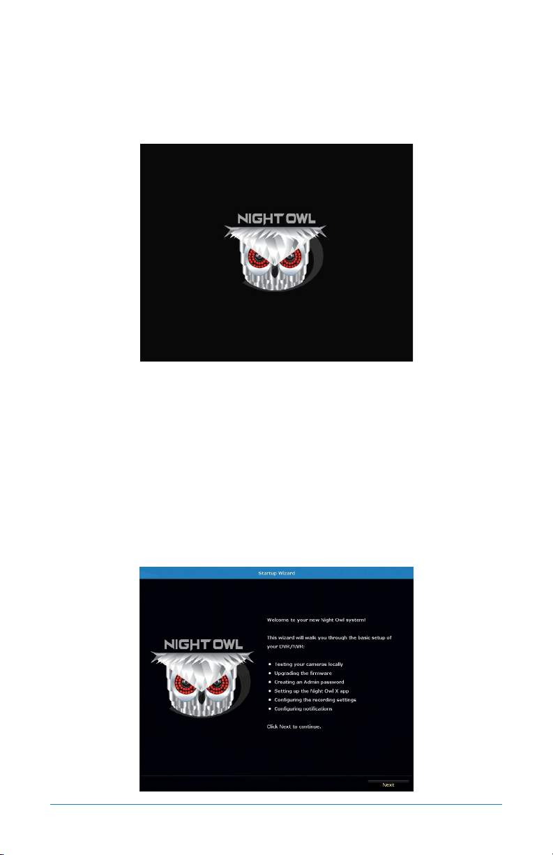
6.1 Startup Wizard
When your NVR is powered on it will display the Night Owl logo while initializing.
After initialization, you will be prompted to use the Startup Wizard. Follow the
on-screen instructions to:
• Complete the basic setup of your NVR.
• Test your cameras locally.
• Upgrade the firmware.
• Create an Admin password.
• Set up the Night Owl X App.
• Configure the recording settings.
• Configure notifications.
25Chapter 6: Getting Started
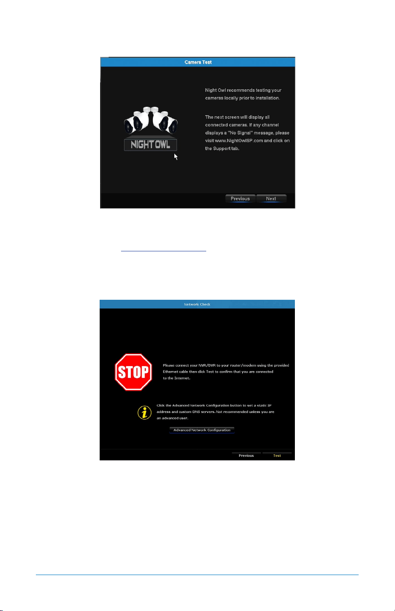
6.1.1 Camera Test
The Camera Test screen of the Startup Wizard serves as a reminder to test the
camera connections to the NVR. If a connected camera displays a “No Signal”
message, please visit www.NightOwlSP.com and click on the Support tab.
NOTE: It may take up to 3 minutes for your wireless cameras to appear on screen.
6.1.2 Network Check
The Network Check screen of the Startup Wizard displays instructions on how to
connect your NVR to the Internet. You will need the included Ethernet cable to
establish a connection. Though the cameras wirelessly connect to the NVR, the
NVR will not be able to wirelessly connect to your router/modem.
Once you have made the required connection using the Ethernet cable, you may
click Test within the Startup Wizard to confirm Internet connection.
26 WNVR Series User’s Manual
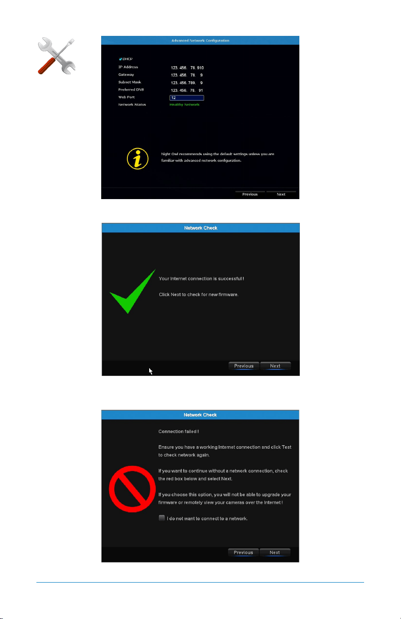
The Advanced Network Configuration tab is recommended only for advanced users.
Once the Internet connection has been established, the Startup Wizard will
display a successful connection screen.
If your NVR is not able to establish Internet connectivity, a connection failed screen
ADVANCED
27Chapter 6: Getting Started
will appear. Follow the instructions on this screen to re-test the network. If you
wish to proceed with the NVR setup without a network connection, you may do so by
clicking the box marked, “I do not want to connect to a network.”
NOTE: Without an Internet connection, you will not have easy access to firmware
updates or be able to remotely view your system on a PC/Mac
®
or smart device.
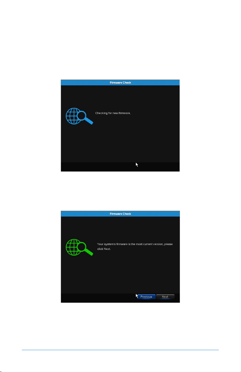
6.1.3 Firmware Check
The Firmware Check screen of the Startup Wizard will automatically check for
updated firmware for your NVR.
NOTE: If your NVR does not have a network connection, the firmware will not update.
When the firmware for your NVR is updated to the most current version, the
Startup Wizard will display the above screen.
28 WNVR Series User’s Manual
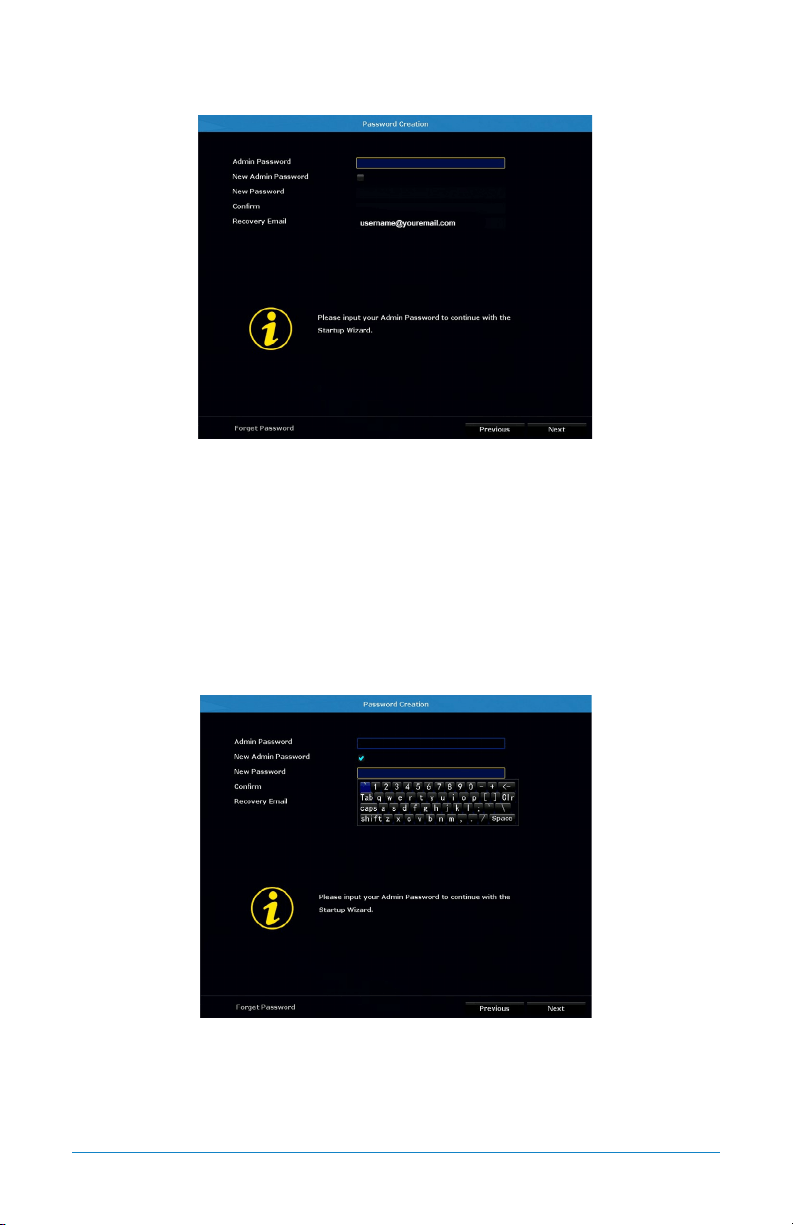
6.1.4 Password Creation
The Password Creation screen of the Startup Wizard requires you to create an Admin
password for your NVR system. Night Owl strongly suggests that you write down your
Admin password on page 7 of the Quick Setup Guide, as you will be required to log
in any time you want to configure or adjust your system settings.
This screen will also require that you set a recovery email address in the event
that your Admin password is forgotten.
NOTE: You will not be able to complete the Startup Wizard unless a recovery
email address is established.
Simply click on the text box to open the on-screen keyboard. Use this keyboard
to create your Admin password and to input your recovery email address.
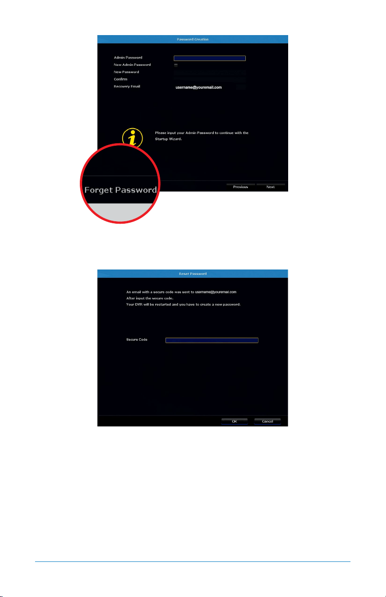
29Chapter 6: Getting Started
If you have forgotten your Admin password, simply click on the “Forget Password”
tab in the Startup Wizard.
A Secure Code will be sent to your recovery email address. Use the Secure Code
to restart your NVR and create a new password.
30 WNVR Series User’s Manual
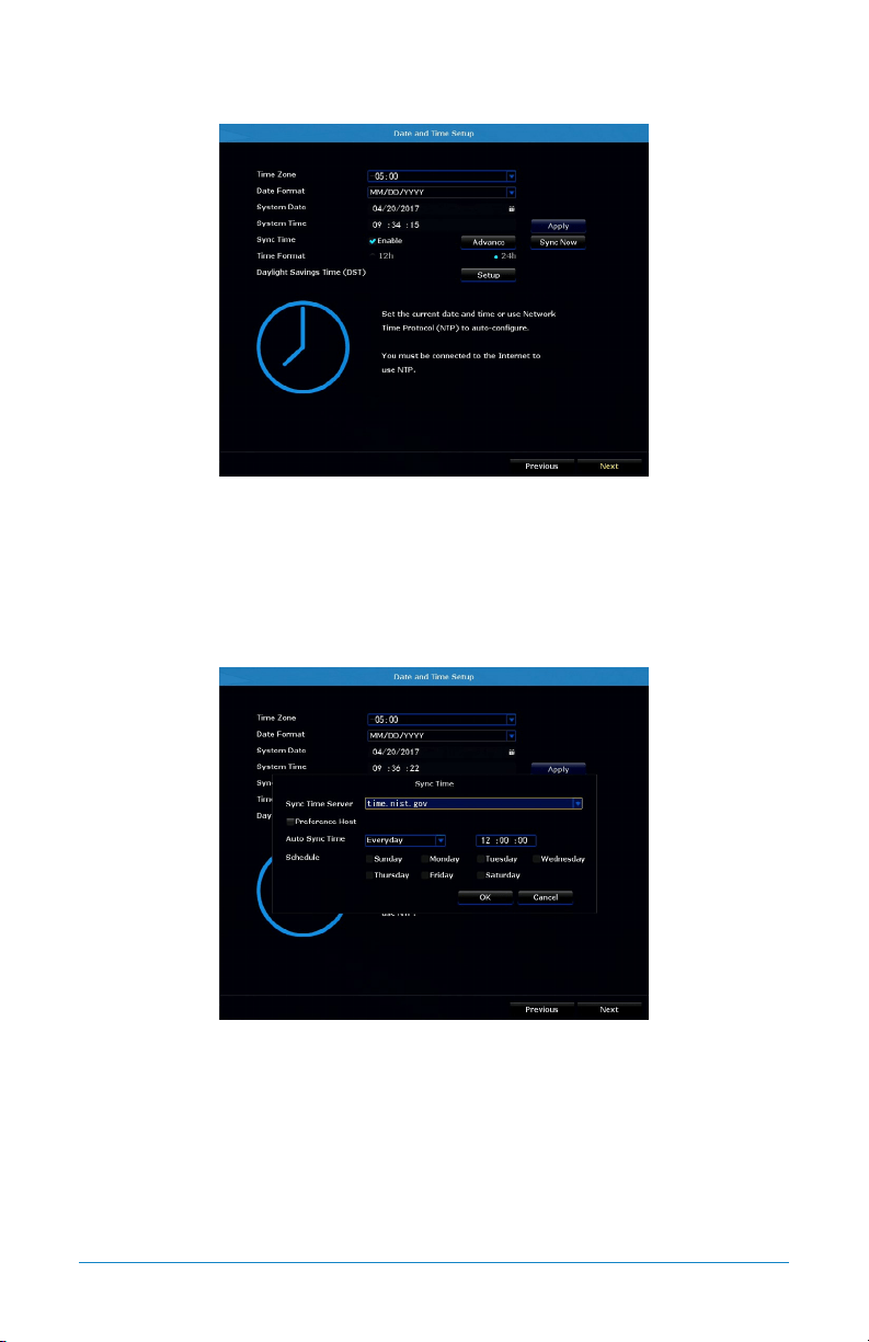
6.1.5 Date and Time Setup
The Date and Time Setup screen of the Startup Wizard will allow you to set the
current date and time. You may choose to use Network Time Protocol (NTP) to
auto-configure the current date and time. To use NTP, check the Enable box next
to Sync Time, then click Sync Now.
NOTE: Selecting Sync Now will temporarily stop recording while syncing NTP.
By clicking the Advance tab on the Sync Time line, you can edit the Sync Time
Server as well as schedule Auto Sync Time to prompt your NVR to automatically
sync NTP.
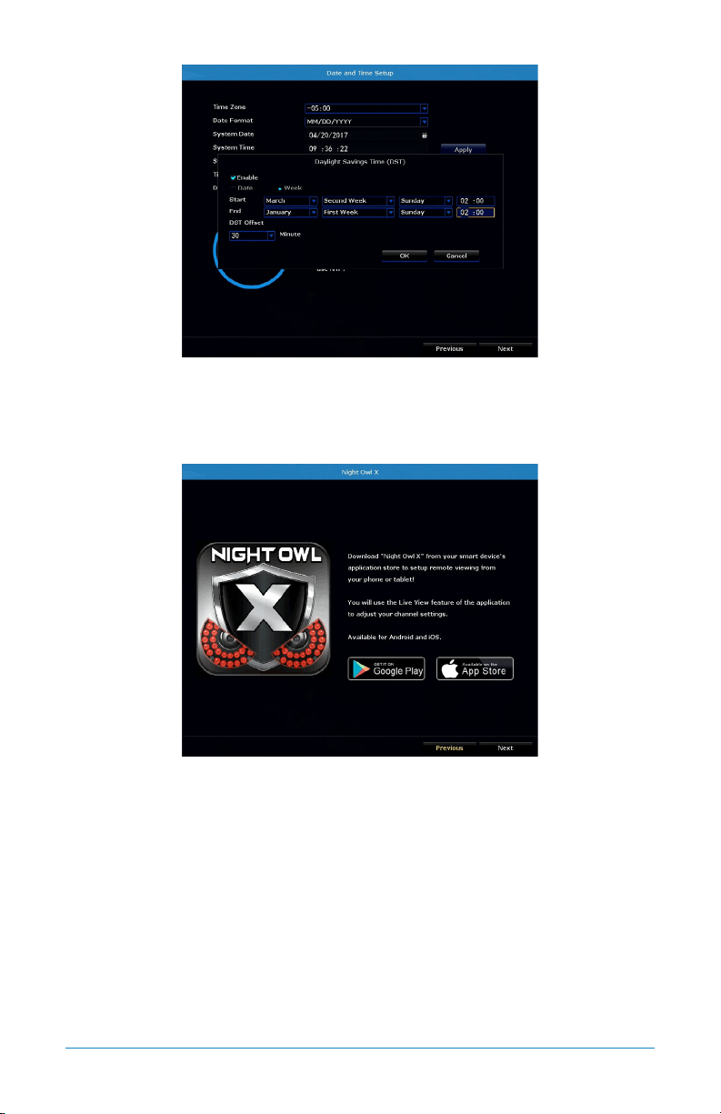
31Chapter 6: Getting Started
By selecting Setup, next to Daylight Savings Time (DST), you can adjust how your
NVR responds to DST.
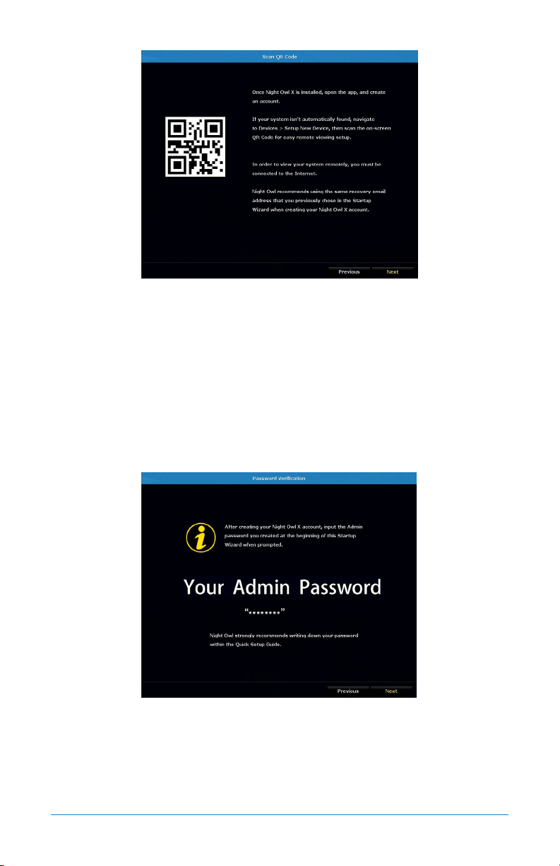
6.1.6 Night Owl X
The Night Owl X screen of the Startup Wizard gives you information on where
to find the Night Owl X app and how it can be used to remotely view your NVR
recordings and live stream.
32 WNVR Series User’s Manual
Once you have installed the Night Owl X app on your smart device and created an
account, you can scan the QR code on the Startup Wizard to configure your NVR
with the Night Owl X app!
Night Owl recommends using the same recovery email address that you previously
used in the Startup Wizard when creating your Night Owl X account.
NOTE: In order to view your system remotely, your NVR must be connected to
the Internet.
6.1.7 Password Verification
The Password Verification screen of the Startup Wizard will display your Admin
password. Night Owl strongly recommends storing your password on page 7 of your
NVR’s Quick Setup Guide.
33Chapter 6: Getting Started
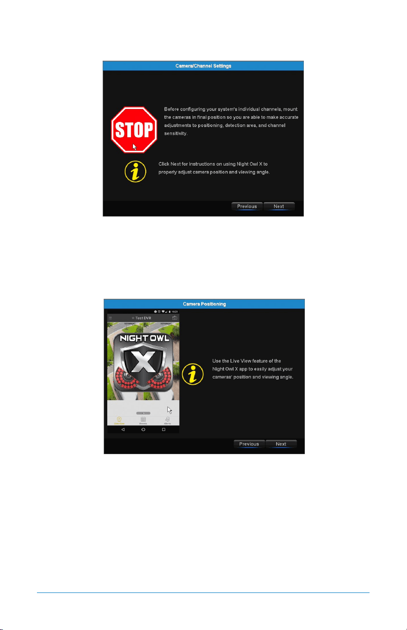
6.1.8 Camera/Channel Settings
The Camera/Channel Settings screen of the Startup Wizard serves as a reminder
to mount your system’s cameras in their final position so you can make accurate
adjustments to positioning, detection area and channel sensitivity.
6.1.9 Camera Positioning
The Camera Positioning screen of the Startup Wizard shows how you can use the
Live View feature of the Night Owl X app to easily adjust your camera’s position
and viewing angle.
34 WNVR Series User’s Manual
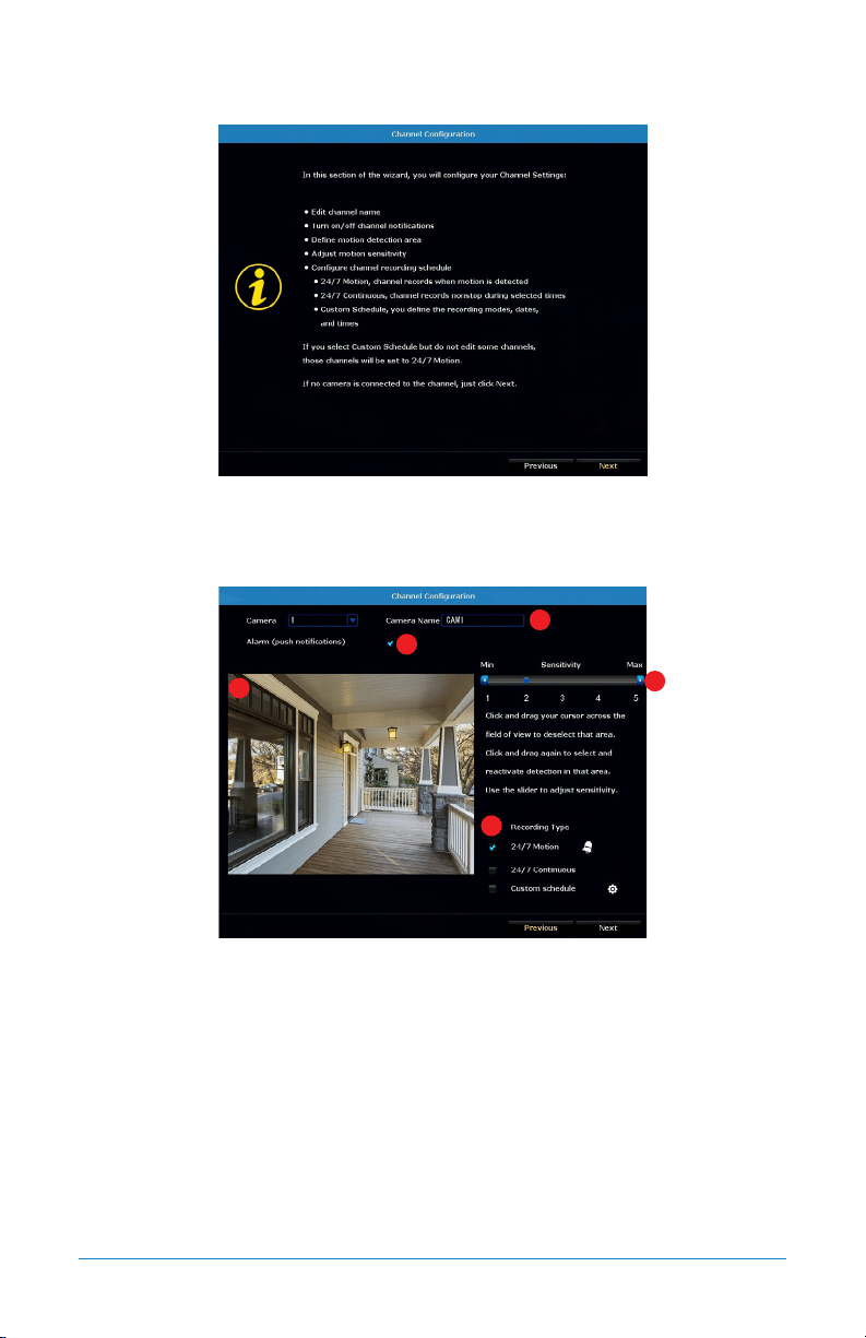
6.1.10 Channel Configuration
The Channel Configuration screen of the Startup Wizard explains in detail how you
will configure your channel settings. Please read this screen thoroughly as the
following screen will allow you to configure each channel settings.
The second Channel Configuration screen of the Startup Wizard allows you to
configure the following channel settings:
1. Edit channel name.
2. Turn on/off alarm (push notifications).
3. Define motion detection area.
4. Adjust motion sensitivity.
5. Configure channel recording schedule:
A. 24/7 Motion– channel records when motion is detected.
1
2
3
4
5
35Chapter 6: Getting Started
B. 24/7 Continuous– channel records non-stop during selected times.
C. Custom Schedule– you define the recording modes, dates and times.
NOTE: If you select Custom Schedule, but do not edit some channels, those
channels will be set to 24/7 Motion.
If no camera is connected to the channel, just click Next.
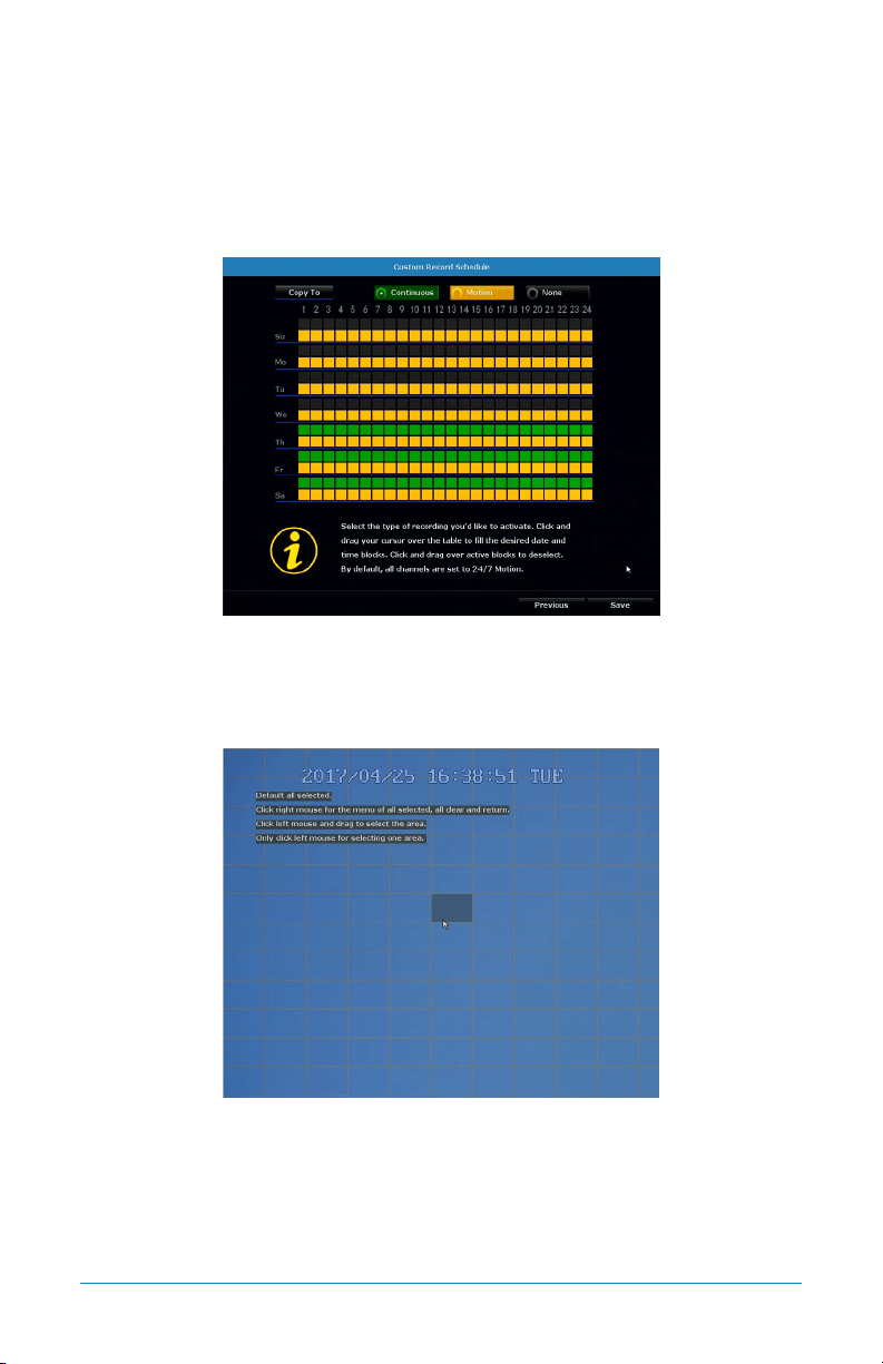
Select the type of recording you would like to activate. Click and drag your cursor
over the table to fill the desired date and time blocks. Click and drag over active
blocks to deselect. By default, all channels are set to 24/7 Motion.
To deselect an area, use your mouse to click on individual boxes. If you wish to
deselect the entire area, right click your mouse and choose Clear all. You may then
proceed to click and drag the area you want selected. To exit, right click your
mouse and choose Return.
36 WNVR Series User’s Manual
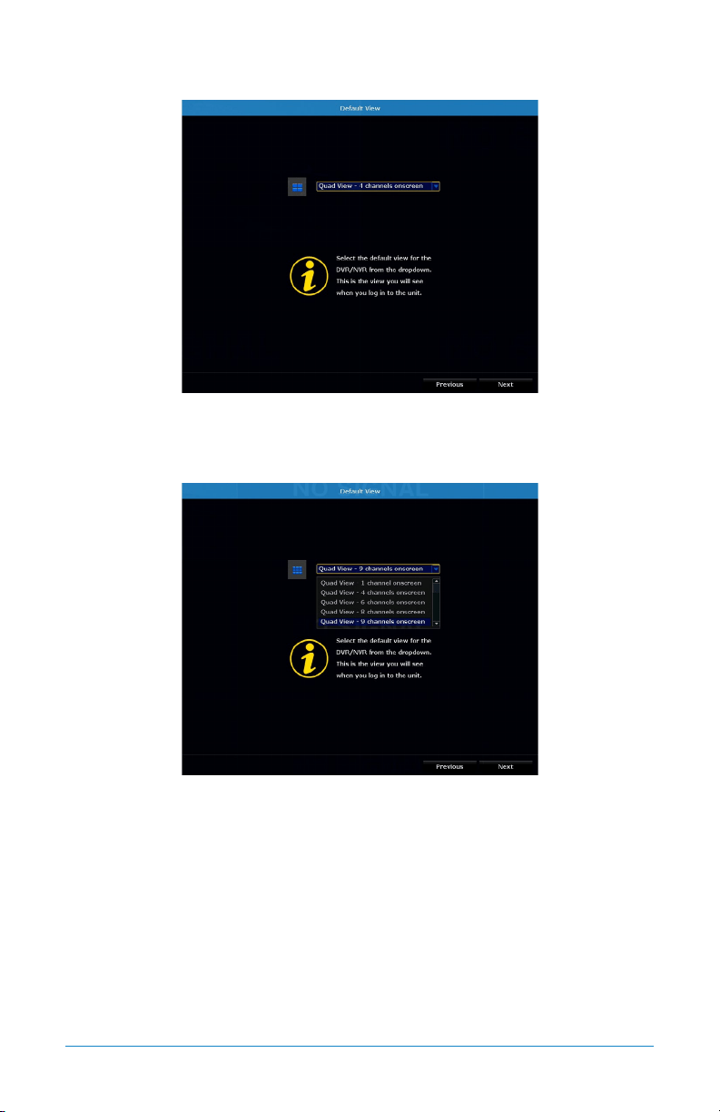
6.1.11 Default View
The Default View screen of the Startup Wizard allows you to select the default view
of the monitor connected to your NVR. You may select several viewing options from
the drop-down menu:
Quad View: 1 channel onscreen
Quad View: 4 channels onscreen
Quad View: 6 channels onscreen
Quad View: 8 channels onscreen
Quad View: 9 channels onscreen
37Chapter 6: Getting Started
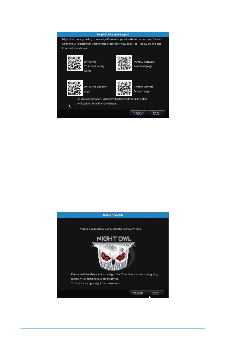
6.1.12 Helpful Links
The Helpful Links and Support screen of the Startup Wizard contains QR codes
linked to:
• NVR Troubleshooting Guide
• PC/MAC
®
software download page
• NVR Support page
• Remote Viewing Support page
For more information, visit www.NightOwlSP.com and click the Support tab at
the top of the page.
6.1.13 Wizard Complete
Once you have successfully completed the Startup Wizard, click Finish to begin
using your Night Owl NVR.
38 WNVR Series User’s Manual
6.2 Night Owl X Mobile App
The Night Owl X mobile app lets you access your NVR remotely with live viewing
from your tablet or smartphone. Download our free Night Owl X application from
the iTunes App or Google Play store.
Once you have downloaded Night Owl X and connected your NVR to your router,
you can network your NVR by scanning the QR code which is located on the top
of the NVR.
6.3 Live View (Login and Icons)
This section will discuss the Live View status icons and how to control and manage
your NVR using the channel toolbar and mouse menu.
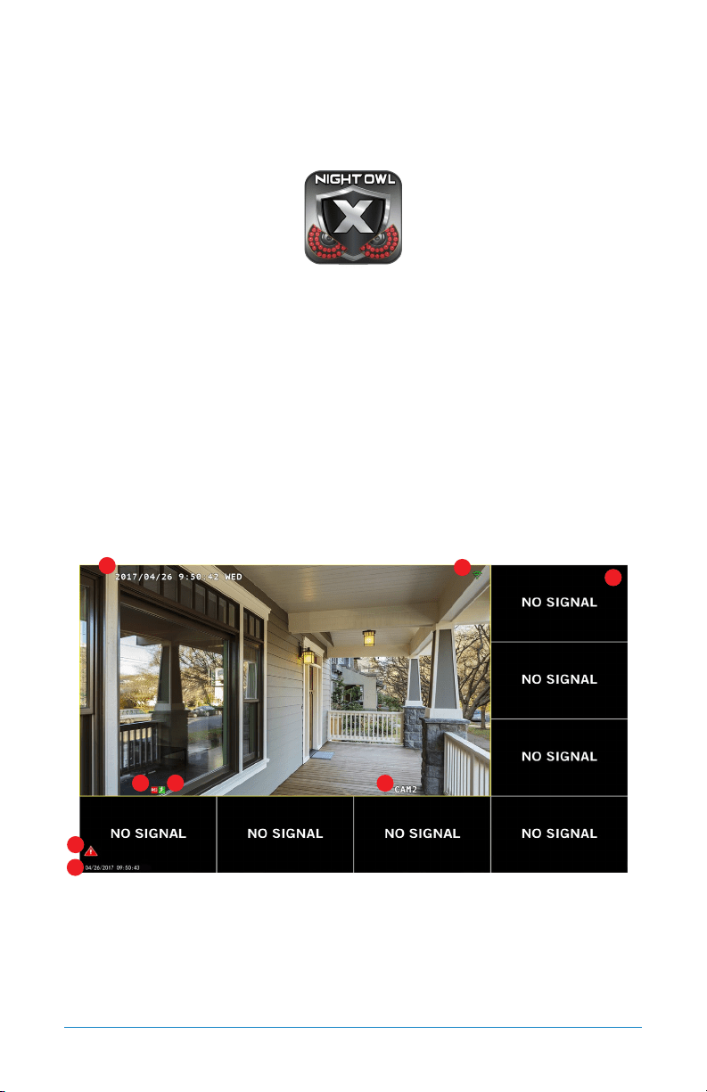
6.3.1 Live View (All Channels)
After you have completed the Startup Wizard for your NVR, you will see the Live View
screen. Live View is the default display mode of the NVR. It is the screen you will use
to watch live video feed from your NVR cameras and make select adjustments.
1. Date and Time OSD: Displays the date and time of your camera.
2. Signal Strength: Shows the signal strength of the camera.
3. Motion Detection Icon: Indicates that an alarm event such as motion
detection, video loss or tampering has occurred.
4. NVR status Recording Icon: Indicates that the NVR is currently recording
1
2
34
5
6
8
7
39Chapter 6: Getting Started
video from that camera. This icon will be the same whether the recording is
scheduled, initiated manually or triggered by motion.
5. Camera Name OSD: Shows the camera name.
6. System Exception Icon: Indicates that an alarm event or exception has occurred.
Click the icon to access the Alarm/Exception Information log where you can find
specific details about the event.
7. Date and Time: Shows the date and time of your NVR.
8. No Signal: Shows empty channels without a camera connected.
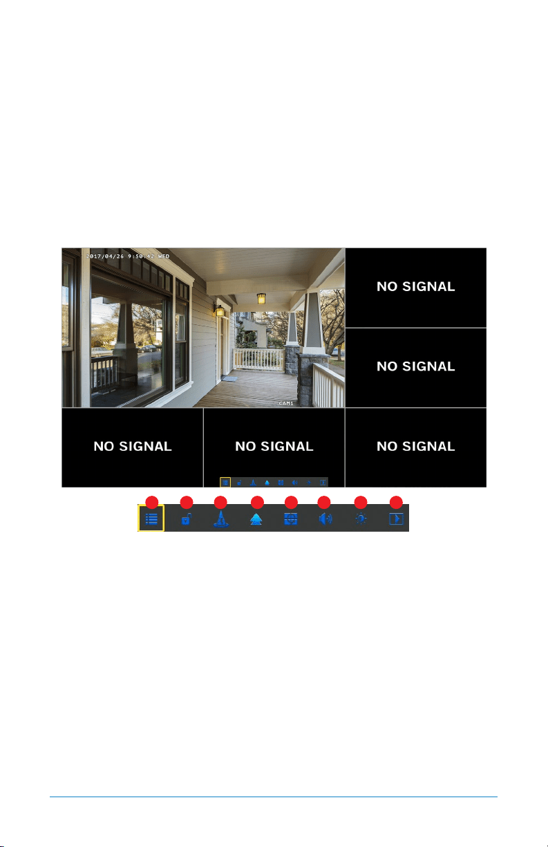
6.3.2 Right Click Menu
1. Menu: Opens the Main Menu.
2. Lock: Locks the system (log out), making it necessary to enter the password
to access any NVR menus.
3. Startup Wizard: Launches the Startup Wizard.
4. Multi-Camera View: Select a multi-screen viewing option, where you’ll be able
to see multiple video feeds at once.
5. Slide Show: Turns on sequence mode to automatically rotate channel views
at specific intervals (also known as Dwell Time).
6. Audio: Controls live audio volume.
7. Image Settings: Allows you to adjust certain image settings.
8. Video Playback: Opens the Video Playback menu.
1 2 3 4 5 6 7 8
40 WNVR Series User’s Manual
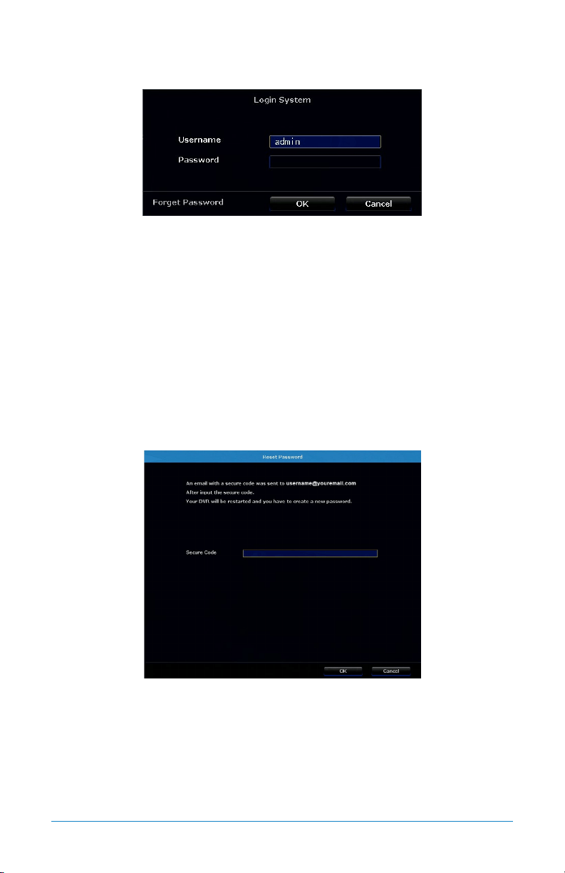
6.3.3 Login/Forgot Password
Anytime you want to configure or adjust your system settings you will be required to
log in by entering your username and password. It’s important you save your login
information or you won’t be able to access your NVR. We strongly recommend that
you store your password on page 7 of your QSG.
Username: Admin (all lowercase) is the default username. If additional were
created, you can switch between them.
Password: Enter the password you created during the Startup Wizard.
Forgot Password: Sends a secure code to your recovery email address. Once you
input the secure code, your NVR will restart and you will be required to create a
new password.
If you select Forgot Password, you will be directed to this screen. Simply enter the
secure code that was emailed to your recovery email address and then select OK.
Your NVR will then be restarted and you will be required to create a new password.
41Chapter 6: Getting Started
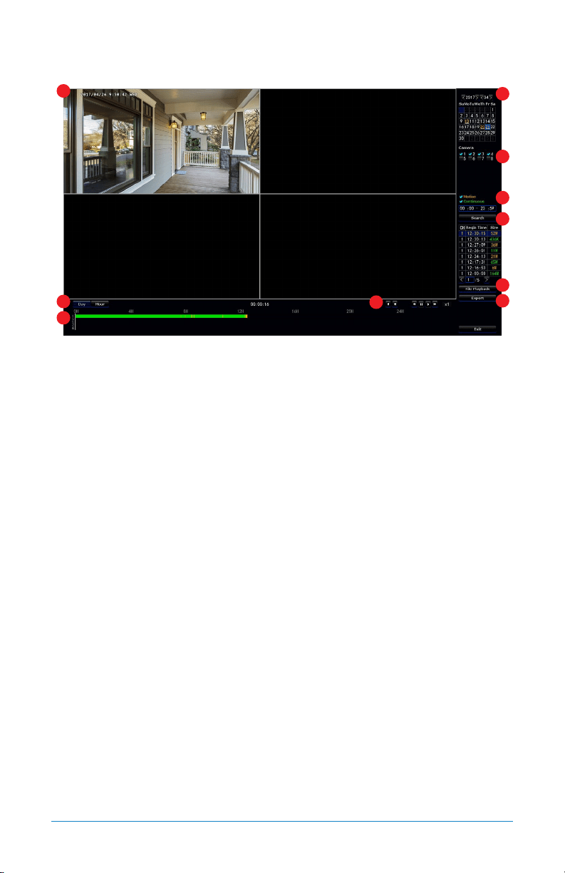
6.4 Video Playback
1. Video Image: Shows an image of the cameras that have video for the search
parameters entered.
2. Date: Allows you to search by date.
3. Camera: Allows you to search certain cameras.
4. Motion/Continuous: Allows you to search for Motion or Continuous recordings.
5. Search: Activates the search based on the criteria established above and shows
the recordings found on the table below.
6. File Playback: Allows you to focus in on the video recording selected in the
table above and control the recording.
7. Export: Allows you to export a recording onto a USB flash drive.
8. Day/Hour: Allows you to switch the timeline between a day or hour scale.
9. Timeline: Shows the presence of a video recording and shows the progress of
the video.
10. Controls: Allows you to control (rewind, fast-forward, pause, play, etc.) a video.
1
2
3
4
5
6
7
8
9
10

42 WNVR Series User’s Manual
CHAPTER 7
MENUS
AND SETTINGS
43Chapter 7: Menus and Settings
Chapter 7: Menus and Settings
Some menu screens will allow you to copy similar settings to multiple channels.
Choose the channel you would like to copy information from in the first drop-down box
(Copy), then select the channel you would like to copy the information to from the
second drop-down box (To). Click Copy when the proper channels have been chosen.
Be sure to click Apply to save all changes you make
in the menus. If you do not save the changes, they
will not be applied. You can also select the Default button on
any page to restore default settings for those parameters.
44 WNVR Series User’s Manual
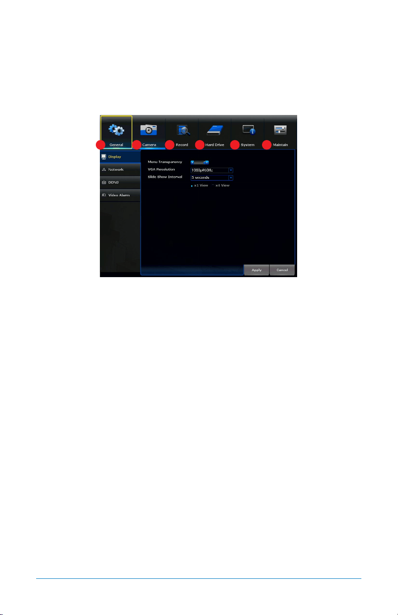
Menu
The main menu lets you access many of your NVR’s great features. You can customize
camera names, keep track of recent events, create recording schedules, configure
advanced motion detection settings, check up on the hard drive’s condition and
change other NVR settings.
1. General: Will allow you to access Display, Network, DDNS and Video Alarm
submenus and manage the settings for those categories for your NVR.
2. Camera: Will provide access to Status, Add Camera, On-Screen Display, Video
Quality and Camera Firmware Update submenus.
3. Record: Will provide access to Record Settings and Export Recordings submenus.
4. Hard Drive: Will provide access to the HDD menu, allow you to reformat your
HDD and make other changes.
5. System: Will allow access to System Settings, NVR WiFi Settings, User
Management, Device Info and Log and Camera Speed submenus.
6. Maintain: Will allow access to System Maintenance, Firmware Update and
Factory Default submenus.
1 2 3 4 5 6
45Chapter 7: Menus and Settings
7.1 General Menu
The general menu will allow you to access display and network settings for your
NVR system.
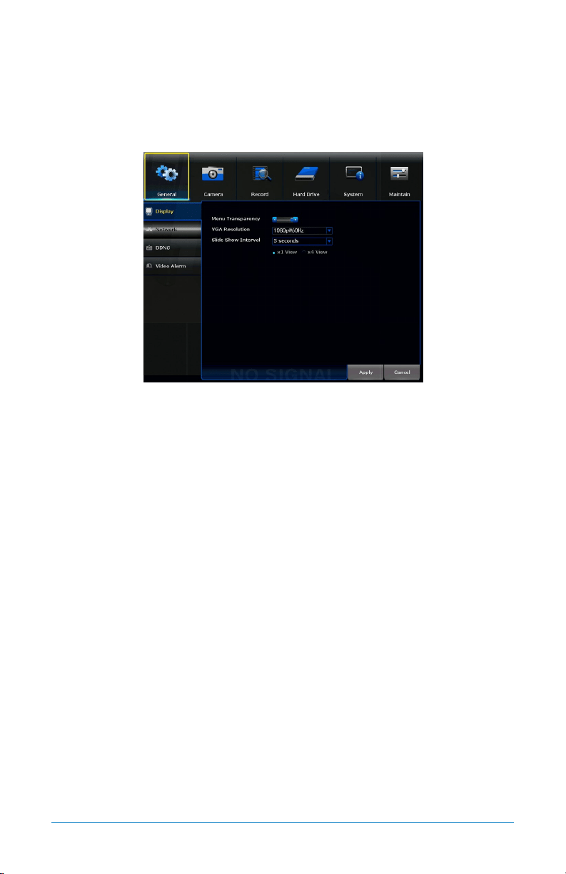
7.1.1 Display
Menu Transparency: Modify the menu transparency when displayed on screen.
VGA Resolution: Optimize the display resolution to best fit your TV/monitor. By
default, the optimal resolution will be auto-selected by the NVR.
Slide Show Interval: Adjust the duration each channel is displayed during
a sequential view. You can choose between 1 and 300 seconds per channel.
To begin the auto-sequence feature, click on the auto-sequence icon which is
located on the quick access bar.
46 WNVR Series User’s Manual
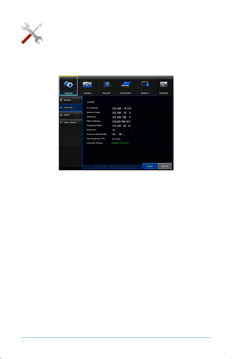
7.1.2 Network
Find network values and optimize connectivity based on your
Internet connection. In most cases the values should populate
automatically once your NVR is connected to the Internet. The
values in this section should only be adjusted if you are an advanced user and
have extensive experience in device networking.
DHCP: Network configuration mode that gathers the network values automatically
from DHCP server. If unchecked this value can be set manually.
IP Address: Network address of the connected NVR.
Subnet Mask: The range of IP addresses that can be found in the network. This
should always be set to the default address 255.255.255.000.
Gateway: The connection between two networks. This should always be the IP
address of the connected router.
MAC Address: The unique identifier assigned to network interfaces for
communications at the data link layer.
Preferred DNS: Domain Name System server address.
Web Port: Allows access to your NVR with your computer through your LAN or the
Internet. The default value is 80.
Network Bandwidth: Defines channel capacity, or the maximum throughput of the
network interface.
Net Diagnose Info: Allows you to Enable or Disable the network status availability.
Network Status: Shows status of the network connectivity.
ADVANCED
47Chapter 7: Menus and Settings
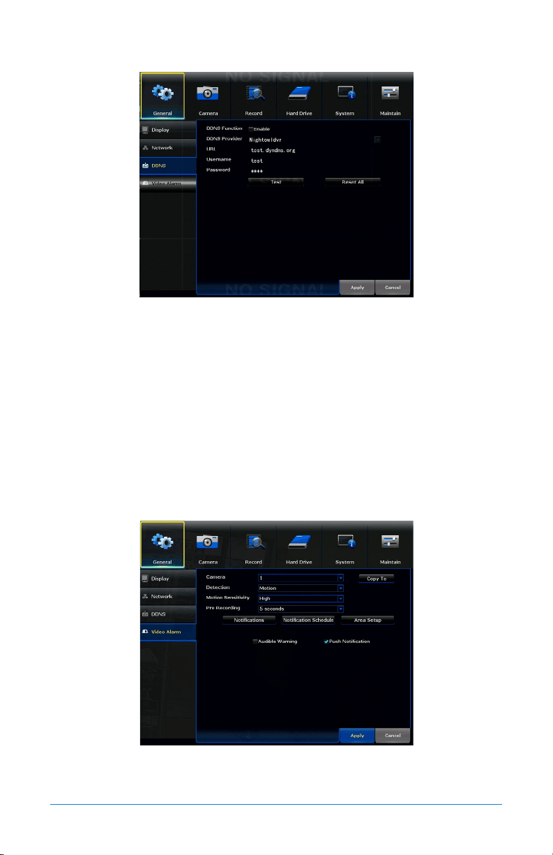
7.1.3 DDNS
DDNS Function: Enable or disable the usage of the DDNS service on the NVR.
DDNS Provider: Set to the NightowlNVR server when using the Night Owl free
domain name server. (default and only option).
URL: Set to the URL name you created when registering your DDNS.
Username: The User ID created during the DDNS registration process.
Password: The password created during the DDNS registration process.
Test: Tests to ensure the configuration set is correct.
Reset All: Restores the configuration to default values.
7.1.4 Video Alarm
Camera: Select the camera for which you want to adjust motion alarm settings.
Detection: Enable motion alarms.
48 WNVR Series User’s Manual
Motion Sensitivity: Adjusts the sensitivity of the motion sensor for the camera
selected. A lower setting will require more movement in the camera range to
begin recording.
Pre-Recording: Number of seconds that are pre-recorded before motion is detected.
Copy To: Allows you to copy this menu’s settings from one camera to another.
Notifications: Displays options to Enable or Disable Audible Warning and
Push Notification.
Notification Schedule: Allows you to set a notification schedule.
Area Setup: Area Setup will allow you to configure the motion detection area. Blue
boxes denote areas that will detect motion whereas uncolored boxes denote areas
that will not detect motion. When finished, right click return to the menu.
Audible Warning: Enable or Disable the internal NVR buzzer that sounds when
motion is detected.
Push Notification: Enable or Disable the push notifications being sent to your
smart device.
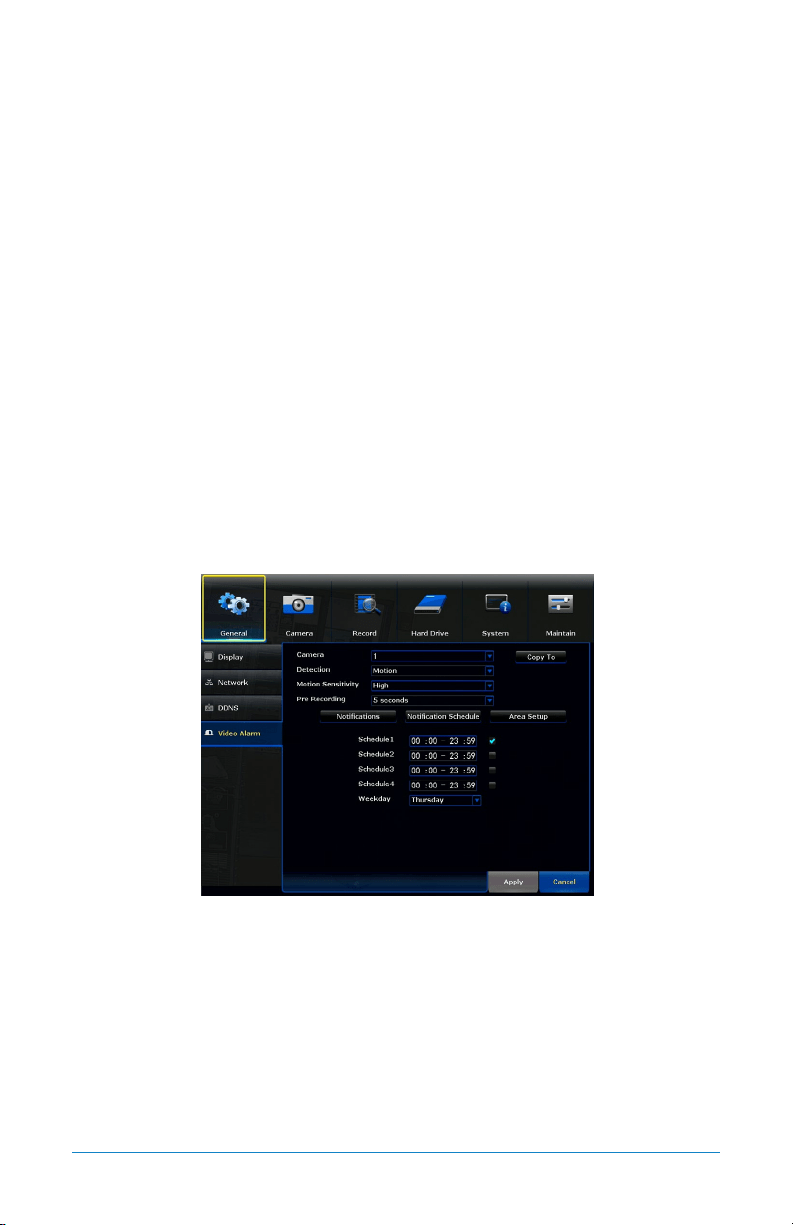
7.1.4 (a) Notification Schedule
Schedule #: Allows you to set up to 4 ranges throughout the day where motion
alerts will be sent to your smart device.
Weekday: Allows you to select which day the schedule applies to.
49Chapter 7: Menus and Settings
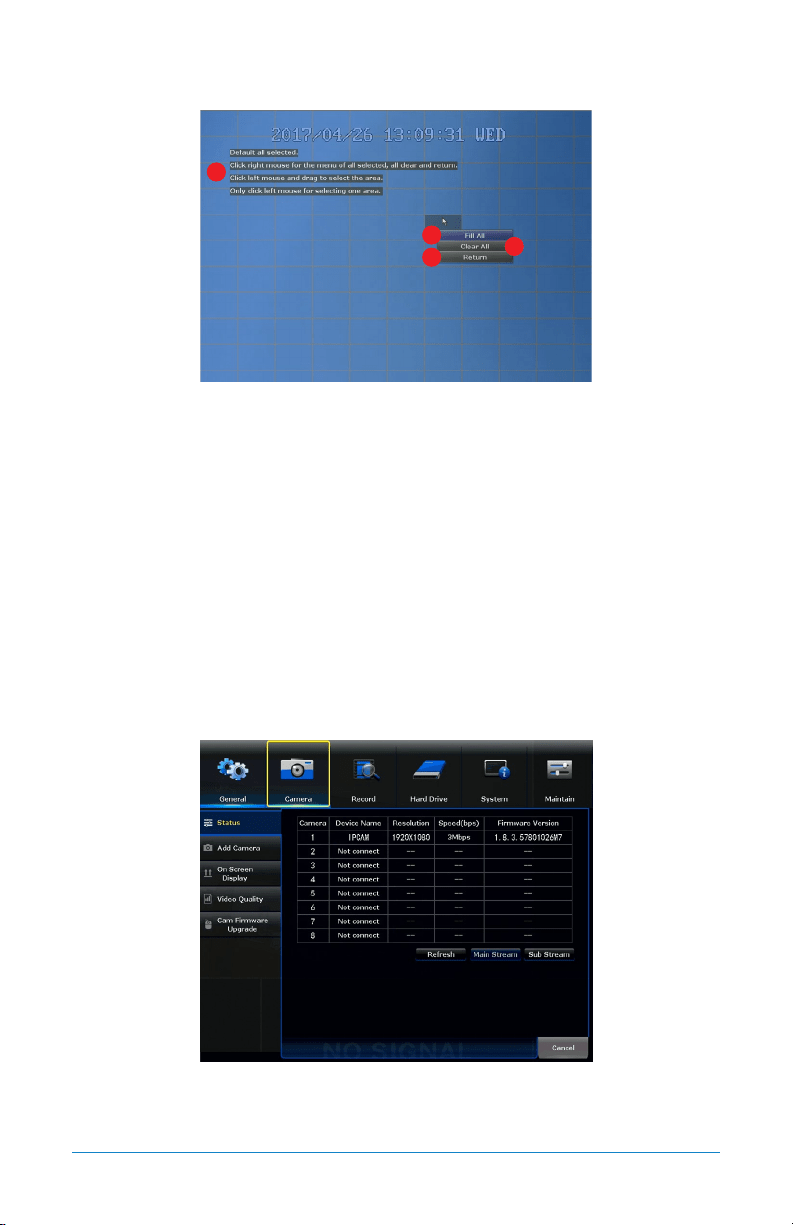
7.1.4 (b) Area Setup
1. Instructions: A series of instructions on how to set the motion detection area.
Blue boxes denote areas that will detect motion whereas uncolored boxes denote
areas that will not detect motion. When finished, right click to return to the
menu and click Apply to save changes.
2. Fill All: Selects the entire screen for motion detection.
3. Clear All: Deselects the entire screen and prevents motion alerts/recordings
from being triggered.
4. Return: Returns to the Video Alarm submenu.
7.2 Cameras Menu
Adjust or modify individual camera settings connected to your NVR.
7.2.1 Status
Table: Table shows the cameras connected to the NVR, the resolution of the main
or sub stream video, the maximum speed at which that stream will be transmitted
and the firmware version of the camera.
1
2
3
4
50 WNVR Series User’s Manual
Refresh: Refreshes the information in the table.
Main Stream: Shows main stream resolution in the table.
Sub Stream: Shows sub stream resolution in the table.
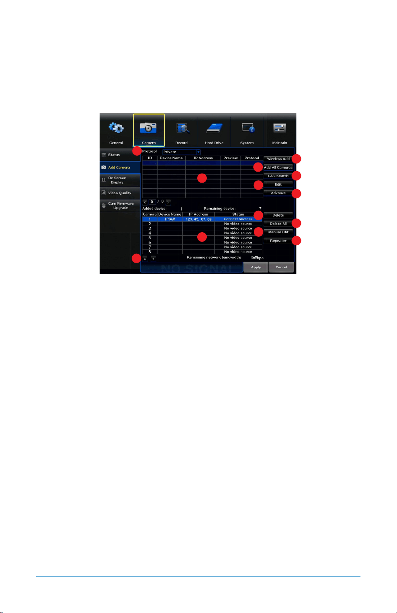
7.2.2 Add Camera
1. Protocol: Establishes the protocol used by the NVR when it is looking for
cameras to pair with.
2. Table 1: Shows the cameras available to pair with the NVR.
3. Table 2: Shows the cameras already paired to the NVR.
4. Wireless Add: Initiates the discovering and pairing process for available
wireless cameras.
5. Add All Cameras: Pairs all cameras in Table 1 with the NVR and places those
cameras in Table 2, so long as the number of cameras in Table 1 does not
exceed the number of available channels on the NVR. This option also will
allow pair cameras that are not in the same network segment as the NVR.
6. LAN Search: Initiates the discovery of cameras over the same network segment
where the NVR is connected.
7. Edit: Allows the network parameters of the cameras in Table 1 to be modified.
8. Advance: Allows advanced options to be Enabled or Disabled.
9. Delete: Will delete the selected camera from Table 2 and move it to Table 1.
10. Delete All: Will delete all cameras from Table 2 and move them to table 1.
11. Manual Edit: Allows the channel connection parameters of the cameras in
Table 2 to be modified.
1
2
3
4
5
6
7
8
9
12
11
10
13
51Chapter 7: Menus and Settings
12. Repeater: Opens a window which allows for an extended network to be built,
using the cameras as repeaters of the Wi-Fi signal.
13. Arrows: Allows you to move the selected camera to a different channel.
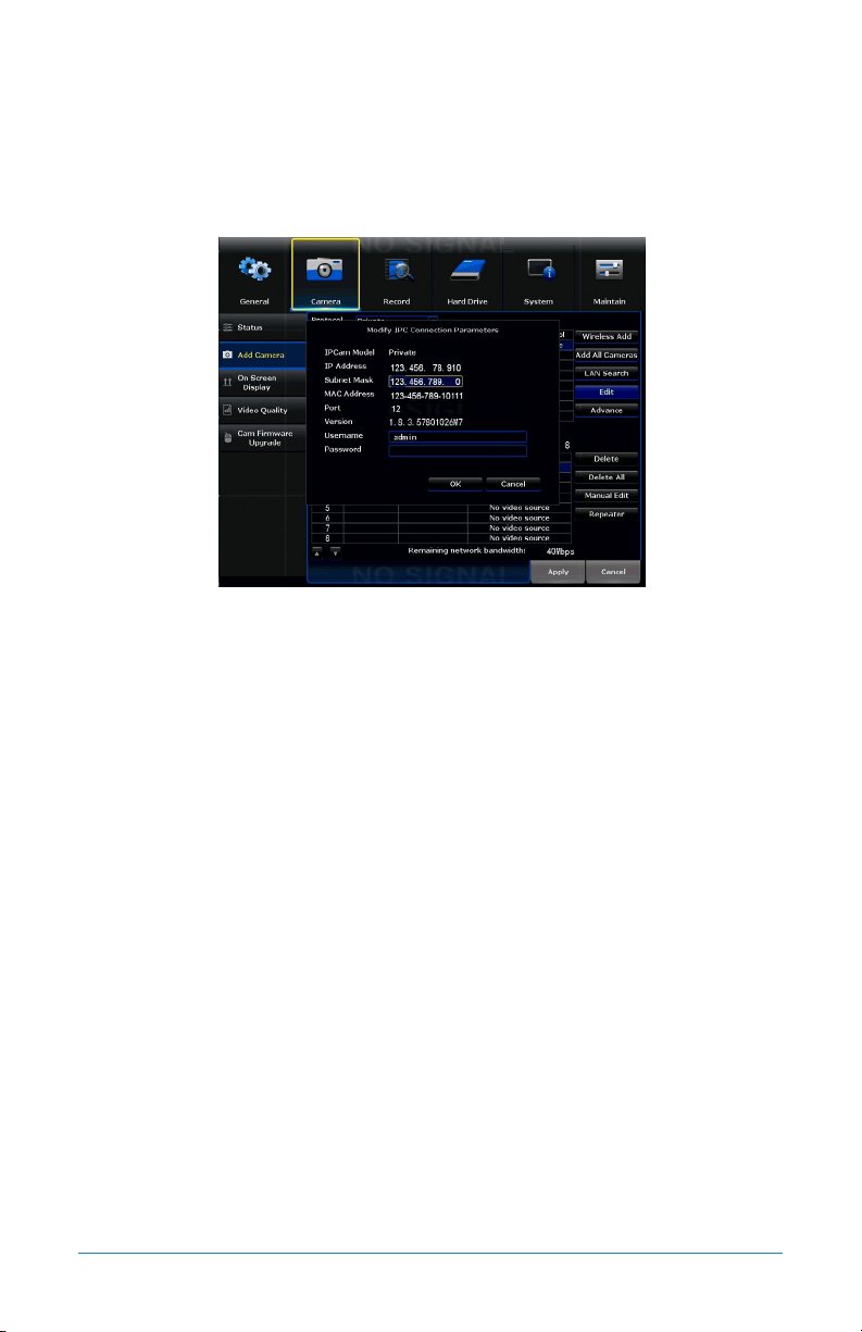
7.2.2 (a) Edit
IPCam Model: Shows the protocol of the camera.
IP Address: Network address of the connected camera.
Subnet Mask: The range of IP addresses that can be found in the network. This
should always be set to the default address 255.255.255.000.
MAC Address: The unique identifier assigned to the network interface of the
camera for communications at the data link layer.
Port: Allows access to your camera with your computer through your LAN or the
Internet. The default value is 80.
Version: Shows the firmware version of the camera.
Username: Shows the username of the credentials needed to establish a
connection with the camera. By default, admin.
Password: Shows the password of the credentials needed to establish a
connection with the camera. By default, password field should be empty.
52 WNVR Series User’s Manual
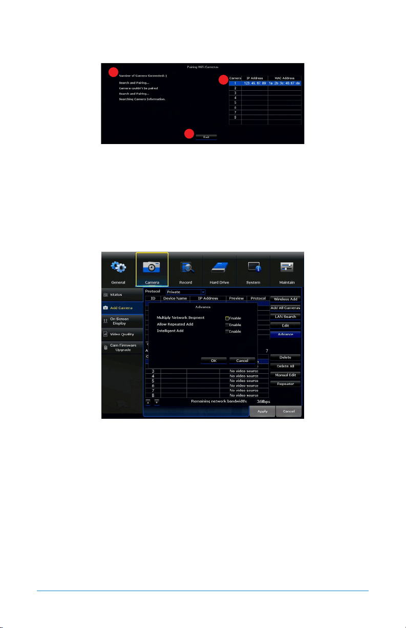
7.2.2 (b) Wireless Add
1. Number of Cameras Connected: Shows the number of cameras paired to the NVR.
2. Camera Table: Shows the IP Address and MAC Address of all the cameras
already paired to the NVR.
3. Exit: Return you to the Add Camera submenu.
7.2.2 (c) Advance
Multiply Network Segment: Enable or Disable the capability to add wireless
cameras not provided by Night Owl.
Allow Repeated Add: Allows you to keep the cameras in Table 2 in Table 1 as well.
Intelligent Add: Allows you to add cameras in different network segments, other
than the NVR.
1
2
3
53Chapter 7: Menus and Settings
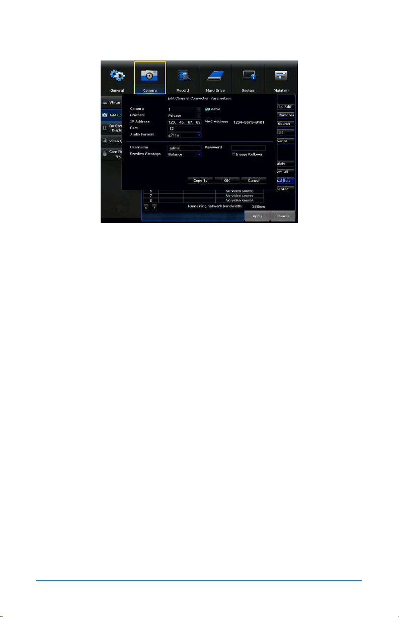
7.2.2 (d) Manual Edit
Camera: Select the camera you want to edit.
Protocol: Shows the protocol of the selected camera. Private (Night Owl),
ONVIF (Standard).
IP Address: Network address of the connected camera.
Port: Allows access to your camera with your computer through your LAN or the
Internet. The default value is 80.
Audio Format: Audio codec used for the two-way audio communication. The
default value is G711a but G711u can also be used.
Enable: Will Enable (turn on) and Disable (turn off) the camera video stream.
MAC Address: The unique identifier assigned to the network interface of the
camera for communications at the data link layer.
Username: Shows the username of the credentials needed to establish a
connection with the camera. By default, admin.
Preview Stratage: Used for live view. If the signal of the connected camera to the
NVR is not strong enough to sustain a decent quality image, this function can adjust
the mainstream transmission to improve video quality.
Password: Shows the password of the credentials needed to establish a
connection with the camera. By default, password field should be empty.
Image Rollover: Will invert or reestablish the video image from the selected camera.
54 WNVR Series User’s Manual
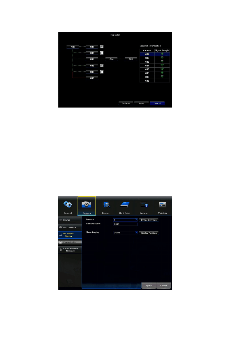
7.2.2 (e) Repeater
Diagram: Shows the dependency of the Wi-Fi signal for each camera connected.
What is shown in the above diagram is CH1, CH2, CH3, CH6 and CH7 connected
directly to the NVR, CH4 connected in Daisy Chain to CH3 where CH3 works also
as a repeater and CH5 connected in Daisy Chain to CH4 where CH4 works also as
a repeater. The CH8 is disconnected.
Table: Shows the signal strength off each connected camera.
Refresh: Will update the diagram with any changes made.
Apply: Will apply any changes made.
7.2.3 On Screen Display
Camera: Allows you to select which camera to modify.
Camera Name: Shows the current name and allows you to edit the name of the
selected camera.
Image Settings: Allows to modify video image settings for the selected camera.
55Chapter 7: Menus and Settings
Show Display: Enable or Disable the functionality of Display Position.
Display Position: Allows you to move the camera to a different channel.
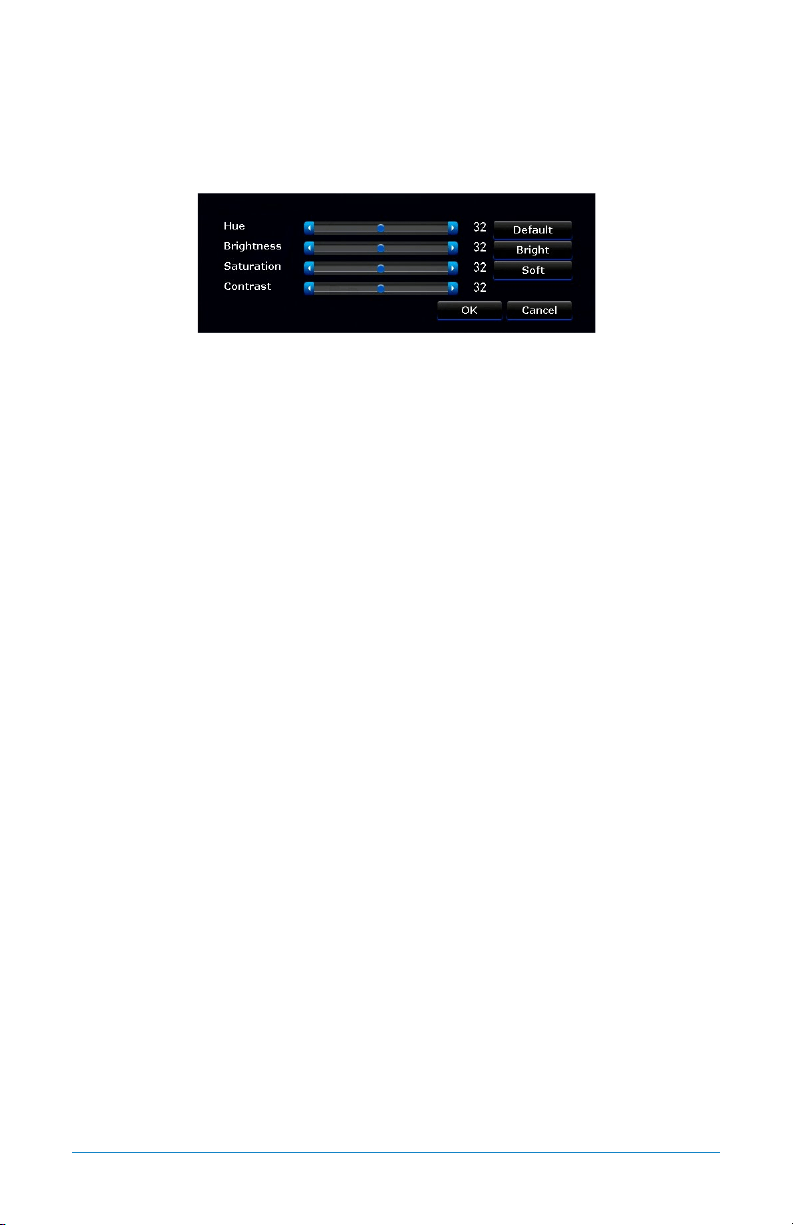
7.2.3 (a) Image Settings
Hue: Changes the color mix of the image.
Brightness: Changes how light the image appears. This feature does not extend or
enhance night vision mode.
Saturation: Alters how much color is displayed in the image. The higher the
saturation, the more bright and vivid colors will appear.
Contrast: Increases the difference between the blackest black and the whitest
white in the image. Useful if sections of the image are “grayed out”. However,
setting the contrast too high will degrade the image quality.
Default: Resets the image to its default values.
Bright: Sets a predefined value to show a brighter image.
Soft: Sets a predefined value to show a softer image.
7.2.3 (b) Display Position
Position: Places the selected camera in the position chosen from the dropdown menu.
56 WNVR Series User’s Manual
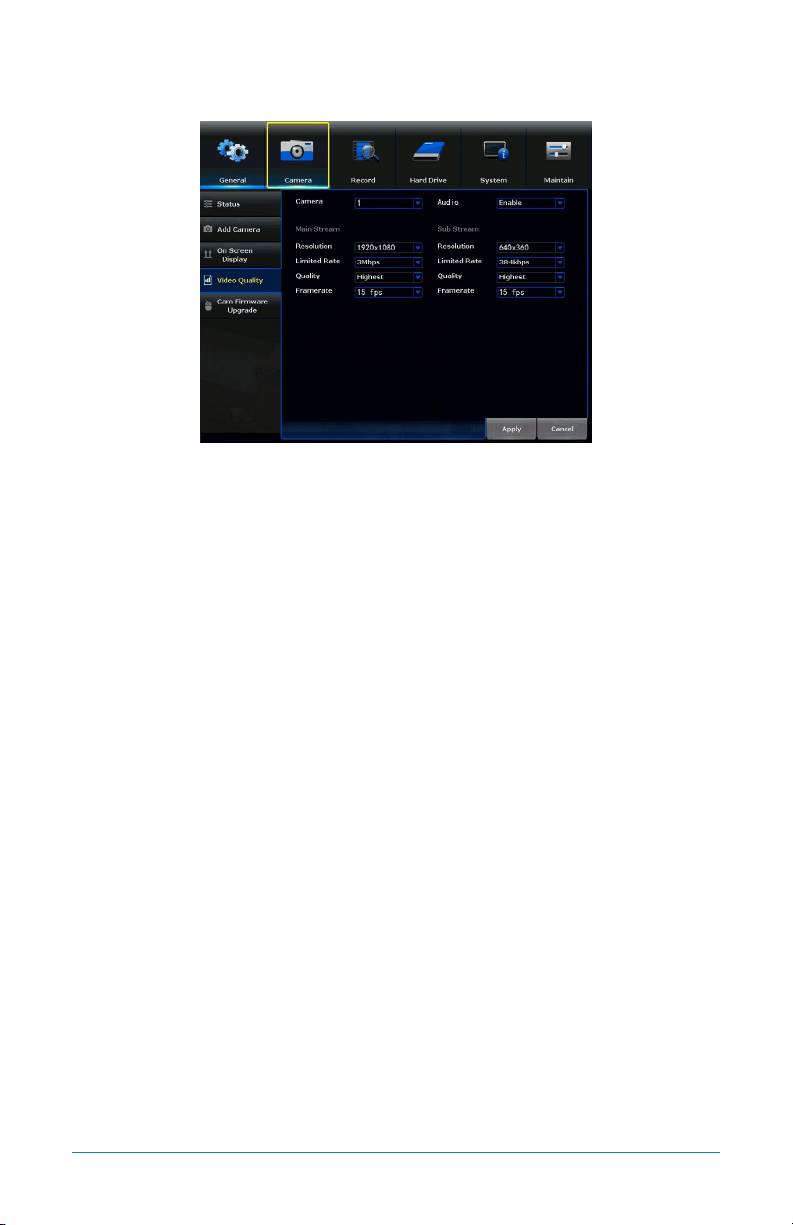
7.2.4 Video Quality
Camera: Select which camera to edit.
Resolution: Choose a resolution based on your TV or monitor capabilities.
Resolution by default is 1080p (1920 x 1080).
Limited Rate: Adjusts the amount of data transferred while streaming. The default
setting is sufficient for most networks.
Quality: By default, quality is set to Highest.
Framerate: Increases or decreases the frames per second of the streaming video,
depending on your connection speed. Higher FPS equals better video quality. If
experiencing lag or stutter, lower the FPS.
Audio: Enable or Disable audio recordings on the camera selected.
Main Stream/Sub Stream: Sub stream values are set for an image with less
bandwidth consumption (less resolution and limited rate).
57Chapter 7: Menus and Settings
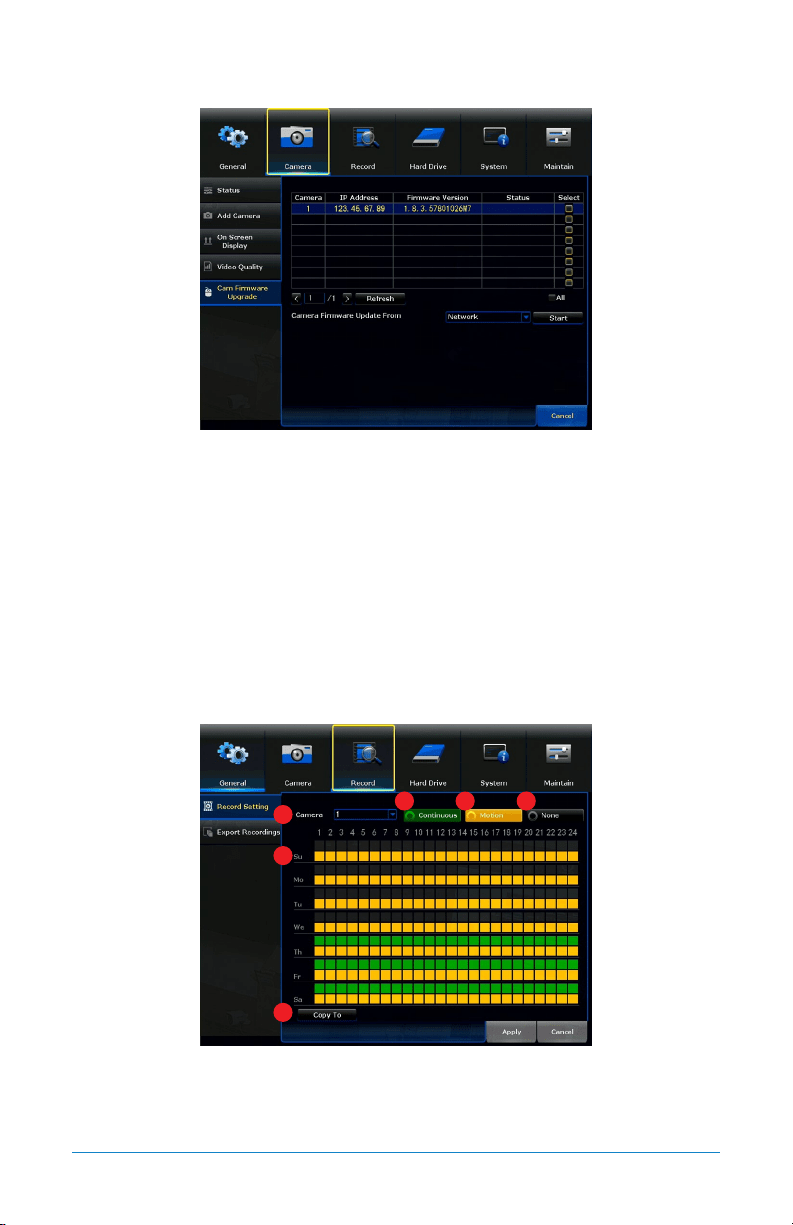
7.2.5 Cam Firmware Upgrade
Table: Shows the IP and firmware version of all connected cameras.
Camera Firmware Update From: Allows you to choose the source of the firmware
upgrade (Network or USB). Network is preferred.
Start: Begins the process of updating the firmware of the selected camera.
7.3 Record
The Record menu will allow access to the Record Settings and Export Recordings
submenus. From these submenus, it will be possible to manage the settings for
those categories.
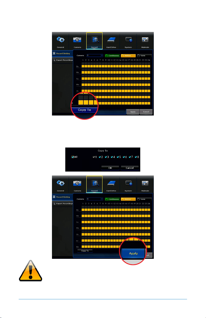
7.3.1 Schedule
1. Camera: Choose which camera to edit.
2. Continuous: Enable the selection of the continuous recording in the time diagram.
3. Motion: Enable the selection of the motion recording in the time diagram.
1
2 3 4
5
6
58 WNVR Series User’s Manual
4. None: Disable the selection of both continuous and motion recordings.
5. Time Diagram: Shows a diagram (hours of the day x day of the week). Use
this diagram to apply motion recordings and/or continuous recordings during
specified periods.
6. Copy To: Allows you to copy the configuration for one camera to another.
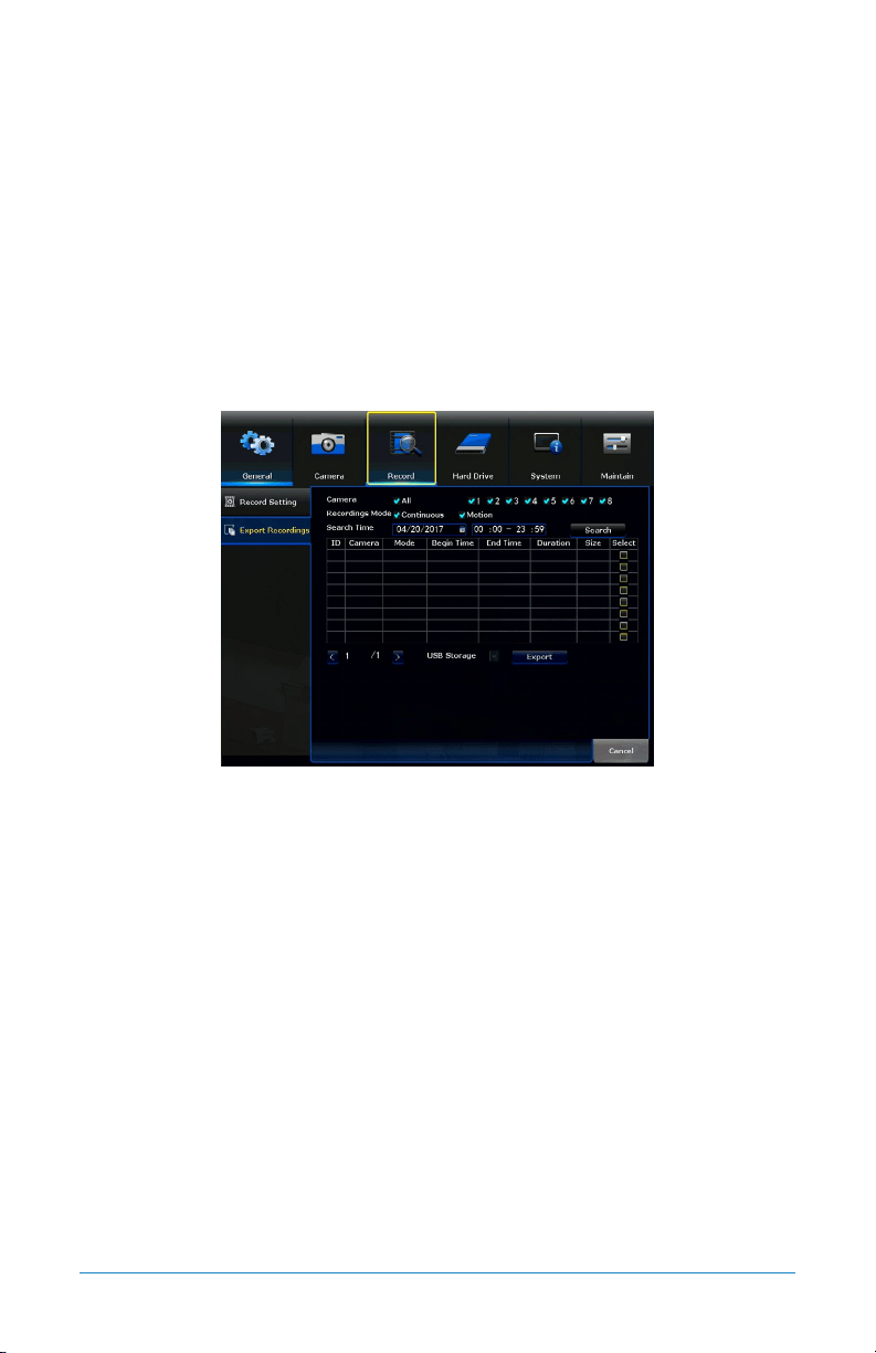
7.3.2 Export Recordings
Search and playback all recorded video from this menu. Choose your desired date
and times from the options below, then click Play to view recorded video. Right-
click to exit back to the menu screen.
Camera: Select which camera(s) to search for recordings.
Recording Mode: Select which recording type to search for. Choose Continuous,
Motion or both.
Search Time: Set a date and time range to search for recordings.
Table: Shows all the recordings found with current search parameters.
Storage: Allows you to backup recordings. By default, USB Storage (flash drive
or external HDD).
Export: Lets you export a recording located in the table to the selected storage.
59Chapter 7: Menus and Settings
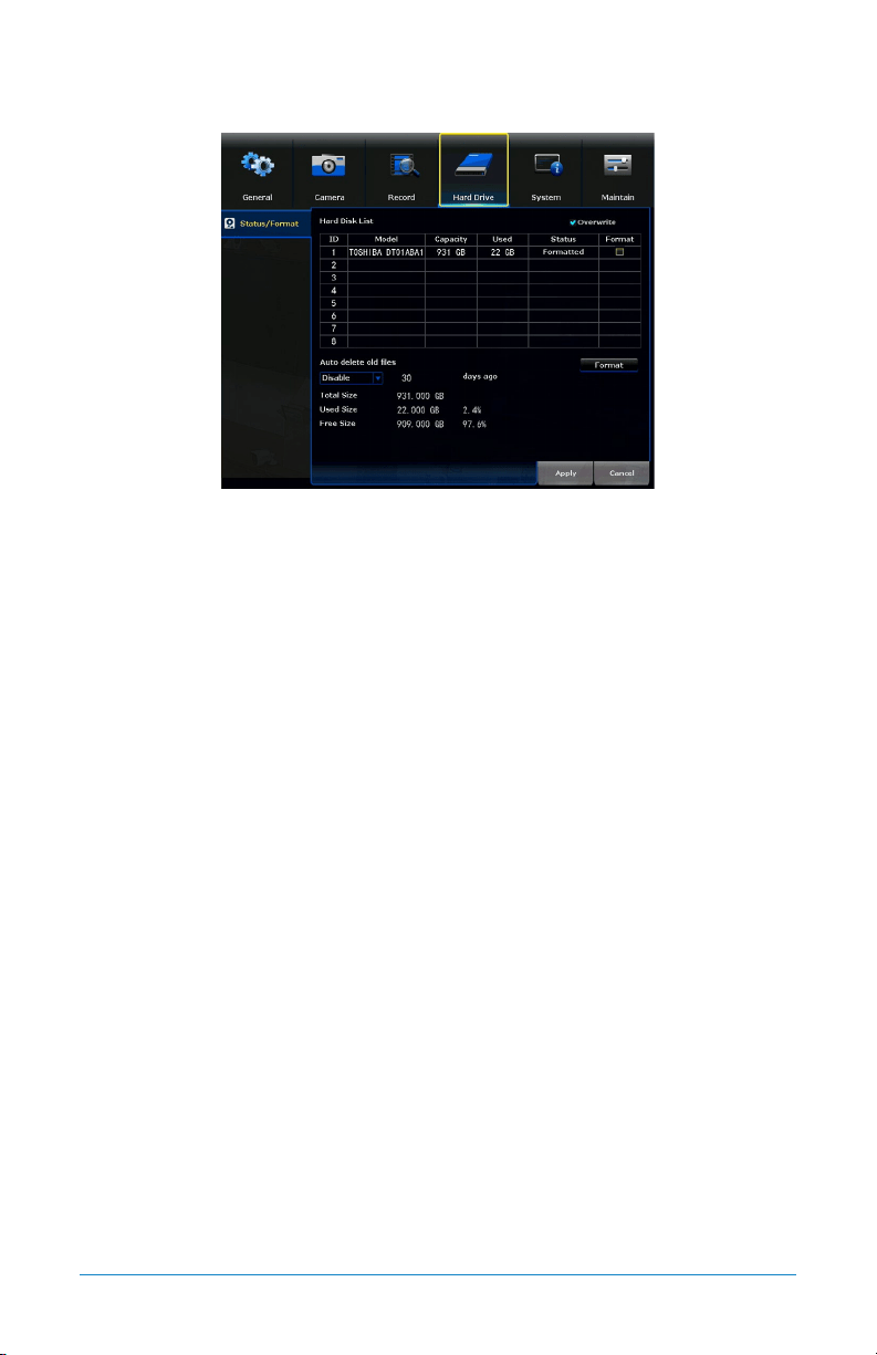
7.4 Hard Drive
Hard Disk List: List of all the hard drives, including their characteristics,
installed on the NVR.
Format: Reformats the HDD, erasing all stored recordings. If the HDD is
malfunctioning, a reformat is recommended before replacement.
Disable: Allows you to choose Disable or Enable the automatic deletion of old
files. This feature, if Enabled, will automatically delete all files not within the
specified day range.
Overwrite: Old footage is automatically recorded over when the HDD becomes
full. Overwrite is selected by default.
60 WNVR Series User’s Manual
7.5 System
The System menu will allow access to the System Settings, including, NVR WiFi
Settings, User Management, Device Info, Log and Camera Speed submenus.
From these submenus, it will be possible manage the settings for those
categories of the NVR.
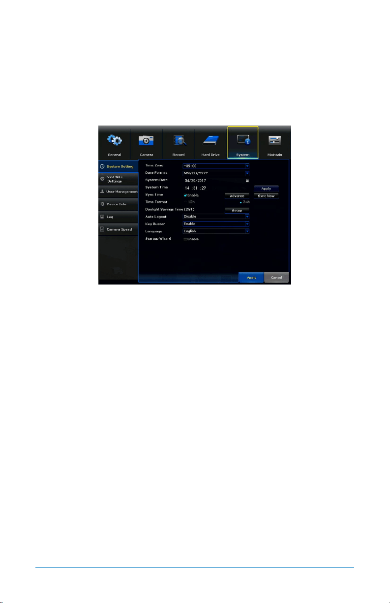
7.5.1 System Settings
Time Zone: Select the correct time zone for your location.
Date Format: Choose the display format for the date. You can select Month/Day/Year,
Year/Month/Day or Day/Month/Year.
System Date: Will show the current date set on the system.
System Time: Will show the current time.
Sync Time: Enables or Disables NTP (Network Time Protocol) services.
Time Format: Select either a 12Hour or 24Hour format.
Daylight Saving Time: Configure daylight savings times by selecting Setup.
Auto Logout: Enable or Disable auto logout. If Disabled, the NVR will remain
logged in.
Key Buzzer: Allows remote control of NVR (future versions).
Language: Choose between English, Spanish and French.
Startup Wizard: If Enabled, the Startup Wizard will launch every time the
system reboots.
Advance: For advanced NTP configuration.
Apply: Applies all changes made.
Sync Now: Manually syncs the configured NTP service.

61Chapter 7: Menus and Settings
7.5.1 (a) Advance
Sync Time Server: Choose which NTP server to sync the date and time with.
Preference Host: Allows the user to set the desired NTP server.
Auto Sync Time: Determine how often the NTP server will sync.
Schedule: Schedule the NTP server sync.
7.5.1 (b) Setup
Enable: Enable or Disable the DST.
Date: Determine the dates and times for the DST.
DST Offset: Determine the time offset to be altered during DST.
62 WNVR Series User’s Manual
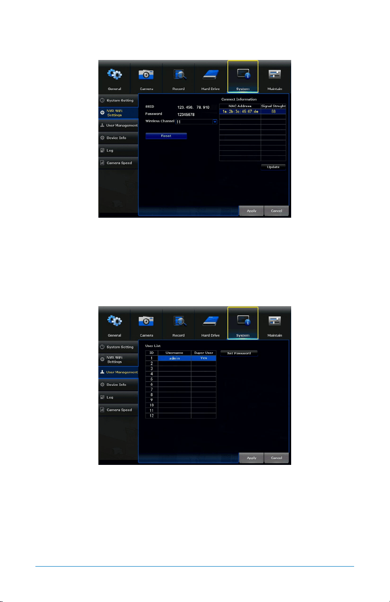
7.5.2 NVR WiFi Settings
SSID: The SSID of the NVR.
Connect Information: Lists all of the MAC addresses for connected cameras and
their signal strength.
7.5.3 User Management
Set Password: Change the password for the selected user.
User List: Lists of all the users that have access to the NVR.
63Chapter 7: Menus and Settings
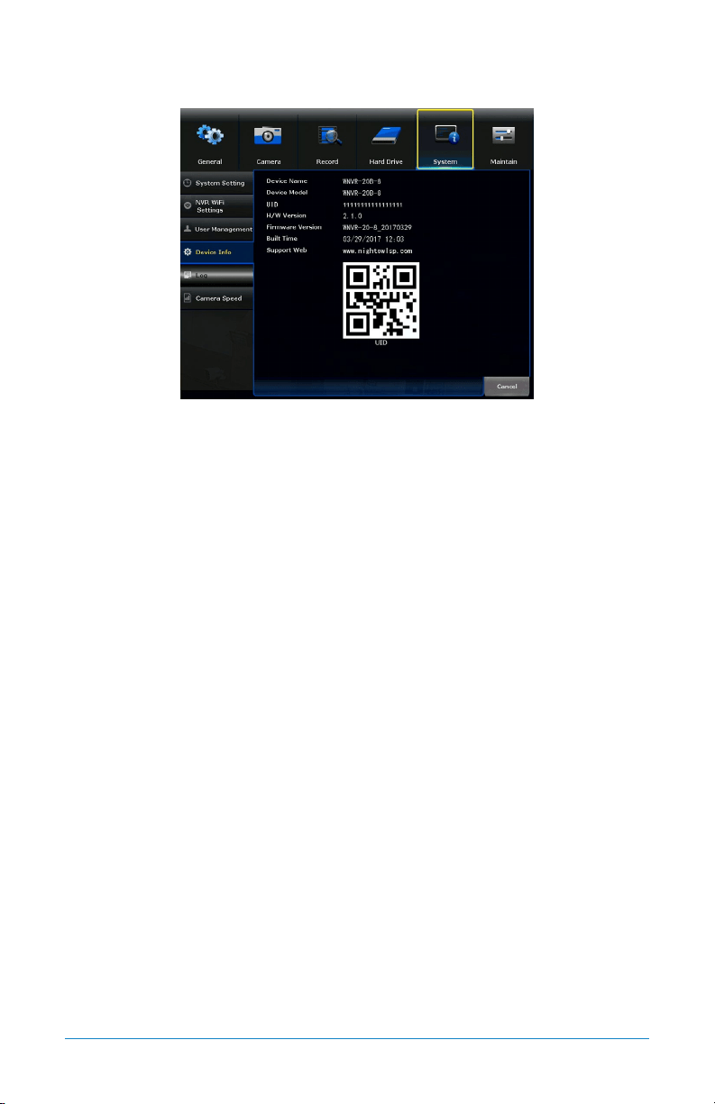
7.5.4 Device Info
Device Name: Create a unique device name for easy reference.
Device Model: Displays your NVR model number.
UID: Unique Device ID number that identifies your NVR.
Hardware Version: The current hardware version of you NVR.
Firmware Version: The current firmware version of your NVR.
Built Time: The date and release time for the current firmware.
Support Web: Night Owl support site web address.
QR Code: QR code that represents the UID number of the NVR. You can scan this
when performing a QR code setup to add this NVR to the Night Owl X App.
64 WNVR Series User’s Manual
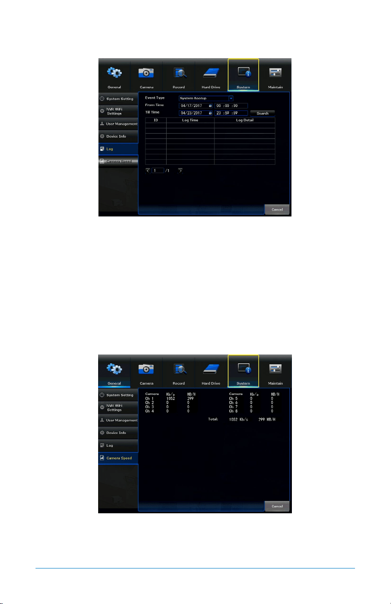
7.5.5 Log
Event Type: Select the type of event log you would like to Search for. Each choice
corresponds to an action or event that was triggered and noted within the system.
From Time: The date and time to start the search.
Till Time: The date and time to finish the search.
Search: Performs a search of the logs. All items found will appear in the table.
Table: Lists all the events found under your search parameter.
7.5.6 Camera Speed
Camera: Displays the amount of bandwidth used by each camera in real-time in
Kb/s and MB/H.
65Chapter 7: Menus and Settings
7.6 Maintain
The Maintain menu will allow access to the Sys Maintenance, Firmware Update
and Factory Default submenus. From these submenus, it will be possible manage
the settings for these categories.
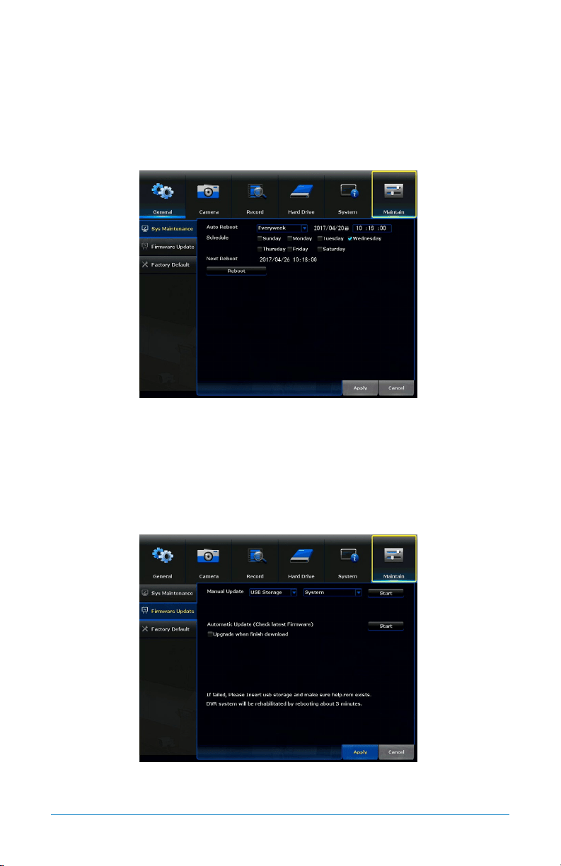
7.6.1 Sys Maintenance
Auto Reboot: Determine how often an auto reboot will occur.
Schedule: Schedule the reboot frequency.
Next Reboot: Shows the date and time of the next reboot.
Reboot: Manually reboot the NVR.
7.6.2 Firmware Update
Manual Update: Manually update the NVR firmware.
Start: Begin the manual update using the chosen method.
66 WNVR Series User’s Manual
Automatic Update: Will check for the latest firmware online. Requires an
Internet connection.
Upgrade when finish download: The system will install the firmware after
it is downloaded.
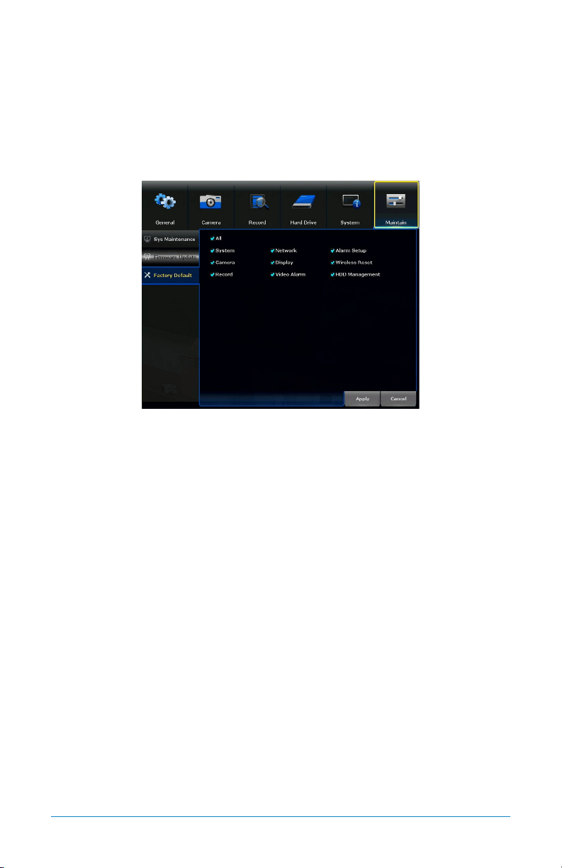
7.6.3 Firmware Default
Features: By default, All is selected. However, you can deselect those features you
do not want restored to Factory Default. Select Apply to restore.

67Chapter 8: Glossary
CHAPTER 8
GLOSSARY

68 WNVR Series User’s Manual
Chapter 8: Glossary
DDNS: Dynamic Domain Naming System. Method for automatically updating
hostnames, address or other information like a URL on a given name server.
DHCP: Dynamic Host Configuration Protocol. A network protocol that allows a
server to automatically assign a device and IP address.
IP: Internet Protocol. Protocol for standard communications across the Internet.
ISP: Internet Service Provider. An organization that provides services for accessing
or using the Internet.
PIR: Passive Infrared. Heat-based sensors eliminate most false alarms and only
delivers alerts when people, animals or vehicles are detected.
SMTP: Simple Mail Transfer Protocol. Standards used for email transmission.
UPS: Uninterrupted Power Supply. Device used to keep the NVR and cameras
powered when the main power supply is lost or disconnected.

69Chapter 9: Warranty
CHAPTER 9
WARRANTY

70 WNVR Series User’s Manual
Chapter 9: Warranty
NIGHT OWL, LLC (‘Night Owl”) provides the following warranty to the original retail
purchaser only (the “Purchaser”) with respect to this product (the “Product”):
For a period of one (1) year after the date of sale, the Product shall be free
from manufacturing defects in material and workmanship. In the event that
the Product is defective, the Purchaser must return the Product at Purchaser’s
cost with the original proof of purchase receipt. In its sole discretion, Night Owl
will either repair or replace the Product at no additional cost to the Purchaser.
Any replacement Product (or parts) will be covered by the same warranty as the
original Product through the expiration date of the original warranty period.
Exclusions
This warranty does not apply to the following parts or upon the following events:
1. Bulbs, LEDs and batteries.
2. The Product was not used or installed in the manner described in the
installation instructions.
3. Negligent use of the Product or misuse or abuse of the Product.
4. Electrical short circuits or power surges.
5. Use of replacement parts not supplied by Night Owl.
6. Product is either tampered with, modified or repaired by another
service provider.
7. Product has not been maintained in accordance.
8. Accident, fire, flood or other acts of God.
9. Failure to use Night Owl approved accessories.
10. Defects or damages arising by use of the Produce in other than normal
conditions (including normal atmospheric, moisture and humidity conditions).
Except as otherwise prohibited by law, this warranty is in lieu of other warranties,
express or implied and Night Owl neither assumes no authorizes any person to
assume for it any other obligation or liability in connection with the sale or service
of the Product.

71Chapter 9: Warranty
In no event shall Night Owl be liable for any special or consequential damages
arising from the use of the Product or arising from the malfunctioning or non-
functioning of the Product or for any delay in the performance of this warranty due
to any cause beyond its control. This warranty shall not apply to installation or
the removal and re-installation of products after repair.
Night Owl does not make any claims or warranties of any kind whatsoever
regarding the Product’s potential, ability or effectiveness to prevent, minimize
or in any way affect personal or property damage or injury. Night Owl is not
responsible for any personal damage, loss or theft related to the Product or to its
use for any harm, whether physical or mental related thereto. Any and all claims
or statements, whether written or verbal, by salespeople, retailers, dealers or
distributors to the contrary are not authorized by Night Owl and do not affect this
provision of this warranty.
Returns Under this Warranty
In order to obtain service, please make sure that you have registered
your product on-line no later than thirty (30) days after purchase at
www.NightOwlSP.com in the warranty registration section or in any other
manner described in the instructions.
Disclaimer
Certain uses, publication and/or distribution of video/audio recordings from security
cameras and/or audio devices are prohibited or restricted by federal, state and local
laws. When enabling and/or using audio recording features with your hidden security
camera, be sure to comply with the laws in your country, state and locality.
Mac and Mac OS X are registered trademarks of Apple Inc. Windows, Windows XP,
Windows Vista, Windows 7, Windows 8 and Windows 10 are registered trademarks
of Microsoft Corporation in the United States and/or other countries.

72 WNVR Series User’s Manual
CHAPTER 10
TROUBLESHOOTING

73Chapter 10: Troubleshooting
Chapter 10: Troubleshooting
If a problem occurs, you may be able to easily correct it yourself. The following
table describes some common issues and their most likely solutions. Please refer
to the table before calling technical support.
Error Possible Causes Solutions
System is not receiving power or
is not powering up.
Cable from power adapter is
loose or is unplugged.
1. Confirm that all cables are
connected correctly.
2. Confirm that the power
adapter is securely connected
to the back of the unit.
Cables are connected, but
system is not receiving sufficient
power.
1. Confirm that the system is
powered ON (LED indicators
on the front should be ON).
2. If the unit is connected
through a power bar or surge
protector, try bypassing the
bar and connecting the power
directly to the wall outlet.
3. Confirm that there is power at
the outlet.
4. Connecting the power cable
to another outlet.
5. Test the outlet with another
plugged device (such as a
phone charger).
Hard drive is not detected by
the system.
Hard drive cables are loose or
not properly connected.
Remove the cover and check
that the hard drive cables are
firmly connected.
There is no hard drive in the
system.
Open the cover and install a
3.5" SATA hard drive.
Hard drive is full (0%) and the
unit is no longer recording.
Overwrite is not enabled.
Login to your NVR, select the
Hard Drive menu and ensure
Overwrite is checked.
Mouse not detected by system.
Mouse cable is not firmly
connected to the system.
Firmly connect the mouse cable
to the USB Mouse port on the
front panel.
Mouse is not connected to the
system.
System needs to be reset.
Power off the system
(disconnect power cable). Firmly
connect a USB mouse to the
USB Mouse port on the front
panel of the system. Reconnect
the power cable to the DC 19V
port on the real panel.

74 WNVR Series User’s Manual
Error Possible Causes Solutions
The image on the NVR appears,
but does not have sound.
Audio cables are loose or have
been disconnected.
Check the AUDIO connection to
the NVR.
Audio channels are disable.
Right click in Live View and
ensure Volume is enabled.
Volume on external speakers
(not included) is low or off.
Increase volume on external
speakers (not included).
A “whirring” noise is coming
from the system.
Fan is active.
The noise means the exhaust
fan is working normal.
The system beeps at startup. The beep at startup is normal.
The system beeps during motion
detection.
Motion detection is enabled and
the alarm buzzer is activated.
Go to the General Menu > Video
Alarm, select the channel and
turn Audible Warning to off.

75Chapter 11: User Information
CHAPTER 11
USER INFORMATION

76 WNVR Series User’s Manual
Chapter 11: User Information
Be sure to write down all the important information below and place it in a
secure location.
General NVR Information
Admin Password: ________________________________________________________
User Password: __________________________________________________________
Component Model Number: _______________________________________________
NOTE: Your Component Model Number can be found by accessing the System menu
and Device Info submenu.
Internet Login Information
NOTE: This information can be found within the General Menu tab under
Network in your NVR’s Main Menu.
Mac Address: ___________________________________________________________
Web Port: ______________________________________________________________
IP Address: _____________________________________________________________
Subnet Mask: ___________________________________________________________
Gateway: _______________________________________________________________
Preferred DNS: __________________________________________________________

www.NightOwlSP.com
EMAIL
Sales Support
Sales@NightOwlSP.com
Technical Support
Support@NightOwlSP.com
PHONE (English, Spanish & French)
Sales/ Technical Support
1.866.390.1303
Live Chat 24/7, 365 days a year
WEBSITE
24/7 Product Support
• How-To Videos
• Manuals
• Firmware Updates
CONTACT US
iPhone, iPad, Mac and Mac OS X are registered trademarks of Apple Inc.
Windows, Windows XP, Windows Vista, Windows 7, Windows 8 and
Windows 10 are registered trademarks of Microsoft Corporation in the
United States and/or other countries.
Rev 170515