Loading ...
Loading ...
Loading ...
REPAIR
Front-To.Rear Mower Adjustment
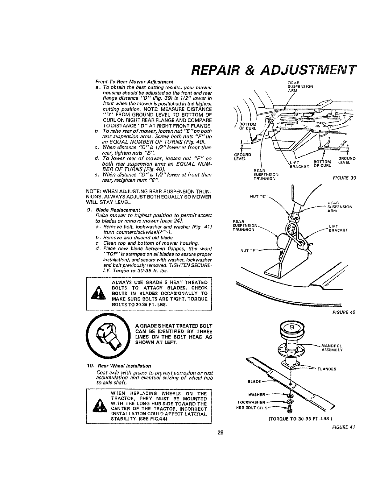
a To obtain the best cutting results, your mower
housing should be adjusted So the front and rear
flange distance "'D" (Fig, 391 is 1/2"" lower in
front when the mower is positioned in the highest
cutting position. NOTE: MEASURE DISTANCE
"D °" FROM GROUND LEVEL TO BOTTOM OF
CURL ON RIGHT REAR FLANGE AND COMPARE
TO DISTANCE "D" AT RIGHT FRONT FLANGE
b. To raise rear of mower, Ioosannut "E"on both
rear suspension arms. Screw bdth nuts "F" up
an EQUAL NUMBER OF TURNS (Fig. 40).
c. When distance "D" is I/2" lower at front than
rear, tighten nuts "E."_
do To lower rear of mower, loosen nut "F" on
both rear suspension arms an EQUAL NUM-
BER OF TURNS (Fig_ 40).
e. When distance "D" is l /2" lower at front than
rear, retighten nuts "E"
& ADJUSTMENT
"_LrFT BOTTOM
6RACKET OF CURL
$
GROUND
LEVEL
REAR
SUSPENSION
TR_JNN_ON FIGURE 39
NOTE: WHEN ADJUSTING REAR SUSPENSION TRUN-
NfONS, ALWAYS ADJUST BOTH EQUALLY SO MOWER
WILL STAY LEVEL.
9, Blade Replacement
Raise mower to highest position to permit access
to blades or remove moor (page 24)..
a. Remove bolt, lockwasher end washer (Fig_ 41)
(turn counterclockwiselii_-_)o
b. Remove and discard old blade..
c Clean top and bottom of mower housings.
d Place new blade between flanges, (the word
"TOP" is stamped on afl blades to assure proper
installation), and secure with washer, lockwasher
and bolt previously removed. TIGHTEN SECURE-
LY. Torqbe to 30-35 ft.. Ibs.
A
ALWAYS USE GRADE 5 HEAT TREATED
BOLTS TO ATTACH BLADES, CHECK
BOLTS tN BLADES OCCASIONALLY TO
MAKE SURE BOLTS ARE TIGHT. TORQUE
BOLTS TO 30-35 FT, LBS,
A GRADE 5 HEAT TREATED BOLT
CAN BE IDENTIFIED BY THREE
LINES ON THE BOLT HEAD AS
SHOWN AT LEFT°
10, Roar Wheel Installation
Coat axle with grease to prevent corrosion or rust
accumulation and eventual seizing of wheel hub
to axle shaft.
WHEN REPLACING WHEELS ON THE
TRACTOR, THEY MUST BE MOUNTED
WITH THE LONG HUB SIDE TOWARD THE
CENTER OF THE TRACTOR. INCORRECT
INSTALLATION COULD AFFECT LATERAL
STABILITY_ {SEE FIG°44L
REAR
SUSPI
TRUNNION
LIFT
NUT "F
FIGURE 40
25
FIGURE 41
Loading ...
Loading ...
Loading ...