Loading ...
Loading ...
Loading ...
9_
Mower Ddve Belt Adjustment
Your tractor has been manufactured with the
ability to m_djust the mower drive belt to pro-
vide you with longer belt life.
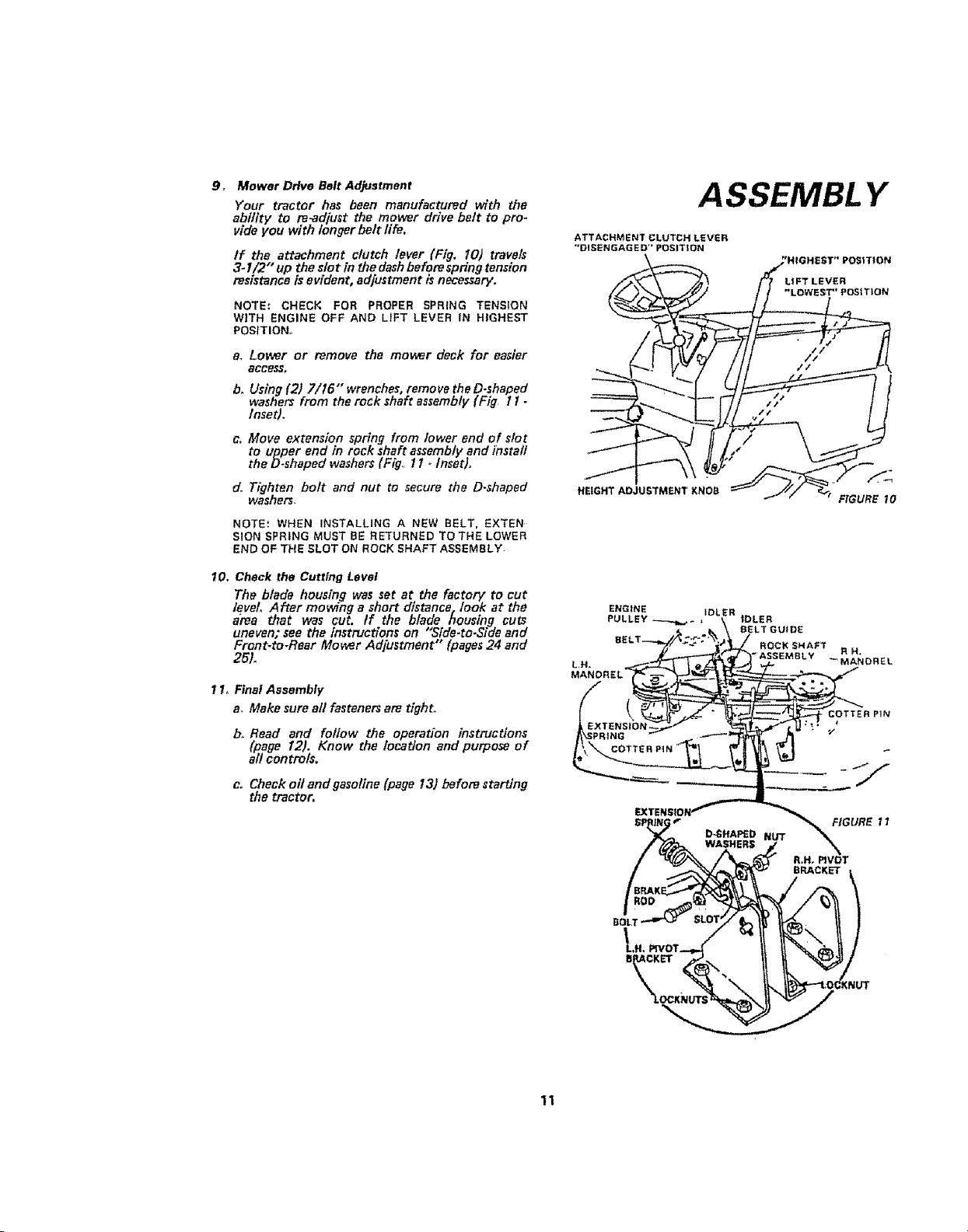
If the attachment clutch lever (Fig, 10) travels
3- I/2" up the slot in the dash before spring tension
resistanca is evident, adjustment is necessary.
NOTE.* CHECK FOR PROPER SPRING TENSION
WITH ENGINE OFF AND L_FT LEVER IN HIGHEST
POSITION,,
a, Lower or remove the mower deck for easier
access,
b_ Using (2) 7/t6"' wrenches, remove the D-shaped
washers from the rock shaft assembly (Fig I i -
Inset).
e_ Move extension spring from lower end of slot
to upper end in rock thaft assembly and install
the Doshaped washers (Fig., 1t oInset},
do Tighten bolt and nut to secure the D.shaped
washer;,
NOTE', WHEN INSTALLING A NEW BELT. EXTEN
SION SPRING MUST BE RETURNED TO THE LOWER
END OF THE SLOT ON ROCK SHAFT ASSEMBLY
10. Check the Cutting Level
The blade housing was set at the factorF to cut
level, After mowing a short distance, look at the
area that was cut, If the blade housing cuts
uneven; see the instructions on "Side.to,Side and
Front-to-Rear Mower Ad[ustment" (pages 24 and
25L
1Io FinalAssembly
a, Make sureall fasteners are tight,
b_ Read and follow the operation instructions
(page 12). Know the location and purpose of
al! contmls.
c. Check oll and gasoline (page 13) before starting
the tractor,
ASSEMBL Y
ATTACHMENT CLUTCH LEVER
"DIS£NGAGE D" POSITION
HEIGHT ADJUSTMENT KNOB
FIGURE t0
ENGINE IDLER
PULLEY
FIGURE t I
R.H_ PIVOT
BRACKET
BOLT
11
Loading ...
Loading ...
Loading ...