Loading ...
Loading ...
Loading ...
I WARNING I
To avoid electrical shock which can cause severe
personal injury or death, green ground wire must remain
attached to hinge.
4. Unplug top hinge wire connectors. Do not remove
green ground wire from hinge (Freezer door ice and
water dispensing units only). Remove top hinge
screws. Carefully lift and remove top hinges.
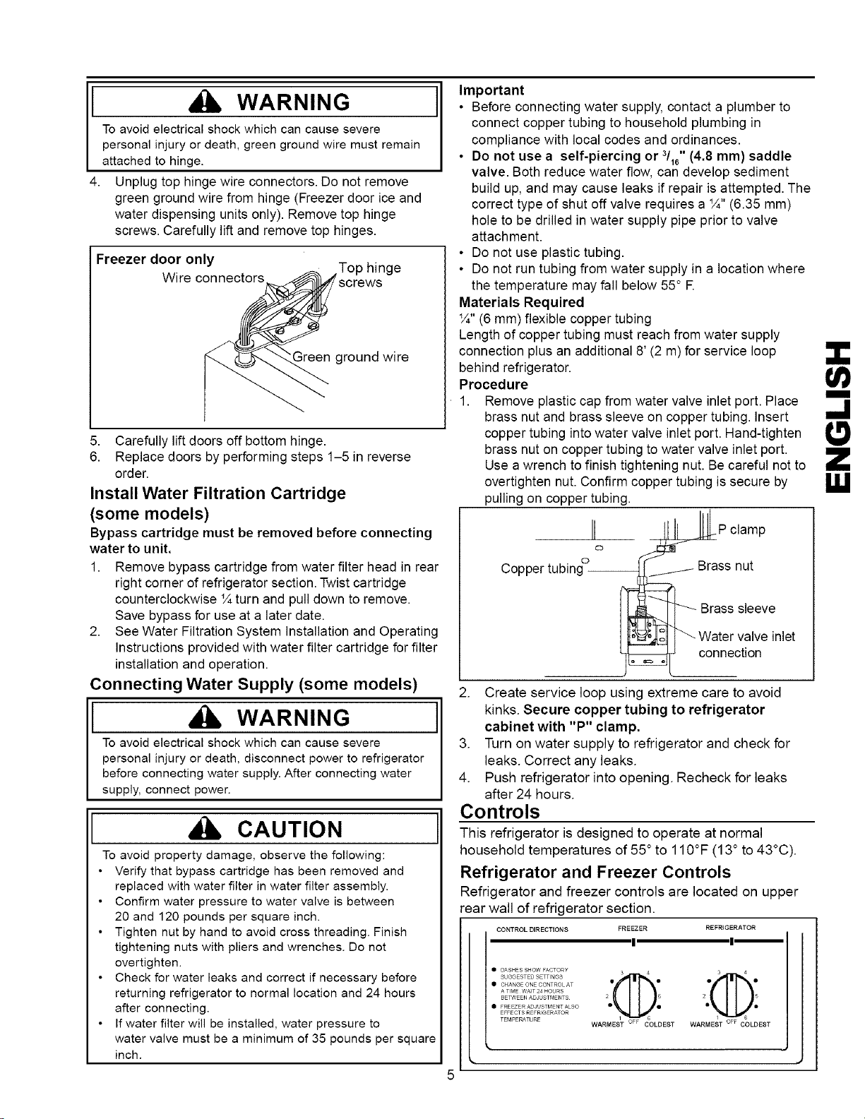
Freezer door only
Wire connectors
Top hinge
..qreenground wire
5. Carefully lift doors off bottom hinge.
6. Replace doors by performing steps 1-5 in reverse
order.
Install Water Filtration Cartridge
(some models)
Bypass cartridge must be removed before connecting
water to unit.
1. Remove bypass cartridge from water filter head in rear
right corner of refrigerator section. Twist cartridge
counterclockwise IAturn and pull down to remove.
Save bypass for use at a later date.
2. See Water Filtration System Installation and Operating
Instructions provided with water filter cartridge for filter
installation and operation.
Connecting Water Supply (some models)
I WARNING I
To avoid electricalshock which can cause severe
personal injuryor death, disconnect power to refrigerator
before connecting water supply.Afterconnecting water
supply, connect power.
CAUTION
To avoid property damage, observe the following:
• Verify that bypass cartridge has been removed and
replaced with water filter in water filter assembly.
• Confirm water pressure to water valve is between
20 and 120 pounds per square inch.
• Tighten nut by hand to avoid cross threading. Finish
tightening nuts with pliers and wrenches. Do not
overtighten.
• Check for water leaks and correct if necessary before
returning refrigerator to normal location and 24 hours
after connecting.
• If water filter will be installed, water pressure to
water valve must be a minimum of 35 pounds per square
inch.
Important
• Before connecting water supply, contact a plumber to
connect copper tubing to household plumbing in
compliance with local codes and ordinances.
• Do not use a self-piercing or 3/16"(4.8 mm) saddle
valve. Both reduce water flow, can develop sediment
build up, and may cause leaks if repair is attempted. The
correct type of shut off valve requires a 1/#,(6.35 mm)
hole to be drilled in water supply pipe prior to valve
attachment.
• Do not use plastic tubing.
• Do not run tubing from water supply in a location where
the temperature may fall below 55° R
Materials Required
1/#,(6 mm) flexible copper tubing
Length of copper tubing must reach from water supply
connection plus an additional 8' (2 m) for service loop
behind refrigerator.
Procedure
1. Remove plastic cap from water valve inlet port. Place
brass nut and brass sleeve on copper tubing. Insert
copper tubing into water valve inlet port. Hand-tighten
brass nut on copper tubing to water valve inlet port.
Use a wrench to finish tightening nut. Be careful not to
overtighten nut. Confirm copper tubing is secure by
pulling on copper tubing.
II I,III Pc,amp
Copper tubing° Brass nut
] _ I _ Water valve inlet
_ connection
2. Create service loop using extreme care to avoid
kinks. Secure copper tubing to refrigerator
cabinet with "P" clamp.
3. Turn on water supply to refrigerator and check for
leaks. Correct any leaks.
4. Push refrigerator into opening. Recheck for leaks
after 24 hours.
Controls
This refrigerator is designed to operate at normal
household temperatures of 55° to 110°F (13° to 43°C).
Refrigerator and Freezer Controls
Refrigerator and freezer controls are located on upper
rear wall of refrigerator section.
CONTROL DIRECTIONS FREEZER REFRIGERATOR
! !
• DASHES SHOW FACTORY 3 4 3 4
• CHANGE ONE CONTROL AT • •
A TIME WAIT 24 HOURS
2 5
BETWEEN ADJ STMSNTS 2 5
• FREEZER AD J STMSNT ALSO
EFFECTS RE FR GSRATOR
TEMPERATURE WA R EST I,NARMEST OFF COLDES T
m
!;1
I,!,1
5
Loading ...
Loading ...
Loading ...