Loading ...
Loading ...
Loading ...
ELECTRICAL/PIPING INSTALLATION
Method #3: Cable Splicing for #8 Wire Cable
(Splice to #10 or smaller wire ONLY)
1. Remove 3/8" insulation from end of motor pigtail leads
and from drop cable leads.
2. Place heat shrink tubing over motor pigtail leads.
3. Insert leads into butt connector and crimp with crimping
tool. Pull leads to check connection.
4. Center tubing over butt connector and apply heat with a
propane torch (a match or lighter wifl not supply enough
hea0.
NOTICE: Keep torch moving; too much concentrated
heat in one place will ruin tubing and may damage wires.
5. When tubing begins to shdnk, increase concentration of
heat at center of tube. As center of tube collapses on wire,
work heat out to each end until entire tube is collapsed
tight around wire.
Heat-shrink tubing
/
Wire Ends Ready to Splice;
Strip 1/2" back for crimp-type connectors
!
Wire S#iced (Crimped)
NOTICE: If there is a chance that pump can overpump well,
install a Pump Guard (Stock No. 2721) to prevent running
pump dry.
ff depth of well and the distance to the water level in the
well are not known, See page 4. The pump should not be
set closer than 5 feet from the bottom of the well and should
be submerged 15 to 20 feet below the draw down water
level. If the draw down water level is not known, set the
pump 5 feet from the bottom of the well.
Install centering guides (purchase from Sears - Stock No.
2724). These are used to keep pump, pipe and electrical
cable centered in the well.
NOTICE: Install a torque protector (available locally) to pro-
tect pipe from twisting damage due to motor starting.
To prevent dropping anything into the well, keep the top of
the casing covered.
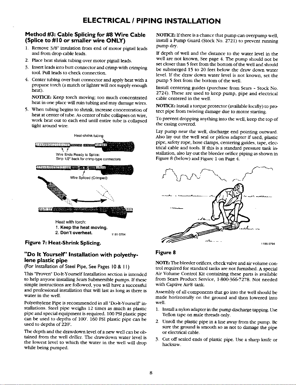
Lay pump near the well, discharge end pointing outward.
Also lay out the well seal or pitless adapter if used, plastic
pipe, safety rope, hose clamps, centering guides, tape, elec-
trical cable and tools. If this is a standard pressure tank in-
stallation, also lay out the bleeder orifice piping as shown in
Figure 8 (below) and Figure 1 on Page 4.
Heat with torch:
1. Keep the heat moving.
2. Don't overheat.
Figure 7: Heat-Shrink Splicing.
1181 0794
"Do It Yourself" Installation with polyethy-
lene plastic pipe
(For Installationof Steel Pipe, See Pages 10 & II)
This "Proven" Do-h-Yourself Installation section is intended
to help anyone installing Sears Submersible pumps. If these
simple instructions are followed, you will have a successful
and professional installation that will last as long as there is
water in the well
Polyethylene Pipe is recoumaended in all "Dolt-YourselF' in-
stallations. Steel pipe weighs 12 times as much as plastic
pipe and special equipment is required. 100 PSI plastic pipe
can be used to depths of 100'. 160 PSI plastic pipe can be
used to depths of 220'.
The depth and the drawdown level of a new well can be ob-
tained from the well driller. The drawdown water level is
the lowest level to which the water in the well will drop
while being pumped.
1186 0794
Figure 8
NOTE: The bleeder orifices, check valve and air volume con-
trol required for standard tanks are not furnished. A special
Air Volume Control Kit containing these parts is available
from Sears Product Service, 1-800-366-7278. Not needed
with Captive Air@ tank.
Assembly of all components that go into the well should be
made horizontally on the ground and then lowered into
well.
1. Install a nylon adapter in the pump discharge tapping. Use
Teflon tape on male threads only.
2. Unroll the plastic pipe in a line away from the pump. Be
sure the ground is smooth so as not to damage the pipe
or electrical cable.
3. Cut off sealed ends of plastic pipe. Use a sharp knife or
hacksaw.
Loading ...
Loading ...
Loading ...