Loading ...
Loading ...
Loading ...
INSTALLATION
17. Develop the well - See "Well Development and Pump
Test".
18. Before piping up a Captive Air@ Tank, be certain air pres-
sure in tank is the same as the cut-in pressure of the pres-
sure switch. For additional information, see instructions
on tank or in the tank owners manual. Complete piping
to pressure tank.
Installation with Steel Pipe
1. Read the "Do It Yourself Installation with Plastic
Pipe" section first. Information on the following items
will be found there:
Depth to water Well Depth
Drawdown Proper Pump Setting
Centering Guides Electrical Cable Splicing
Testing the Pump Pressure Tanks
2. Screw a length of galvauized pipe into discharge of pump.
3. With the pump and pipe in vertical position, tape cable
to pipe just above and below the splice connections.
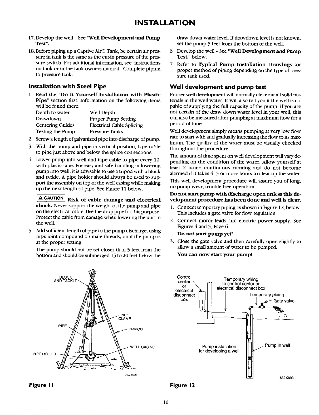
4. Lower pump into well and tape cable to pipe every 10'
with plastic tape. For easy and safe handling in lowering
pump into well, it is advisable to use a tripod with a block
and tackle. A pipe holder shotfld always be used to sup-
port the assembly on top of the well casing while making
up the next length of pipe. See Figure 11 below.
IA CAUTION] Risk of cable damage and electrical
q
shock. Never support the weight of the pump and pipe
on the electrical cable. Use the drop pipe for this purpose.
Protect the cable from damage when lowering the unit in
the well.
5. Add sufficient length of pipe to tbe pump discharge, using
pipe joint compound on male threads, until the pump is
at the proper setting.
The pump should not be set closer than 5 feet from the
bottom and should be submerged 15 to 20 feet below the
draw down water level. If drawdown level is not known,
set the pump 5 feet from the bottom of the well.
6. Develop the well - See "Well Development and Pump
Test," below.
7. Refer to Typical Pump Installation Drawings for
proper method of piping depending on the type of pres-
sure tank used.
Well development and pump test
Proper well development will normally clear out all solid ma-
terials in the well water. It will also tell you if the well is ca-
pable of supplying the full capacity of the pump. If you are
not certain of the draw down water level in your well, this
can also be measured after pumping at maximum flow for a
period of time.
Well development simply means pumping at very low flow
rate to start with and gradually increasing the flow to its max-
imum. The quality of the water must be visually checked
throughout the procedure.
The amount of time spent on well development will vary de-
pending on the condition of the water. Allow yourself at
least 2 hours continuous running and do not become
alarmed if it takes 4, 5 or more hours to clear up the water.
This well development procedure will assure you of long,
no-pump wear, trouble free operation.
Do not start pump with discharge open unless this de-
velopment procedure has been done and well is clear.
1. Connect temporarypiping as shown in Figure 12, below.
This includes a gate valve for flow regulation.
2. Connect motor leads and electric power supply. See
Figures 4 and 5, Page 6.
Do not start pump yet!
3. Close the gate valve and then carefully open slightly to
allow a small amount of water to be pumped.
You can now start your putnp!
BLOCK
PIPE
Control
or
electrical
disconnect
box
Temporary wiring
to control center or
electrical disconnect box
Temporary piping
Gate valve
m _
Pump installation
for developing a well
in well
Figure II
724 0993
Figure 12
6890993
10
Loading ...
Loading ...
Loading ...