Loading ...
Loading ...
Loading ...
INSTALLATION
Standard Air Tank Installation
Pitless Adapter
El_p_ _ctrical Pipe Tee
Service with Plug
Conduit or
Galvanized Sleeve
ipe
WellSeal
Pitless ToTank (Purchase ,
_'_ --'- Locally)
-- Check
Valve
2 Ft.
Bleeder_-
Oriticies
Sanitary Well Seal
TO Tank ---_
3 Ft, _ Plastic Pipe
Adapter
Clamps*
2 Ft,
3 Ft.
\ Galvanized
Pipe up
through well
seal
Cable
Ny_n
Tape
• Plastic pipe adapter, pipe
clamps, and torque arrester
used only withplastic pipe.
Cable sa__ Centenng
Splices Guide
Torque
Arrester
(Pumha
Looal,y,IJll
Plastic r_
Pipe
Adapter* t 178 0794
Pump
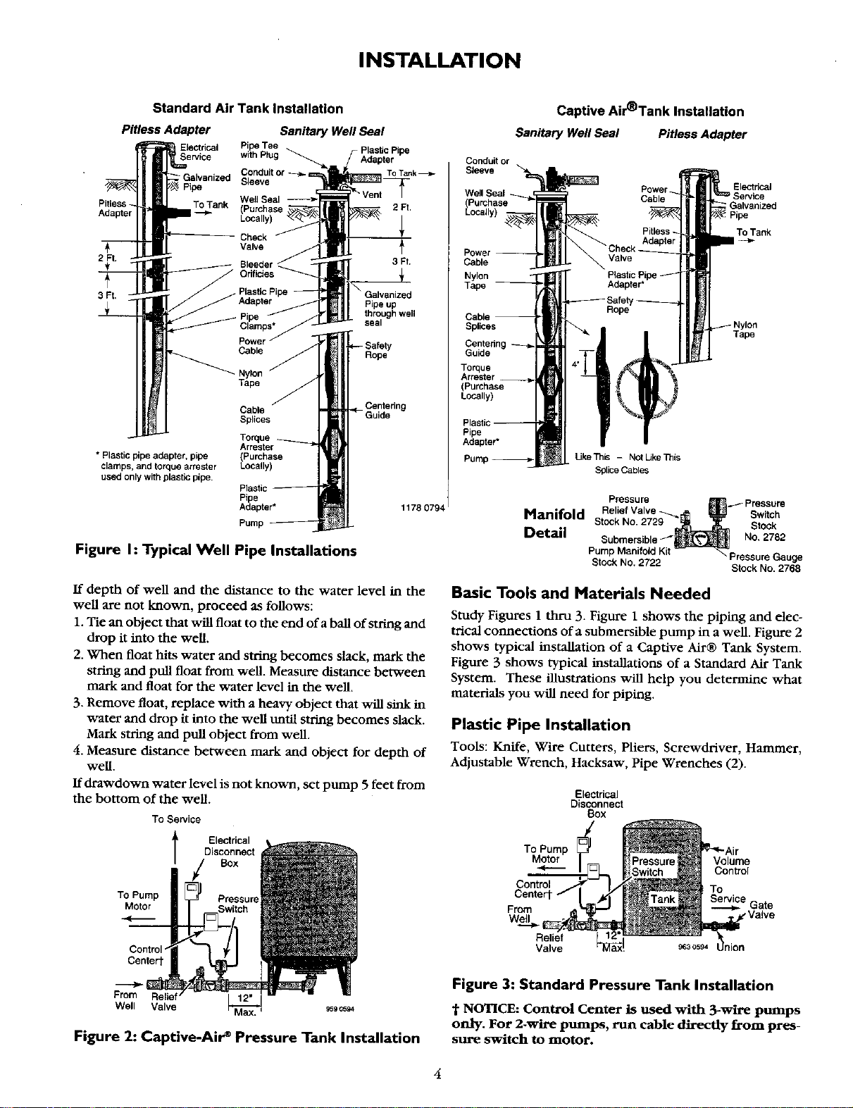
Figure I: Typical Well Pipe Installations
If depth of well and the distance to the water level in the
well are not known, proceed as follows:
1. Tie an object that will float to the end of a ball of string and
drop it into the well.
2. When float hits water and string becomes slack, mark the
string and pull float from well. Measure distance between
mark and float for the water level in the well.
3. Remove float, replace with a heavy object that will sink in
water and drop it into the well until string becomes slack.
Mark string and pull object from well.
4. Measure distance between mark and object for depth of
well.
If drawdown water level is not known, set pump 5 feet from
the bottom of the well.
To Sewice
l Ele_dcal
Disconnect
Box
To Pump Pressure
Motor
Control"
Centert
From
Well Valve
Figure 2: Captive-Air* Pressure Tank Installation
Captive Air'Tank Installation
SanitaryWellSeal PitlessAdapter
Conduit or
Sleeve
Well Seal
(Purchase
Locally)
Power
Cable
Nylon
Tape --
Electrical
; Galvanized
To Tank
Splices
Tape
Torque
Arrester
(Purchase
Locally)
Pipe
Adapter•
UkeTh_ - NotUkeTnis
Splice Cables
Manifold
Detail
Pressure
• ._ Pressure
Relief Valve _ Sw tch
Stock No. 2729 Stock
Submersible/" No, 2782
P_cP Marlin2 dKit Pressure Gauge
• Stock No. 2768
Basic Tools and Materials Needed
Study Figures 1 thru 3. Figure 1 shows the piping and elec-
trical connections of a submersible pump in a well. Figure 2
shows typical installation of a Captive Air® Tank System•
Figure 3 shows typical installations of a Standard Air Tank
System• These illustrations will help you determine what
materials you will need for piping.
Plastic Pipe Installation
Tools: Knife, Wire Cutters, Pliers, Screwdriver, Hammer,
Adjustable Wrench, Hacksaw, Pipe Wrenches (2).
Electrical
Disconnect
(3ox
To Pump
Motor
Volume
Control
Control
Centert
From e Gate
Wel_l ,Valve
Relief
Valve ss3c594
Figure 3: Standard Pressure Tank Installation
"i"NOTICE: Control Center is used with 3-wire pumps
only. For 2-wire pumps, run cable directly from pres-
sure switch to motor.
4
Loading ...
Loading ...
Loading ...