Loading ...
Loading ...
Loading ...
INSTALLATION
Materials: Plastic Pipe and Fittings (as required to complete
job); Teflon Tape (DO NOT use pipe joint compound on
plastic fittings); Centering Guides - Stock No. 2724.
Galvanized Steel Pipe Installation
Tools: Knife, Wire Cutters, Pliers, Screwdriver, Hammer,
Adjustable Wrench, Hacksaw, Pipe Wrenches (2), Pipe
Cutting and Threading Tools.
Materials: Galvanized Pipe and Fittings (as required to com-
plete job); Pipe Joint Compound or Teflon Tape; Centering
Guides - Stock No. 2724.
Safety Pressure Relief Valve Stock No. 2729
For your protection, install this pressure relief valve.
Purchase from your local Sears Store.
This relief valve is designed to protect home water systems
from excessive pressure. It is factory preset to start relieving
pressure at 75 PSI (pounds per square inch). Use only on
home water systems with pumps listed in this Owners
Manual.
1. For maximum protection, locate valve within 2 ft. of the
pressure tank.
2. Install valve directly in pipe tee. Do not use any reducers
or pipe extensions. Tee must be located in main pump
supply line to tank. See diagram Page 4.
3. Protect relief valve from freezing, dirt, and any other pos-
sible damage that would cause the valve not to function.
4. Long lengths of pipe or hose connected to the relief valve
discharge port can limit the amount of water and pressure
that can be relieved, ff necessary to pipe away from relief
valve, use minimum 1-1/4" plastic pipe.
5. Protect everything in the immediate area of the relief valve
from water damage in the event the relief valve operates.
Gauge
A Pressure Gauge, Stock No. 2768, can be installed. It will
indicate the pressure at which pump starts and stops and
any pressure in between.
The Motor
The motor is water filled type, and is ready to run as received.
Pressure Switch
Install an automatic pressure switch (Stock No. 2782) set to
start pump at 40 lbs. pressure and stop pump when the sys-
tem pressure reaches 60 lbs. See Figures 2 and 3, Page 4.
Tank
The tank serves two functions. It provides a reservoir of
water, which can be drawn off through the house fixture.
The tank maintains a cushion of air under pressure. When
tank pressure falls far enough, pump will start.
Two types of tanks are available: Captive Air® and Standard.
The Air Volume Control (AVC) maintains the cushion of air
in Standard Tanks. No Air Volume Control is needed with a
Captive Air® Tank.
Air Volume Control
A device mounted on a standard tank in order to keep
enough air in the tank to prevent waterlogging the tank.
Operating a water system with no air cushion in the pres-
sure tank can cause water hammer, rapid pump cycling, and
damage to the system.
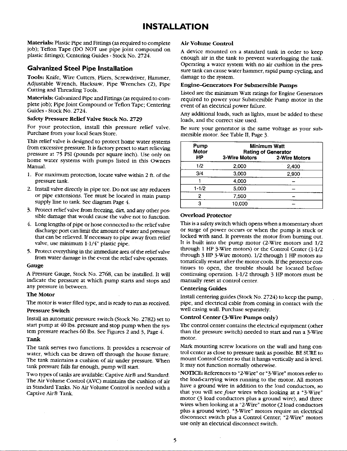
Engine--Generators For Submersible Pumps
Listed are the minimum Watt ratings for Engine Generators
required to power your Submersible Pump motor in the
event of an electrical power failure.
Any additional loads, such as lights, must be added to these
loads, and the correct size used.
Be sure your generator is the same voltage as your sub-
mersible motor. See Table II, Page 3.
Pump Minimum Watt
Motor Rating of Generator
HP 3-Wire Motors 2-Wire Motors
1/2 2,000 2,400
3/4 3,000 2,900
1 4,000 -
1-1/2 5,000 -
2 7,500 -
3 10,000 -
Overload Protector
This is a safety switch which opens when a momentary short
or surge of power occurs or when the pump is stuck or
locked with sand. It prevents the motor from burning out.
It is built into the pump motor (2-Wire motors and 1/2
through 1 HP 3-Wire motors) or the Control Center (1-1/2
through 3 HP 3-Wire motors). 1/2 through 1 HP motors au-
tomatleally restart after the motor cools. If the protector con-
tinues to open, the trouble should be located before
continuing operation. 1-1/2 through 3 HP motors must be
manually reset at control center.
Centering Guides
Install centering guides (Stock No. 2724) to keep the pump,
pipe, and electrical cable from coming in contact with the
well casing wall. Purchase separately.
Control Center (3-Wire Pumps only)
The control center contains the electrical equipment (other
than the pressure switch) needed to start and run a 3-Wire
motor.
Mark mounting screw locations on the wall and hang con-
trol center as close to pressure tank as possible. BE SURE to
mount Control Center so that it hangs vertically and is level.
It may not function normally otherwise.
NOTICE: References to "2-Wire" or "3-Wire" motors refer to
the load-carrying wires running to the motor. All motors
have a ground wire in addition to the load conductors, so
that you will see four wires when looking at a "3-Wire"
motor (3 load conductors plus a ground wire), and three
wires when looking at a _2-Wire" motor (2 load conductors
plus a ground wire). "3-Wire" motors require an electrical
disconnect switch plus a Control Center; "2-Wire" motors
use only an electrical disconnect switch.
Loading ...
Loading ...
Loading ...