Loading ...
Loading ...
Loading ...
Indoor Unit Wiring
4. Clamp down the cable with the cable clamp.
5. Insulate unused wires with electrical tape.
Keep them away from any electrical or metal
parts.
6. Reinstall the cover of the electric control box.
1. Prepare the cable for connecon.
a. Using wire strippers, strip the rubber jacket
from both ends of the signal cable to reveal
about 5.9” (15cm) of the wire.
b.
Strip the insulaon from the ends of the
wires.
c. Using a wire crimper, crimp the u-lugs to
the ends of the wires.
WARNING
ISOLATE THE POWER SUPPLY LEADS AND
COMMUNICATION LEADS BY THE STRAIN
RELIF AND KEEP POWER SUPPLY LEADS
AWAY FROM COMMUNICATION LEADS.
RISK OF ELECTRIC SHOCK CAN CAUSE
INJURY OR DEATH. DISCONNECT ALL
REMOTE ELECTRIC POWER SUPPLIES
BEFORE SERVICING.
WARNING
2. Open the front panel of the indoor unit. Using
a screwdriver,remove the cover of the electric
control box on your indoor unit.
3. Thread the power cable and the signal cable
through the wire outlet.
4. Connect the u-lugs to the terminals.
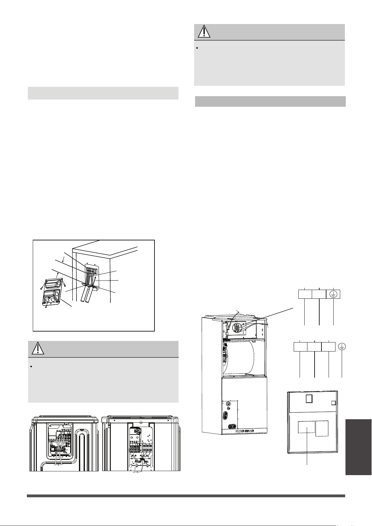
Wiring diagram
1. Remove the wire cover from the unit by
loosening the 3 screws.
2. Dismount caps on the conduit panel.
3. Temperarily mount the conduit tubes(not
included) on the conduit panel.
4. Properly connect both the power supply and
low voltage lines to the corresponding
terminals on the terminal block.
5. Ground the unit in accordance with local
switchs.
6. Be sure to size each wire allowing several
inches longer than the required length for
wiring.
7. Use lock nuts to secure the conduit tubes.
In North America
G
Wire Cover
Over 1.57in.(40mm)
Terminal block
Conduit panel
Connecting cable
Power supply cord
Please select the appropriate through-hole according
to the diameter of the wire.
Outdoor Unit A Outdoor Unit B
Class2 wire
Power
wire
Match the wire colors/labels with the labels on
the terminal block. Firmly screw the u-lug of
each wire to its corresponding terminal. Refer
to the Serial Number and Wiring Diagram
located on the cover of the electric control box.
L1
TO POWER SOURCE
L2
L1
TO OUTDOOR
L2 S
Page 39
Wiring
Loading ...
Loading ...
Loading ...