PRO.FORM°8 3 5 Q F
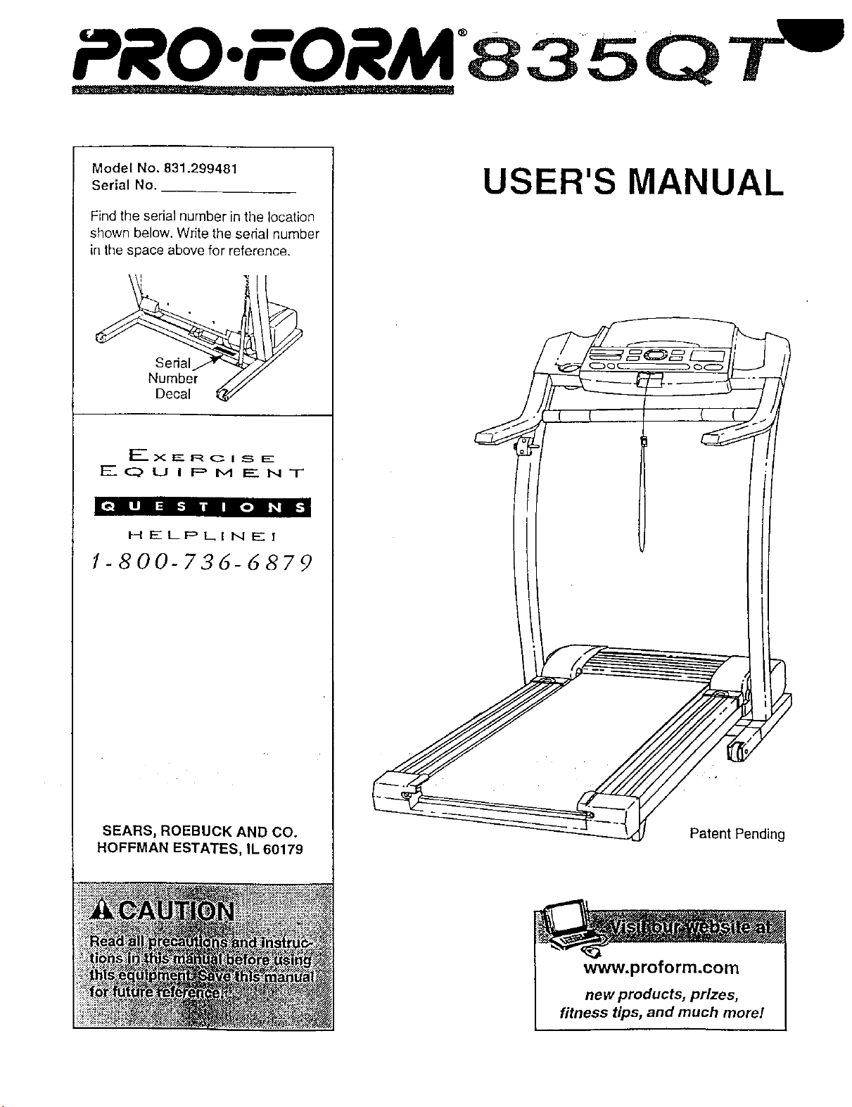
Model No. 831.299481
Serial No. __
Find the serial number in the location
shown below. Write the serial number
in the space above for reference.
EQUIPMENT
|l,,R g| :i-| n |e| _ gi-1
HELPLINE!
1-800-736-6879
SEARS, ROEBUCK AND CO.
HOFFMAN ESTATES, IL 60179
USER'S MANUAL
Patent Pending
ii!!i
www.proform.com
new products, prizes,
fitness tips, and much more/

PRO'FORM 8 3 5 Q T
¥
TABLE OF CONTENTS
IMPORTANT PRECAUTIONS ................................................................. 3
BEFORE YOU BEGIN ....................................................................... 5
ASSEMBLY ............................................................................... 6
OPERATION AND ADJUSTMENT ............................................................. 8
HOW TO FOLD AND MOVE THE TREADMILL .................................................. 19
TROUBLE-SHOOTING .................................................................. ._,.20
CONDITIONING GUIDELINES ............................................................... 22
PART LIST ............................................................................... 23
ORDERING REPLACEMENT PARTS .................................................. Back Cover
FULL 90-DAY WARRANTY ........................................................... Back Cover
Note: An EXPLODED DRAWING is attached in the center of this manual.
2

IMPORTANT PRECAUTIONS
!
23. AIW ......
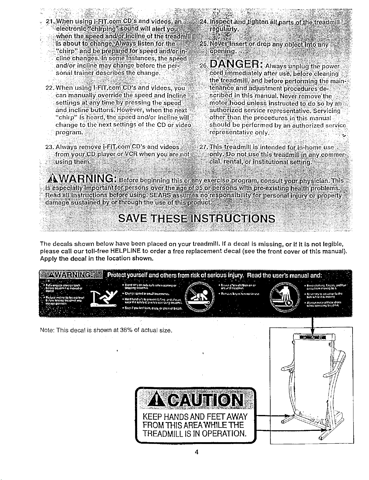
The decals shown below have been placed on your treadmill. If a decal is missing, or if it is not legible,
please call our toll-free HELPLINE to order a free replacement decal (see the front cover of this manual).
Apply the decal in the location shown.
Note: This decal is shown at 38% of actual size.
KEEP HANDsAND FEETAWAY
FROMTHIS AREAWH1LETHE
TREADMILLIS INOPERATION.
BEFORE YOU BEGIN
Thank you for selecting the revolutionary PROFORM =
835QT treadmill. The 835QT treadmill combines ad-
vanced technology with innovative design to helpyou
get the most from your exercise program in the conve-
nience and privacy of your home. And when you'renot
exercising, the unique 835QT can be folded up, requir-
ingless than half the floor space of other treadmills.
For your benefit, read this manual carefully before
using the treadmill• Ifyou have additional questions,
please call our toll-free HELPLINE at 1-800-736-6879,
Monday through Saturday, 7 a.m. until7 p.m. Central
Time (excluding holidays). To help usassist you,
please note the product model number and sedal num-
ber before calling. The model number ofthe treadmill
is 831.299481. The sedal number can be found on a
decal attached to the treadmill (see the front cover of
this manual for the location).
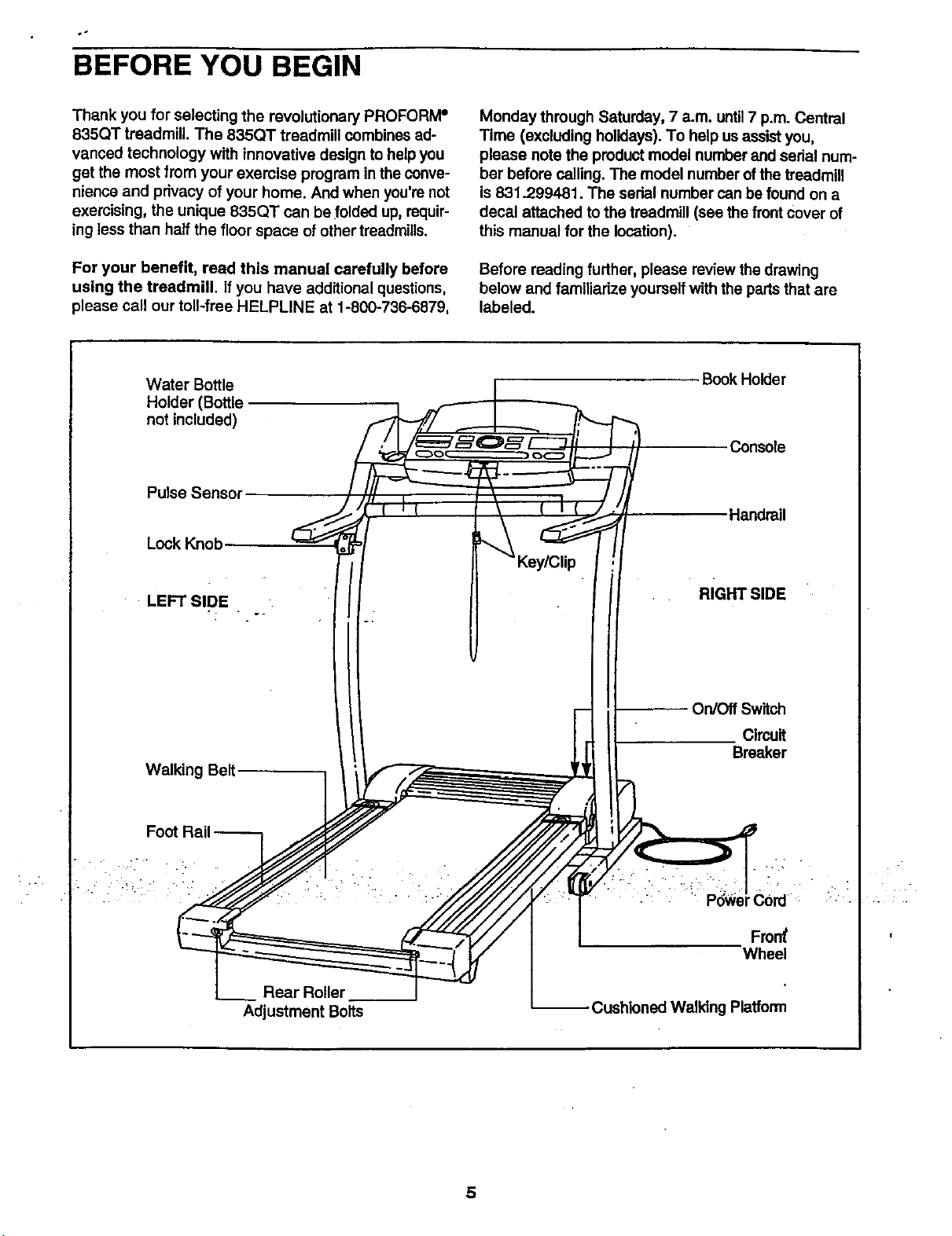
Before reading further, please review the drawing
below and familiarize yourself with the parts that are
labeled.
Water Bottle
Holder (Bottle
not included)
Pulse Sensor
Lock Knob
LEFT SIDE
Walking Belt
Rear Roller
Adjustment Bolts
Book Holder
•Console
Handrail
RIGHT SIDE
On/Off Switch
Clmuit
Breaker
Fron_
Wheel
-- Cushioned Walking Platform
5
ASSEMBLY
Assembly requires two people. Set the treadmill in a cleared area and remove all packing matedals. Do not
dispose of the packing materials untilassembly is completed. Assembly requires your own PhUlips screw-
driver (I_E]======_, wire cutters _;_, and rubber mallet D==:::::=_.
Note: The underside of the treadmill walking belt is coated with high-performance lubricant. During shipping, a
small amount of lubricant may be transferred to the top of the walking belt or the shipping carton• This is a normal
condition and does not affect treadmill performance. If there is lubricant on top of the walking belt, simply wipe off
the lubricant with a soft cloth and a mild, non-abrasive cleaner.
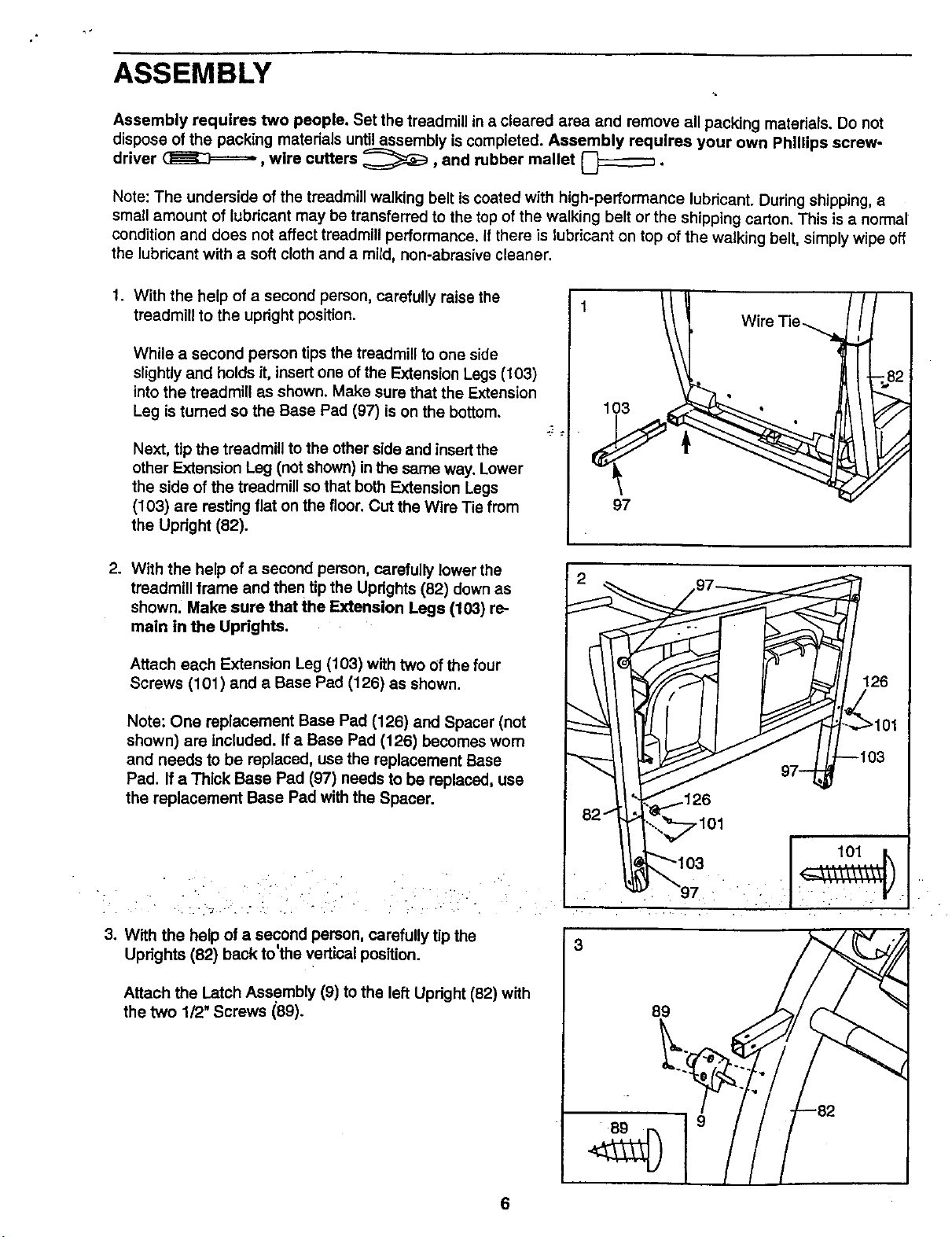
.
With the help of a second person, carefully raise the
treadmill to the upright position.
While a second person tips the treadmill to one side
slightly and holds it, insertone of the Extension Legs (103)
into the treadmill as shown. Make sure that the Extension
Leg is turned so the Base Pad (97) is on the bottom.
Next, tip the treadmill to the other side and insertthe
other Extension Leg (not shown) in the same way. Lower
the side of the treadmill so that both Extension Legs
(103) are resting flat on the floor• Cut the Wire Tie from
the Updght (82).
1
lO3
97
Wire Tie ....,_
.
With the help of a second person, carefully lower the
treadmill frame and then tip the Uprights (82) down as
shown. Make sure that the Extension Legs (103) re-
main in the Uprights.
Attach each Extension Leg (103) with two of the four
Screws (101) and a Base Pad (126) as shown.
Note: One replacement Base Pad (126) and Spacer (not
shown) are included. If a Base Pad (126) becomes wom
and needs to be replaced, use the replacement Base
Pad. If a Thick Base Pad (97) needs to be replaced, use
the replacement Base Pad with the Spacer.
3. With the help of a second person, carefully tip the
back to the vertical position.Updghts (82) ' ' ""
Attach the Latch Assembly (9) to the left Upright (82) with
the two 1/2" Screws (89).
3
.101
89
6
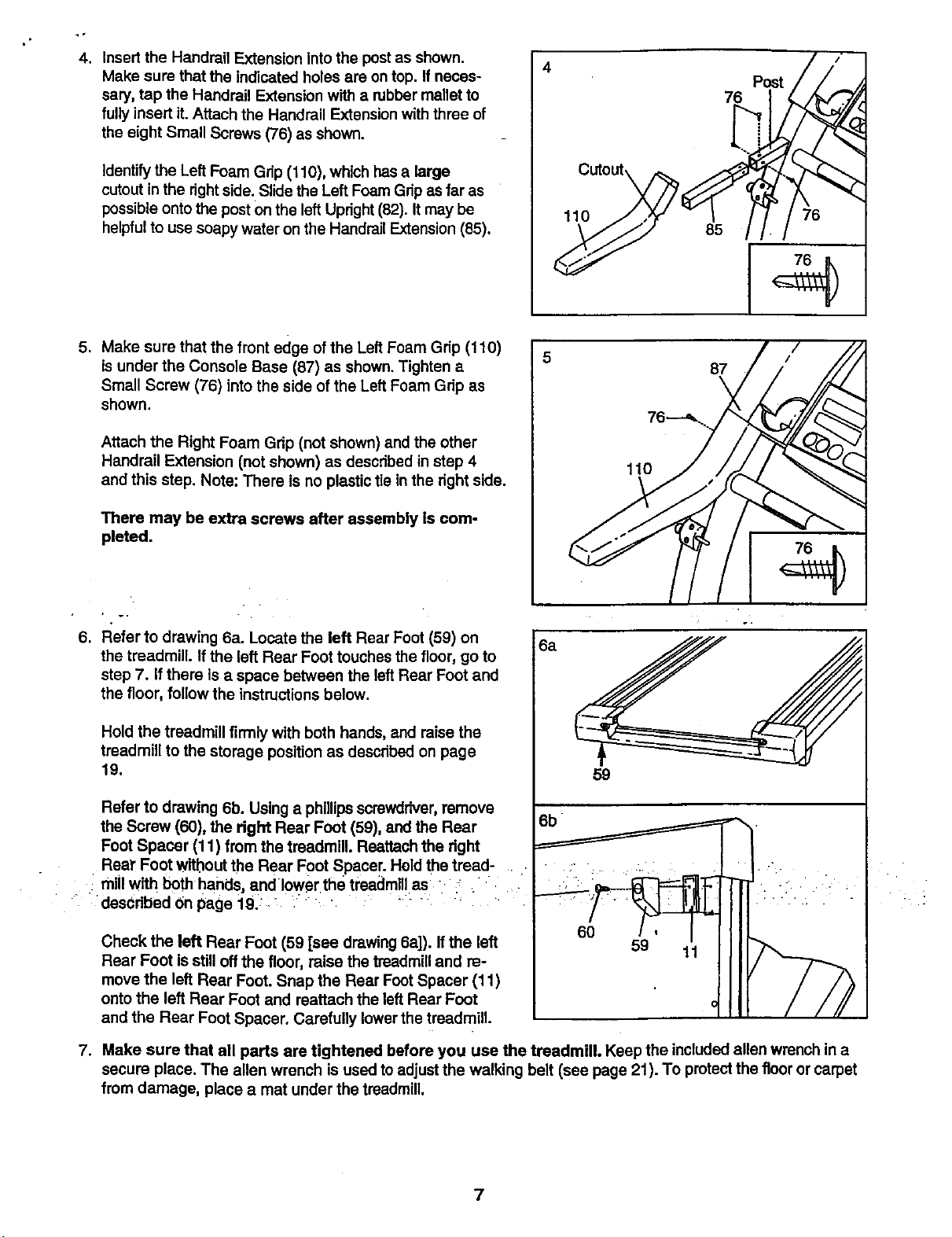
4. Insert the Handrail Extension into the postas shown.
Make sure that the indicated holes are on top. If neces-
sary, tap the Handrail Extension with a robber mallet to
fully insert it. Attach the Handrail Extension with three of
the eight Small Screws (76) as shown.
Identifythe Left Foam Grip (110), which hasa large
cutout in the rightside. Slide the Left Foam Grip as far as
possibleonto the post Onthe left Upright(82). It may be
helpfulto use soapy water on the Handrail Extension(85).
4 Post/i,
5. Make sure that the front edge ofthe Left Foam Grip (110)
is under the Console Base (87) as shown. Tighten a
Small Screw (76) into the side of the Left Foam Grip as
shown.
Attach the Right Foam Grip (not shown) and the other
Handrail Extension (not shown) as described in step 4
and this step. Note: There is no plastic tie in the right side.
There may be extra screws after assembly is com-
pleted.
6. Refer to drawing 6a. Locate the left Rear Foot (59) on
the treadmill. If the left Rear Foot touches the floor, go to
step 7. Ifthere is a space between the left Rear Foot and
the floor, follow the instructionsbelow.
Hold the treadmill firmly with both hands, and raise the
treadmill to the storage position as described on page
19.
Refer to drawing 6b. Using a phillipsscrewdriver,remove
the Screw (60), the right Rear Foot (59), and the Rear
Foot Spacer (11) from the treadmill; Reattaohthe right
• Rear Foot without the Rear Foot Spacer. Held the tread-
millwith both hands, and lower the treadmillas ;
- described Onpage 19/: : _: " :: _
Check the left Rear Foot (59 [see drawing6a]). If the left
Rear Foot is stilloff the floor, raise the treadmilland re-
move the left Rear Foot. Snap the Rear Foot Spacer (11)
onto the left Rear Foot and reattach the left Rear Foot
and the Rear Foot Spacer. Carefully lowerthe treadmill.
5
6a
87
\
59
_6b •
7. Make sure that all parts are tightened before you use the treadmill. Keep the included allen wrench in a
secure place. The allen wrench is used to adjust the walking belt (see page 21). To protectthe floor or carpet
from damage, place a mat under the treadmill,
7
OPERATION AND ADJUSTMENT
THE PERFORMANT LUBE TM WALKING BELT
Your treadmill features a walking belt coated with
PERFORMANT LUBE TM, a high-performance lubricant.
IMPORTANT: Never apply silicone spray or other
substances to the walking belt or the walking plat-
form. Such substances will deteriorate the walking
belt and cause excessive wear.
HOW TO PLUG IN THE POWER CORD
Your treadmill, like any other type of sophisticated
electronic equipment, can be sedous;y damaged by
sudden voltage changes in your home's power.
Voltage surges, spikes, and noise interference can
result from weather conditions or from other appliances
being tumed on or off. To decrease the possibility of
your treadmill being damaged, always use a surge
suppressor with your treadmill (see drawing 1 at
the right).
To purchase a surge suppressor, see your local
PROFORM dealer or call toll-free 1-800-366-7278
end order part number 146148. Use only a single-
outlet surge suppressor that is UL 1449 listed as a
transient voltage surge suppressor (TVSS). The surge
suppressor must have a UL suppressed voltage rating
of 400 volts or less and a minimum surge dissipation of
450 joules. The surge suppressor must be electrically
rated for 120 volts AC and 15 amps.
This product must be grounded, if it sfloufd malfunc-
tion or break down, grounding provides a path of least
resfstance for electric current to reduce the risk of elec-
tric shock. This product is equipped with a cord having
an equipment-grounding conductor and a grounding
plug. Plug the power cord into a surge suppressor,
and plug the surge suppressor into an appropriate
outlet that is properly installed and grounded in
accordance with all local codes and ordinances.
Important: The treadmill is net compatible _ith
GFCl-equipped outlets.
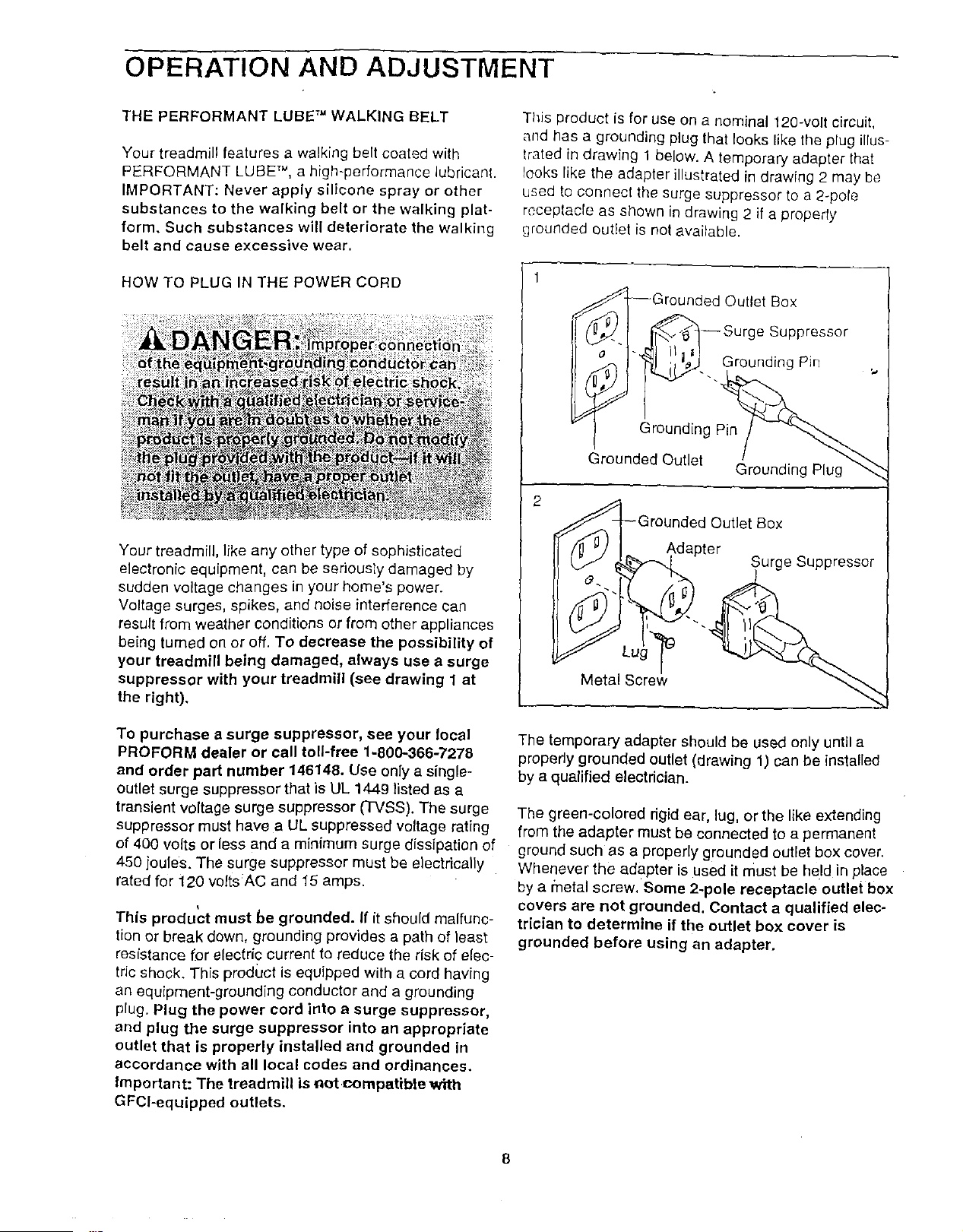
This product is for use on a nominal 120-volt circuit,
and has a grounding plug that looks like the plug illus-
trated in drawing 1 below. A temporary adapter that
looks like the adapter illustrated in drawing 2 may be
used to connect the surge suppressor to a 2-pole
receptacle as shown in drawing 2 if a properly
grounded outlet is not available.
1
,--_-_--Grounded Outlet Box
¢'1 _--Surge Suppressor
'_... Grounding Pin
Grounding Pin
Grounded Outlet
Grounding Plug
2
Metal Screw
d Outlet Box
Adapter
The temporary adapter should be used only until a
properly grounded outlet {drawing 1) can be installed
by a qualified electdcian.
The green-colored dgid ear, lug, or the like extending
from the adapter must be connected to a permanent
ground such as a properly grounded outlet box cover.
Whenever the adapter is used it must be held in place
by a _netal screw, Some 2-pole receptacle outlet box
covers are not grounded. Contact a qualified elec-
trician to determine if the outlet box cover is
grounded before using an adapter.
8
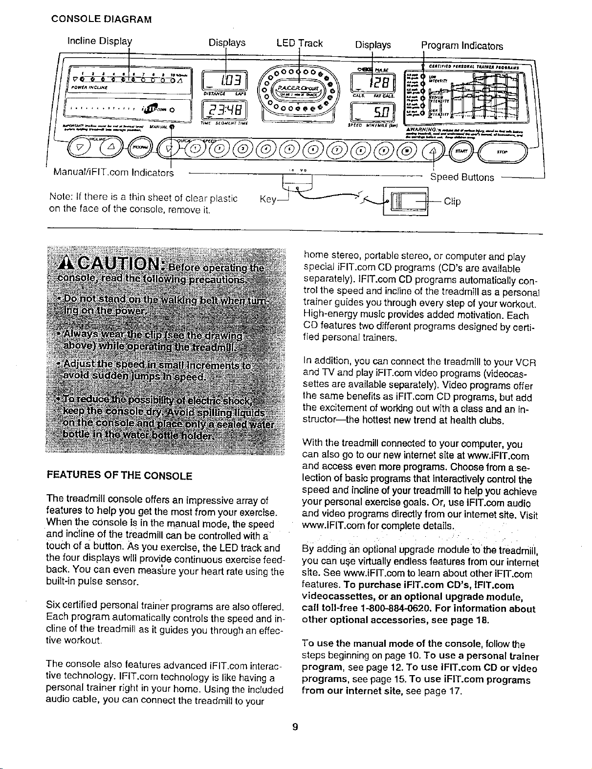
CONSOLE DIAGRAM
Incline Display Displays LED Track Displays Program Indicators
...... •,? -=-=-------
-- _= vo
Manuaf/]FIT.com Indicators ' Speed Buttons
Note: If there is a thin sheet of clear plastic Key Clip
on the face of the console, remove it.
FEATURES OF THE CONSOLE
The treadmill console offers an impressive array of
features to help you get the most from your exercise.
When the console is in the manual mode, the speed
and incline of the treadmill can be controlled with a
touch of 5.button. As you exercise, the LED track and
the four displays will provide continuous exercise feed-
back. You can even meas'ure your heart rate using the
built-in pulse sensor.
Six certified personal trainer programs are also offered.
Each program automatically controls the speed and in-
cline of the treadmill as it guides you through an effec-
tive workout.
The console also features advanced iFIT.com interac-
tive technology. IFIT.com technology is like having a
personal trainer right in your home. Using the included
audio cable, you can connect the treadmill to your
home stereo, portable stereo, or computer and play
special iFIT.com CD programs (CD's are available
separately). IFIT.com CD programs automatically con-
trol the speed and incline of the treadmill as a personal
trainer guides you through every step of your workout.
High-energy music provides added motivation. Each
CD features two different programs designed by certi-
tied persona[ trainers.
In addition, you can connect the treadmill to your VCR
and TV and play iFIT.com video programs (videocas-
settes are available separately). Video programs offer
the same benefits as iFIT,com CD programs, but add
the excitement of working out with a class and an in-
structor-the hottest new trend at health clubs,
With the treadmill connected to your computer, you
can also go to our new internet site at www.iFIT.com
and access even more programs. Choose from a se-
lection of basic programs that interactively control the
speed and incline of your treadmill to help you achieve
your personal exercise goals. Or, use iFIT.com audio
and video programs directly from our intemet site. Visit
www.iFIT.com for complete details.
• . : . .
By adding an optional upgrade moduletothe treadmill,
you can u_e virtually endless features from our intemet
site. See www.iFIT.com to learn about other iFIT.com
features. To purchase iFIT.com CD's, IFIT.com
videocassettes, or an optional upgrade module,
call toll-free 1-800-884-0620. For information about
other optional accessories, see page 18.
To use the manual mode of the console, follow the
steps beginning on page 10. To use a personal trainer
program, see page 12. To use iFIT.com CD or video
programs, see page 15. To use iFIT.com programs
from our internet site, see page 17.
g
HOW TO TURN ON THE POWER
O F'fug _,nthe power cord {see HOW TO PLUG IN
THE POWER CORD on page 8).
la
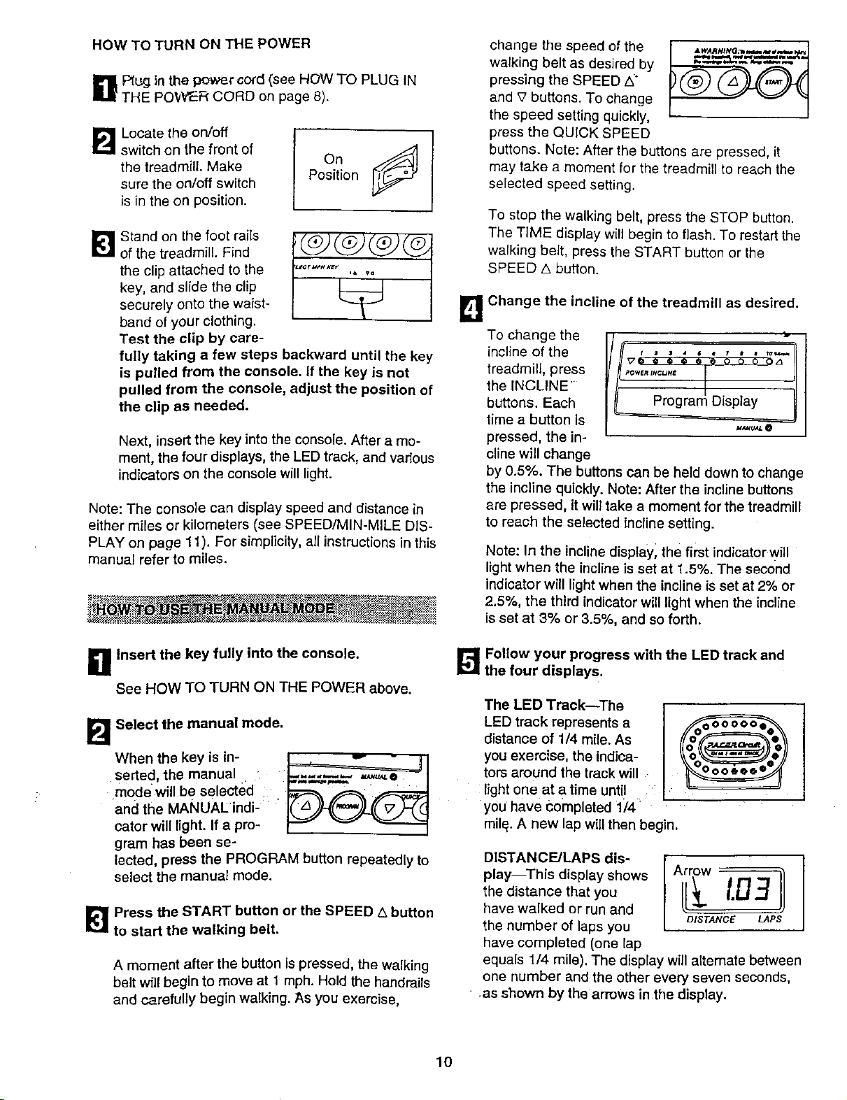
Locate the on/off { [_
switch on the front of
the treadmill. Make On
sure the on/off switch Position
is in the on position.
[]Stand on the foot rails
of the treadmill. Find
the clip attached to the
key, and slide the clip
securely onto the waist-
band of your clothing.
Test the clip by care-
fully taking a few steps backward until the key
is pulled from the console. If the key is not
pulled from the console, adjust the position of
the clip as needed.
Next, insert the key into the console. After a mo-
ment, the four displays, the LED track, and various
indicators on the console will light.
Note: The console can display speed and distance in
either miles or kilometers (see SPEED/MIN-MILE DIS-
PLAY on page 11). For simplicity, all instructions in this
manual refer to miles.
g Insert the key fully into the console.
See HOW TO TURN ON THE POWER above.
B Select the manual mode.
When the key is in- _ - B
serted, the manua _ L--_-__-_,.,___
mode will be selected _"r'_
'and the MANUAL'Indi- 1_,,)_'_('_,)_C(_7_4
catcr will light. If a pro- _ _
gram has been se-
lected, press the PROGRAM button repeatedly to
select the manual mode.
_] Press the START button or the SPEED A button
to start the walking belt.
A moment after the button is pressed, the walking
belt will begin to move at 1 mph. Hold the handrails
and carefully begin walking. As you exercise,
change the speed of the
walking belt as desired by
pressing the SPEED/_"
and _2buttons. To change
the speed setting quickly,
press the QUICK SPEED
buttons. Note: After the buttons are pressed, it
may take a moment for the treadmill to reach the
selected speed setting.
To stop the walking belt, press the STOP button.
The TIME display will begin to flash. To restart the
walking belt, press the START button or the
SPEED/k button.
B Change the incline of the treadmill as desired.
To change the _-
incline of the
treadmill, press
the INCLINE •
buttons. Each
time a button is
pressed, the in-
cline will change
' "" '1....... 1
_7_ o @ _ @ @ o o o oz_
POWER tNCUM£
_ Pr°gra Oisp'a'II
by 0.5%. The buttons can be held down to change
the incline quickly. Note: After the incline buttons
are pressed, itwill take a moment for the treadmill
to reach the selected incline setting.
Note: In the incline displayl the fi_t indicator will
light when the incline is set at 1.5%. The second
indicator will light when the incline is set at 2% or
2.5%, the third indicator will light when the incline
is set at 3% or 3.5%, and so forth.
_ Follow your progress with the LED track and
the four displays.
The LED Track--The
LED track represents a
distance of 1/4 mile. As
you exercise, the indica-
tors around the track will
light one at a time until i
you have Completed 1_'4'
mile. A new lap will then begin.
DISTANCE/LAPS dis-
play--This display shows
the distance that you
have walked or run and
the number of laps you
have completed (one lap
equals 114 mile). The display willaltemate between
one number and the other every seven seconds,
• .as shown by the arrows in the display.
lO
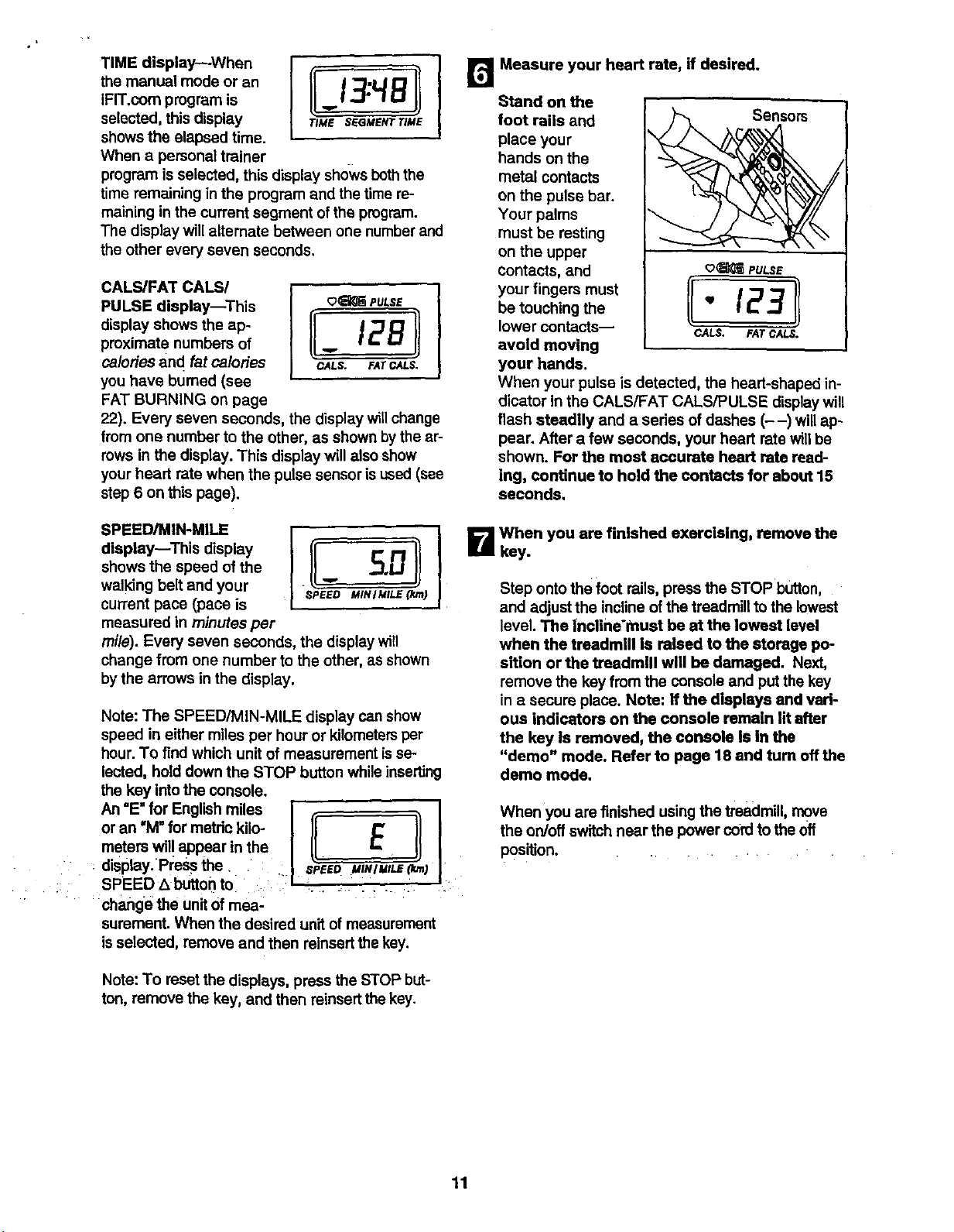
TIME display--When
the manual mode or an
IFIT.com program is
selected, this display
shows the elapsed time.
When a personal trainer
program isselected, this display shows boththe
time remaining in the program and the time re-
maining in the current segment of the program.
The display willalternate between one numberand
the other every seven seconds.
TiME SEGMENT "lIME
CALS/FAT CALS/
PULSE display--This
display shows the ap-
proximate numbers of
ca/odes and fat ca/orJes
you have bumed (see
FAT BURNING on page
_PULSE
CALS. EATCALS.
22). Every seven seconds, the display will change
from one number to the other, as shown by the ar-
rows in the display. This display will also show
your heart rate when the pulse sensor isused (see
step 6 on this page).
SPEED/MIN-MILE l ! r'r_ !
display--This display
shows the speed of the -_.L_
walking belt and your ""
current pace (pace is SPEEDMINIMILE(I(m)
measured in minutes per
mile). Every seven seconds, the display will
change from one number to the other, as shown
by the arrows in the display.
Note: The SPEED/MIN-MILE display can show
speed in either miles per hour or kilometersper
hour. To find which unit of measurement isse-
lected, hold down the STOP button while inserting
the key intothe console.
An =E=for English miles I .- _- _ I
or an "M" for metdo kilo- I I_ E I) I
meters will appear in the I II II I
display. Pl:essthe_ : I _'PEED MINIMILE(k_m)J
:: SPEED LlbUttorl to ii:l i.... _ I
change the unitOfmea-
surement. When the desired unitof measurement
is selected, remove and then reinsert the key.
Note: To reset the displays, press the STOP but-
ton, remove the key, and then reinsert the key.
Measure your heart rate, if desired.
Stand on the
foot rails and Sensors
place your
hands on the
metal contacts
on the pulse bar. _
Your palms
must be resting _.
on the upper
contacts, and o_ PULSE
your fingers must [[ ]l
be touching the ,m / E
lower contacts-- CALS. FAT CALS.
avoid moving
your hands.
When your pulse is detected, the heart-shaped in-
dicator In the CALS/FAT CALS/PULSE displaywill
flash steadily and a series of dashes (--) willap-
pear. After a few seconds, your heart rate will be
shown. For the most accurate heart rata read-
ing, continue to hold the contacts for about 15
seconds.
B When you are finished exercising, remove the
key.
Step onto the foot rails, press the STOP button,
and adjust the incline of the treadmill to the lowest
level. The Incline'must be at the lowest level
when the treadmill is raised to the storage po-
sition or the treadmill will be damaged. Next,
remove the key from the console and put the key
in a secure place. Note: If the displays and vari-
ous indicators on the console remain lit after
the key Is removed, the console Is In the
"demo" mode• Refer to page 18 and turn off the
demo mode.
When you are finished using the treadmill, move
the on/off switch near the power cord to the off
position. ....
11
a Insert the key into the console.
See HOW TO TURN ON THE POWER on page
10.
t]
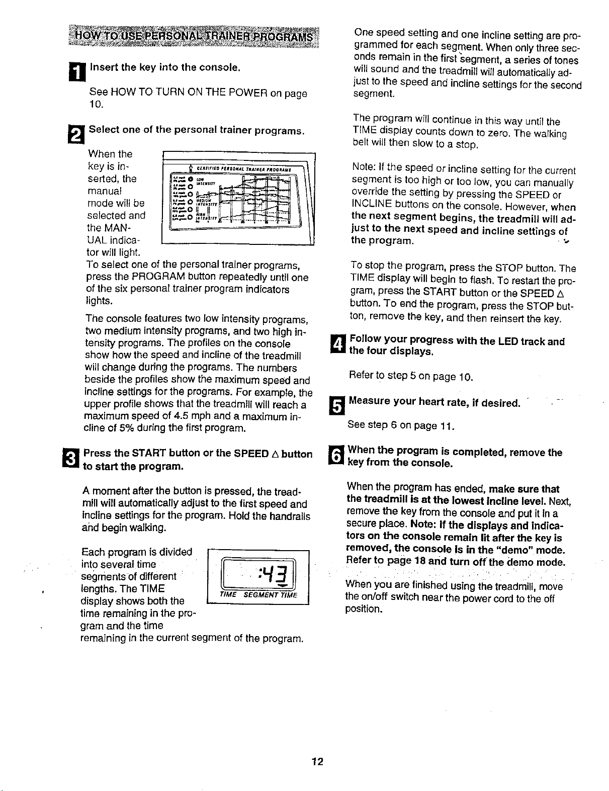
Select one of the personal trainer programs.
When the
key is in-
serted, the
manual
mode wil{ be
selected and
the MAN-
UAL indica-
tor will light.
o=.,. _. I'1P tlI!
=o --
... ^
To select one of the personal trainer programs,
press the PROGRAM button repeatedly until one
of the six personal trainer program indicators
lights.
The console features two low intensity programs,
two medium Intensity programs, and two high in-
tensity programs. The profiles on the console
show how the speed and incline of the treadmill
will change during the programs. The numbers
beside the profiles show the maximum speed and
incline settings for the programs. For example, the
upper profile shows that the treadmill will reach a
maximum speed of 4.5 mph and a maximum in-
cline of 5% during the first program.
I_ Press the START button or the SPEED A button
to start the program.
A moment after the button is pressed, the tread-
mill will automatically adjust to the first speed and
Incline settings for the program. Hold the handrails
and begin walking.
Each program is divided
into Several time
segments of different
lengths. The TIME
display shows both the
time remaining in the pro-
I!..
TIME $EGMr:NT TIME
gram and the time
remaining in the current segment of the program.
One speed setting and one incline setting are pro-
grammed for each segment. When only three sec-
onds remain in the first segment, a series of tones
will sound and the treadmill will automaticalJy ad-
just to the speed and incline settings for the second
segment.
The program will continue in this way until the
TIME display counts down to zero. The walking
belt will then s_ow to a stop.
Note: If the speed or incline setting for the current
segment is too high or too low, you can manually
override the setting by pressing the SPEED or
INCLINE buttons on the console. However, when
the next segment begins, the treadmill will ad-
just to the next speed and incline settings of
the program.
To stop the program, press the STOP button. The
TIME display will begin to flash. To restartthe pro-
gram, press the START button or the SPEED Z_
button. To end the program, press the STOP but-
ton, remove the key, and then reinsert the key.
B Follow your progress with the LED track and
the four displays,
Refer to step 5 on page 10.
_ Measure your heart rate, if desired.
See step 6 on page 11.
r,_ When the program is completed, remove the
key from the console.
When the program has ended, make sure that
the treadmill is at the lowest Incline level. Next,
remove the key from the console and put it In a
secure place. Note: If the displays and indica-
tors on the console remain lit after the key is
removed, the console is in the "demo" mode.
Refer to page 18 and turn off the demo mode.
When you are finished using the treadmill, move
the on/off switch near the power cord to the off
position.
12
To use iFIT.oom CD's, the treadmill must be con-
nected to your portable CD player, portable stereo,
home stereo, or computer with CD player. See pages
13 and 14 for connecting instructions. To use iFIT.com
videoeassettes, the treadmill must be connected to
your VCR. See page 15 for connecting instructions. To
use iFIT.com programs directly from our internet
site, the treadmill must be connected to your home
computer. See page 14 for connecting instructions.
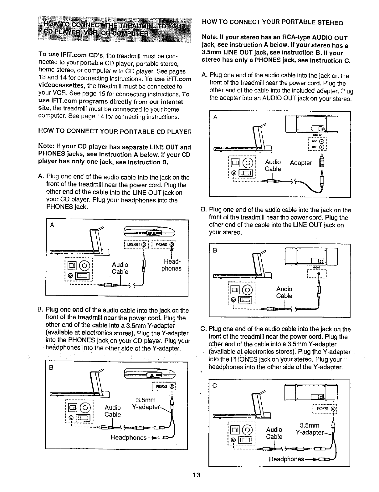
HOW TO CONNECT YOUR PORTABLE CD PLAYER
Note: If your CD player has separate LINE OUT and
PHONES jacks, see instruction A below. If your CD
player has only one jack, see instruction B.
A. Plug one end of the audio cable into the jack on the
front of the treadmill near the power cord. Plug the
other end of the cable into the LINE OUT jack on
your CD player. Plug your headphones into the
PHONES jack.
A
AudZ ;'
! [_-"] @] Cable _ phones
B. Plug one end of the audio cable into the jack on the
front of the treadmill near the power cord. Plug the
other end of the cable into a 3.5mm Y-adapter
(available at electronics stores). Plug the Y-adapter
into the PHONES jack on your CD player. Plug your
headphones into the other side of the Y-adapter
B
1I v
Head_
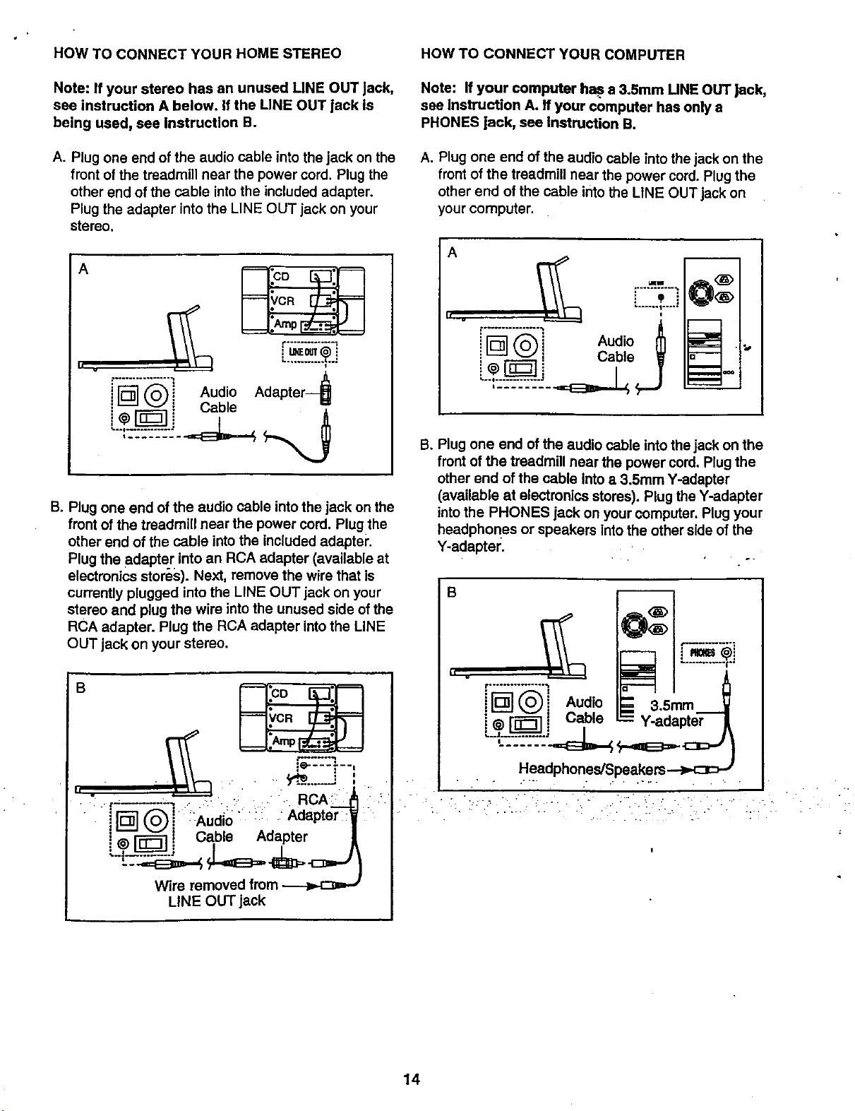
HOW TO CONNECT YOUR PORTABLE STEREO
Note: If your stereo has an RCA-type AUDIO OUT
jack, see instruction A below. If your stereo has a
3.5mm LINE OUT jack, see instruction B. If your
stereo has only a PHONES jack, see instruction C.
A. Plug one end of the audio cable into the jack on the
front of the treadmill near the power cord. Plug the
other end of the cable into the included adapter. Plug
the adapter into an AUDIO OUT jack on your stereo.
,;2C 4i [_1 _ i Audio Adapter
: _ [ Cable
_® I_._J _
B. Plug one end of the audio cable into the jack on the
front of the treadmill near the power cord. Plug the
other end of the cable into the LINE OUT jack on
your stereo.
B
.L
II v
t- ................
i@@ Audio
' Cable
'---_--_--_--_--_,_--_._
C. Plug one end of the audio cable into the jack on the
front of the treadmill near the power cord. Plug the
other end of the cable into a 3.5mm Y-adapter
(available at electronics stores). Plug the Y-adapter
into the PHONES jack on your stereo. Plug your
headphones into the other side of the Y-adapter.
C
_................ 3.5mm
_[_] @ Audio
: _., Y-adapter
--..V
..............cE=L , /
Headphones
13
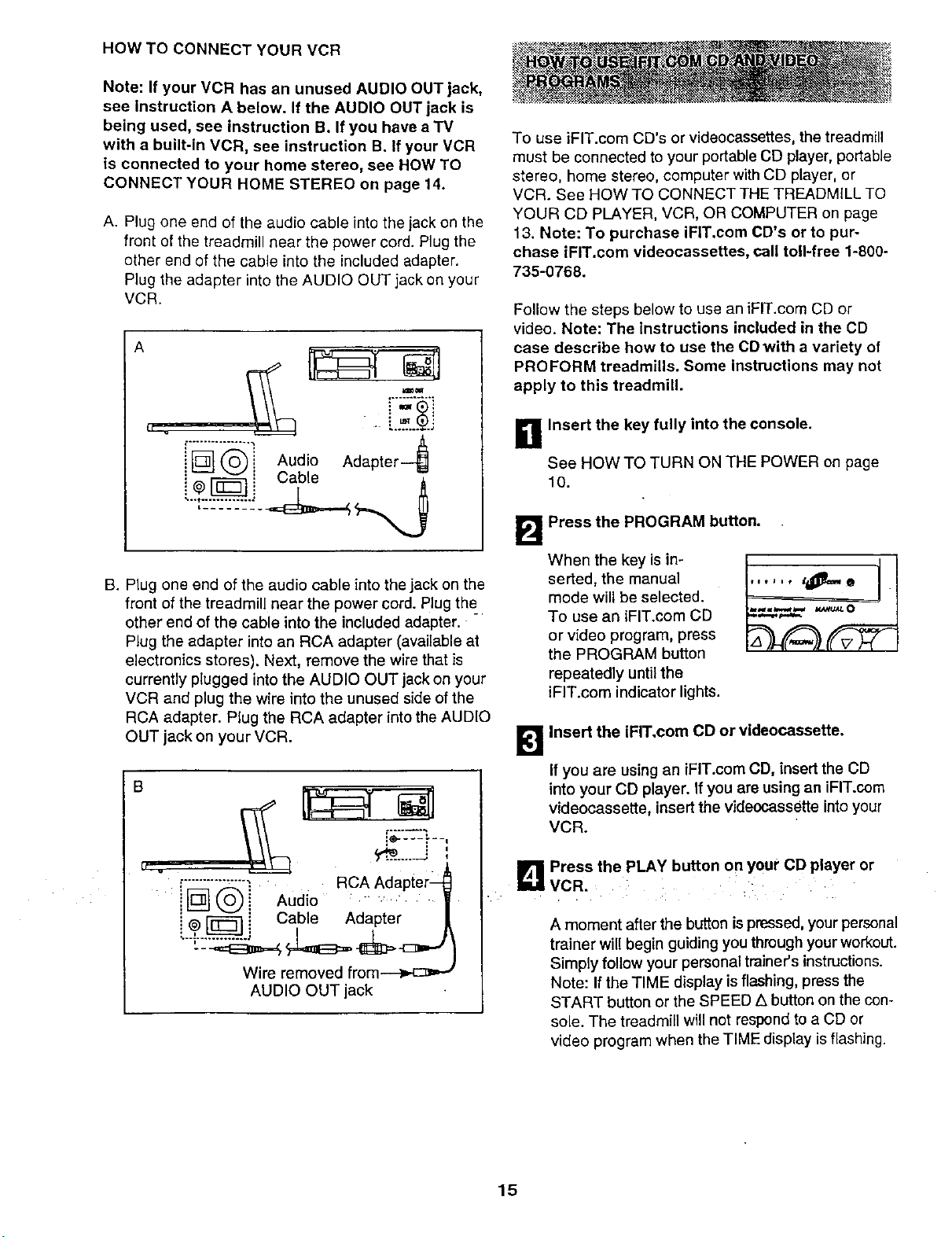
HOW TO CONNECT YOUR HOME STEREO
Note: If your stereo has an unused LINE OUT Jack,
see instruction A below. If the LINE OUT jack is
being used, see Instruction B,
A. Plug one end of the audio cable into the jack on the
front of the treadmill near the power cord. Plug the
other end of the cable into the included adapter,
Plug the adapter into the LINE OUT jack on your
stereo.
A
II v
L .......... ?oJ
"r_]- _i Audio Adapter 4
i_ _ i Cable "_,
4...'Z-_"_"_-_"L"_
B. Plug one end of the audio cable into the jack on the
front of the treadmill near the power cord. Plug the
other end of the cable into the included adapter.
Plug the adapter into an RCA adapter (available at
electronics stores). Next, remove the wire that is
currently plugged into the LINE OUT jack on your
stereo and plug the wire intothe unused side of the
RCA adapter. Plug the RCA adapter into the LINE
OUT jack on your stereo,
"._i_. L;.....•,...'di..•"..i......•_' i •
f[_@_ _Aud=oAdapte'--j
i ,_-r_ ! Cable Adapter
LINE OUT jack
HOW TO CONNECT YOUR COMPUTER
Note: If your computer ha,?.a 3.Smm LINE OUT Jack,
see Instruction A. If your computer has only a
PHONES jack, see Instruction B.
A. Plug one end of the audio cable Intothe jack on the
front of the treadmill near the power cord. Plug the
other end of the cable into the LINE OUT jack on
your computer.
A
h v
LIKW
"_...%j
_ _J i Cable W
i
B, Plug one end of the audio cable intothe jack on the
front of the treadmill near the power cord, Plug the
other end of the cable into a 3.5mm Y-adapter
(available at electronics stores). Plug the Y-adapter
intothe PHONES jack on your computer. Plug your
headphones or speakers intothe other side of the
Y-adapter.
,.................., .........;i
[ ] Aud,o_ _;,,'.m
i@_j Cable =Y-adapter A
Headphones/Speakers ---_:3D J
• . . .,., , ,- , ,
14
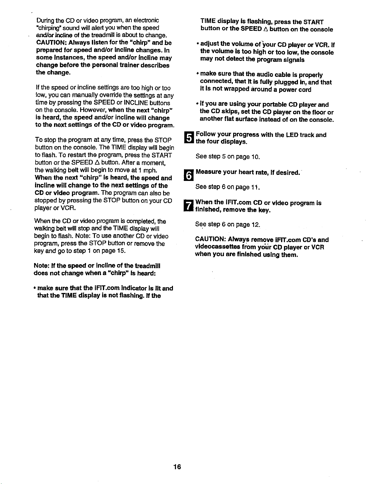
HOW TO CONNECT YOUR VCR
Note: If your VCR has an unused AUDIO OUT jack,
see Instruction A below. If the AUDIO OUT jack is
being used, see instruction B. If you have a "IV
with a built-in VCR, see instruction B. If your VCR
is connected to your home stereo, see HOW TO
CONNECT YOUR HOME STEREO on page 14.
A. Plug one end of the audio cable into the jack on the
front of the treadmill near the power cord. Plug the
other end of the cable into the included adapter.
Plug the adapter into the AUDIO OUT jack on your
VCR.
A
'."-!
iN _'_i Audio Adapter
i @--[_] 1 Cable _
B. Plug one end of the audio cable into the jack on the
front of the treadmill near the power cord. Plug the_
other end of the cable into the included adapter.
Plug the adapter into an RCA adapter (available at
electronics stores). Next, remove the wire that is
currently plugged into the AUDIO OUT jack on your
VCR and plug the wire into the unused side of the
RCA adapter. Plug the RCA adapter into the AUDIO
OUT jack on your VCR.
B
['_"_" = RCA Adapter--_
!:III_L_.0) :_ Audio . •
i@ [_] i Cable Adapte; [
/
Wire removed from.---_,-c_,J
AUDIO OUT jack
To use iFIT.com CD's or videocassettes, the treadmill
must be connected to your portable CD player, portable
stereo, home stereo, computer with CD player, or
VCR. See HOW TO CONNECT THE TREADMILL TO
YOUR CD PLAYER, VCR, OR COMPUTER on page
13. Note: To purchase iFIT.com CD's or to pur-
chase iFIT.com videocassettes, call toll-free 1-800-
735-0768.
Follow the steps below to use an iFIT.com CD or
video. Note: The instructions included in the CD
case describe how to use the CD with a variety of
PROFORM treadmills. Some instructions may not
apply to this treadmill.
D Insert the key fully into the console.
See HOW TO TURN ON THE POWER on page
10.
B
When the key is in-
serted, the manual
mode will be selected.
To use an iFIT.com CD
or video program, press
the PROGRAM button
repeatedly until the
iFIT.com indicator lights.
Press the PROGRAM button.
kl
Insert the iFIT,com CD or vldeocassette.
If you are using an iFIT.com CD, insert the CD
into your CD player. If you are using an iFIT.com
videocassette, insert the videocassette into your
VCR.
L_ Press the PLAY button on your CD player or
VCR.
A moment after the button is pressed, your personal
trainer will begin guiding you through your workout.
Simply follow your personal trainer's instructions.
Note: If the TIME display is flashing, press the
START button or the SPEED A button on the con-
sole. The treadmill will not respond to a CD or
video program when the TIME display is flashing.
15
During the CD or video program, an electronic
=chirping" sound will alert you when the speed
and/orincline of the treadmill is about to change.
CAUTION: Always listen for the "chirp" and be
prepared for speed and/or incline changes. In
some Instances, the speed and/or incline may
change before the personal trainer describes
the change.
If the speed or incline settings are too high or too
low, you can manually override the settings at any
time by pressing the SPEED or INCLINE buttons
on the console. However, when the next "chirp"
is heard, the speed and/or incline will change
to the next settings of the CD or video program.
To stop the program at any time, press the STOP
button on the console. The TIME display will begin
to flash. To restart the program, press the START
button or the SPEED Z_button. After a moment,
the walking belt will begin to move at I mph.
When the next "chirp" is heard, the speed and
incline will change to the next settings of the
CD or video program. The program can also be
stopped by pressing the STOP button on your CD
player or VCR.
When the CD or video program iscompleted, the
walking belt wilt stop and the TIME display will
begin to flash. Note: To use another CD or video
program, press the STOP button or remove the
key and go to step 1 on page 15.
Note: If the speed or incline of the treadmill
does not change when a "chirp" Is heard:
• make sure that the iFIT.com Indicator is lit and
that the TIME display is not flashing. If the
TIME display is flashing, press the START
button or the SPEED ,_button on the console
• adjust the volume of'your CD player or VCR. If
the volume Is too high or too low, the console
may not detect the program signals
• make sure that the audio cable Is properly
connected, that it is fully plugged in, and that
it is not wrapped around a power cord
• if you are using your portable CD player and
the CD skips, set the CD player on the floor or
another flat surface instead of on the console.
[]Follow your progress with the LED track and
the four displays.
See step 5 on page 10.
rd Meaaure your heart rate, If desired.
See step 6 on page 11.
_lWhen the iFiT.com CD or video program is
finished, remove the key.
See step 6 on page 12.
CAUTION: Always remove IFIT.com CD's and
videocasaettes from yot_r CD player or VCR
when you are finished using them.
16
:i:'_i_z_i_:__ ¸ %.__ , _'_._ _
:i_i_:_r":"%:"__ _ r_ - _ . " _. "• • " _-_ '_i
Our new internet site at www.iFIT.cem allows you to
access a large selection of programs that interactively
control your treadmill to help you achieve your specific
exercise goals, in addition, you can play iFIT.com
audio and video programs directly from the internet. By
adding an optional upgrade module to the console, you
can use virtually endless features on our intemet site.
Explore www.iFIT.com for details. To purchase an up-
grade module, call toll-free 1-800-735-0768.
To use programs from our intemet site, the treadmill
must be connected to your home computer. See HOW
TO CONNECT YOUR COMPUTER on page 14. In ad-
dition, you must have at least a 56K modem and an
account with an internet service provider. A list of addi-
tional system and software requirements will be found
on our internet site.
Return to the treadmill and stand on the foot
rails. Find the clip attached to the key and slide
the key onto the waistband of your clothing.
When the on-screen countdown ends, the program
will begin and the walking belt will begin to move.
Hold the handrails, step onto the walking belt, and
begin walking.
During the program, an electronic "chirping" sound
will alert you when the speed and/or incline of the
treadmill is about to change. CAUTION: Always
listen for the "chirp" and be prepared for speed
and/or incline changes.
If the speed or incline settings are too high or too
low, you can manually override the settings at any
time by pressing the SPEED or INCLINE buttons
on the console. However, when the next "chirp"
is heard, the speed and/or incline will change
to the next settings of the program.
Follow the steps below to use a program from our
internet site.
_1 Insert the key fully into the console.
See HOW TO TURN ON THE POWER on page 10.
B Press the PROGRAM button.
When the key is in-
serted, the manual
mode will be selected.
To use an iFIT.com CD
or video program, press
the PROGRAM button
repeatedly until the
iFIT.com indicator lights.
_lGo to your computer and start an intemet
connection.
B Start your web browser, if necessary, and go to
our internet site at www.iFIT.c0m.
H FoUow the desired links on our intemet site to
select a program.
Read and follow the on-line instructions for using a
program.
To stop the program at any time, press the STOP
button on the console. The TIME display will begin
to flash. To restart the program, press the START
button or the SPEED/k button. After a moment,
the walking belt will begin to move at 1 mph.
When the next "chirp" is heard, the speed and
incline will change to the next settings of the
program.
When the program is completed, the walking belt
will stop and the TIME display will begin to flash.
Note: To use another program, press the STOP
button and go to step 5 on this page.
Note: If the speed or incline of the treadmill
does not change when a "chirp" is heard, make
sure that the iFIT.com indicator is lit and that
the TIME display is not flashing. In addition,
make sure that the audio cable is properly con-
nected, that it is fully plugged in, and that it is
not wrapped around a power cord.
Foilo_ your progress with the LED track and
the four displays, ....
See step 5 on page 10.
_] Measure your heart rate, if desired.
See step 6 on page 11.
r_ Follow the on-line instructions to start the
program.
_1'i] When the program is finished, remove the
key.
When you start the program, an on-screen count-
down will begin.
See step 6 on page 12.
17
The console features an information mode that keeps
track of the total number of hours that the treadmill has
been operated and the total number of miles that the
walking belt has moved. The information mode also
allows you to switch the console from miles per hour to
kilometers per hour. In addition, the information mode
allows you to turn on and turn off the demo mode.
To select the information mode, hold down the STOP
button while inserting the key into the console. When
the information mode is selected, the following informa-
tion will be shown:
The DISTANCE/LAPS
display will show the total
number of miles that the
walking belt has moved.
DISTANCE LAPS
The TIME display will show
the total number of hours the
treadmill has been used.
I ]
TIME SEGMENT TIME
I!!
"M" for metric kilometers will
appear in the SPEED/MIN- - _"
MILE display. Press the EED MINIMILE(krn)
SPEED ,5.button to change
the unit of measurement.
IMPORTANT: The CALS/
FAT CALS/PULSE display
should be blank. If a "d"ap-
pears in the display, the con-
sole Is In the "demo" mode.
This mode Is intended to be
CALS. FAT CALS.
used only when a treadmill is displayed in a store.
When the console is In the demo mcde, the power cord
can be plugged in, the key can be removed from the
console, and the displays and indicators on the Console
will automatically light in a preset sequencel although
the buttons on the c_nsole will not operate. If a "d" ap-
pears in the CALS/FAT CALS/PULSE display when
the Information mode is selected, press the SPEED
V button so the CALS/FAT OALS/PULSE display is
blank.
To exit the information mode, remove the key from the
console.
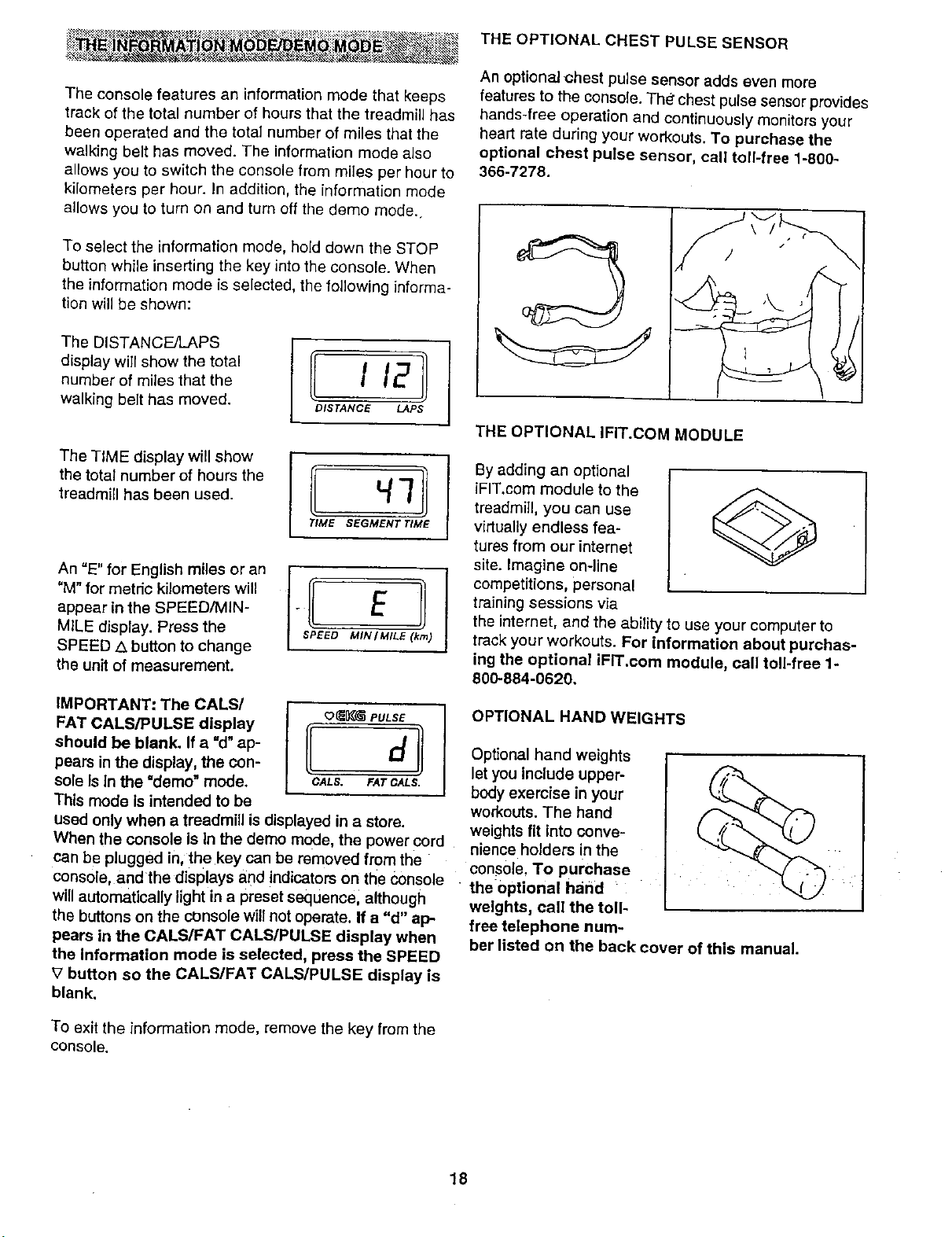
THE OPTIONAL CHEST PULSE SENSOR
An optional chest pulse sensor adds even more
features to the console. The' chest pulse sensor provides
hands-free operation and continuously monitors your
heart rate during your workouts. To purchase the
optional chest pulse sensor, call toll-free 1-800-
366-7278.
THE OPTIONAL IFIT.COM MODULE
By adding an optional
iFIT.com module to the
treadmill, you can use
virtually endless fea-
tures from our internet
site. Imagine on-line
competitions, personal
training sessions via
the internet, and the ability to use your computer to
track your workouts. For information about purchas-
ing the optional iFIT.cem module, call toll-free 1-
800-884-0620,
OPTIONAL HAND WEIGHTS
Optional hand weights
let you include upper-
body exercise in your
workouts. The hand
weights fit into conve-
nience holders in the
console. To purchase
the0ptional hand
weights, call the toll-
free telephone num-
ber listed on the back cover of this manual.
18
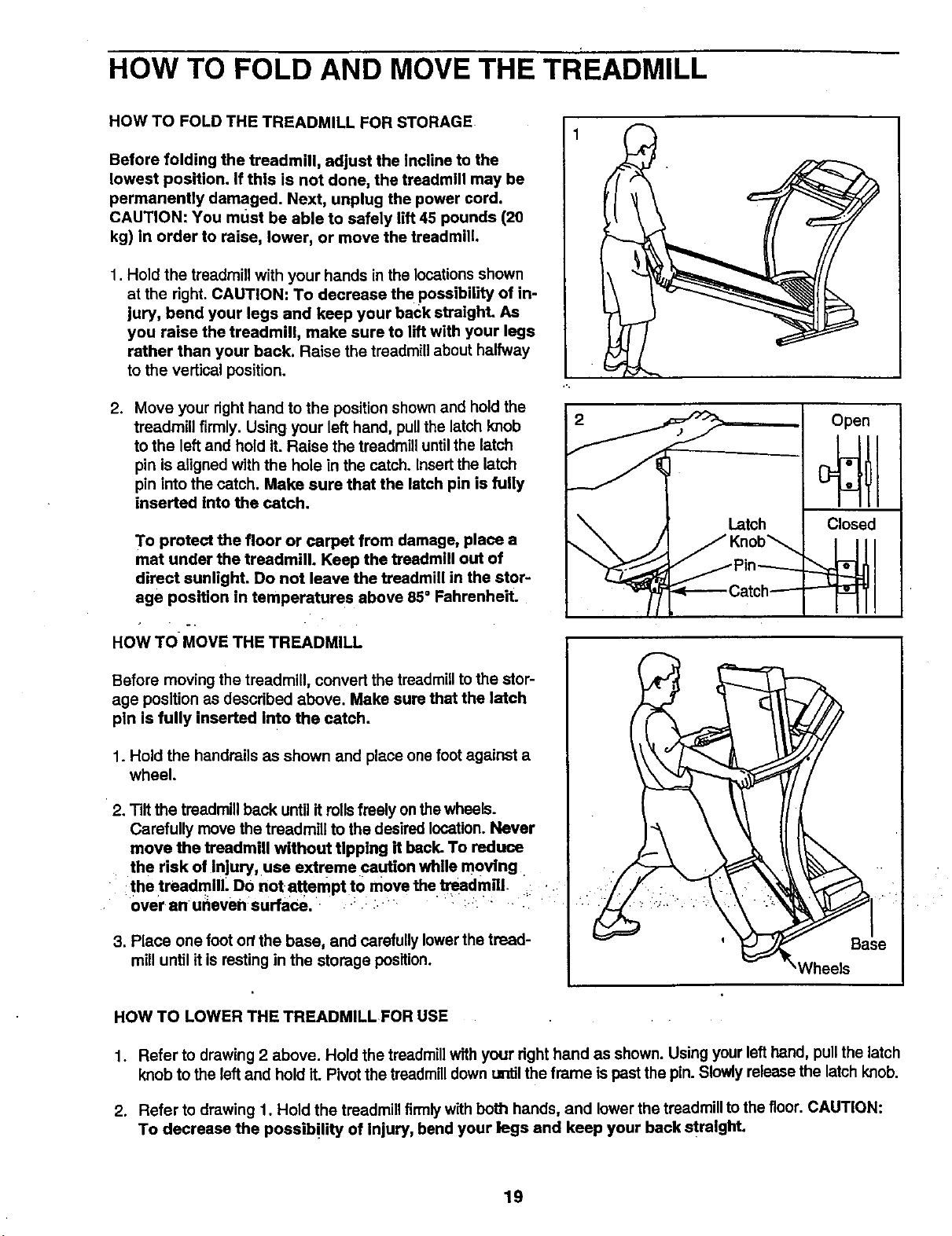
HOW TO FOLD AND MOVE THE TREADMILL
HOW TO FOLD THE TREADMILL FOR STORAGE
Before folding the treadmill, adjust the incline to the
lowest position. If this is not done, the treadmill may be
permanently damaged. Next, unplug the power cord.
CAUTION: You must be able to safely lift 45 pounds (20
kg) in order to raise, lower, or move the treadmill.
1. Hold the treadmill with your hands in the locationsshown
at the right. CAUTION: To decrease the possibility of in-
jury, bend your legs and keep your back straight. As
you raise the treadmill, make sure to lift with your legs
rather than your back. Raise the treadmill about halfway
to the vertical position.
2. Move your right hand to the position shownand hold the
treadmill firmly. Using your left hand, pull the latch knob
to the left and hold it. Raise the treadmill until the latch
pin is aligned with the hole in the catch. Insert the latch
pin into the catch. Make sure that the latch pin is fully
inserted into the catch.
To protect the floor or carpet from damage, place a
mat under the treadmill. Keep the treadmill out of
direct sunlight. Do not leave the treadmill in the stor-
age position in temperatures above 85=Fahrenheit.
HOW TO MOVE THE TREADMILL
Before moving the treadmill, convert the treadmillto the stor-
age position as dascdbed above. Make sure that the latch
pin is fully inserted into the catch.
1. Hold the handrails as shown and place one foot against a
wheel.
2. Tilt the treadmillback until it rollsfreely onthe wheals.
Carefully move the treadmill to the desired location. Never
move the treadmill without tipping it back. To reduce
the risk of Injury, use extreme caution while moving
the treadmill. DO not attempt to move the.treadmill- _i _
over anuneven surfaca. : : :
3. Place one footor/the base, and carefully lowerthe tread-
mill until it is resting in the storage position.
2
HOW TO LOWER THE TREADMILL FOR USE
1. Refer to drawing 2 above. Hold the treadmillwith your right hand as shown. Using your lefthand, pull the latch
knob to the leftand hold it. Pivot the treadmill down urdil the frame ispast the pin. Slowly release the latch knob.
2. Refer to drawing 1. Hold the treadmill firmlywith both hands, and lower the treadmill to the floor. CAUTION:
To decrease the possibility of Injury bend your legs and keep your back straight.
19
TROUBLE-SHOOTING
Most treadmill problems can be solved by following the simple steps below. Find the symptom that
applies, and follow the steps listed, if further assistance Is needed, call our toil-free HELPLINE at
1-800-736-6879, Monday through Saturday, 7 a.m. until 7 p.m. Central Time (excluding holidays).
PROBLEM: The power does not turn on
SOLUTION:
a. Make sure that the power cord is plugged into a surge suppressor, and that the surge suppressor
is plugged into a properly grounded cutlet (see page 8). Use only a single-outlet surge suppressor
that is UL 1449 listed as a transient voltage surge suppressor (TVSS). The surge suppressor
must have a UL suppressed voltage rating of 400 volts or less and a minimum surge dissipation
of 450 joules. The surge suppressor must be electrically rated for 120 volts AC and 15 amps.
Important: The treadmill is not compatible with GFCI-equipped outlets.
b. After the power cord has been plugged in, make sure that the key isfully inserted intothe console.
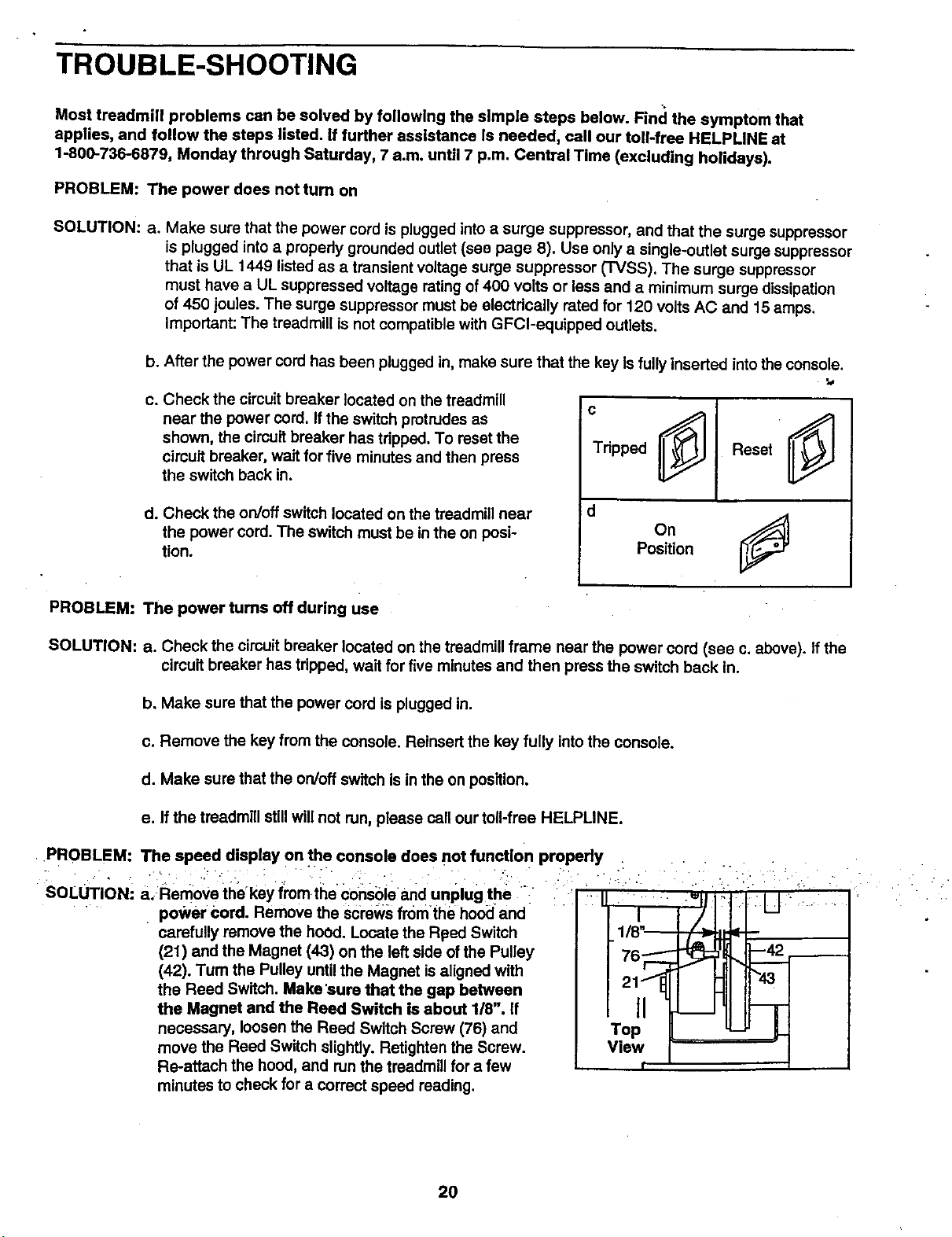
c. Check the circuit breaker located on the treadmill
near the power cord. If the switch protrudes as
shown, the circuit breaker has tripped. To reset the
cimuit breaker, wait for five minutes and then press
the switch back in.
d. Check the on/off switch located on the treadmill near
the power cord. The switch must be in the on posi-
tion.
c
Tripped ___
d
OnJ
Position
PROBLEM: The power turns off during use
SOLUTION: a. Check the circuit breaker located on the treadmill frame near the power cord (see c. above). If the
circuit breaker has tripped, wait for five minutes and then press the switch back In.
b. Make sure that the power cord is plugged in.
c. Remove the key from the console. Reinsert the key fully into the console.
d. Make sure that the on/off switch is in the on position.
e. If the treadmill stillwill not run, please call our toll-free HELPLINE.
• PROBLEM:
SoLUTIoNI a. RemoVe the'key from the consble and unplug the " i I
power Cord. Remove the Screws from the hoo_:land
carefully remove the hood. Locate the Rf_ed Switch
(21) and the Magnet (43) on the left side of the Pulley
(42). Tum the Pulley untilthe Magnet isaligned with
the Reed Switch. Make 'sure that the gap between
the Magnet and the Reed Switch is about 1/8". If
necessary, loosen the Reed Switch Screw (76) and
move the Reed Switch slightly. Retighten the Screw.
Re-attach the hood, and runthe treadmill for a few
minutes to check for a correct speed reading.
The speed display on the console does not function properly ....
" ? : : _ : . • i ." :i :
Top
View
2O
PROBLEM:Thewalkingbeltslowswhenwalkedon
SOLUTION: a. Use only a UL-listed surge suppressor, rated at 15 amps, with a 14-gauge cord of five feet or less
in length.
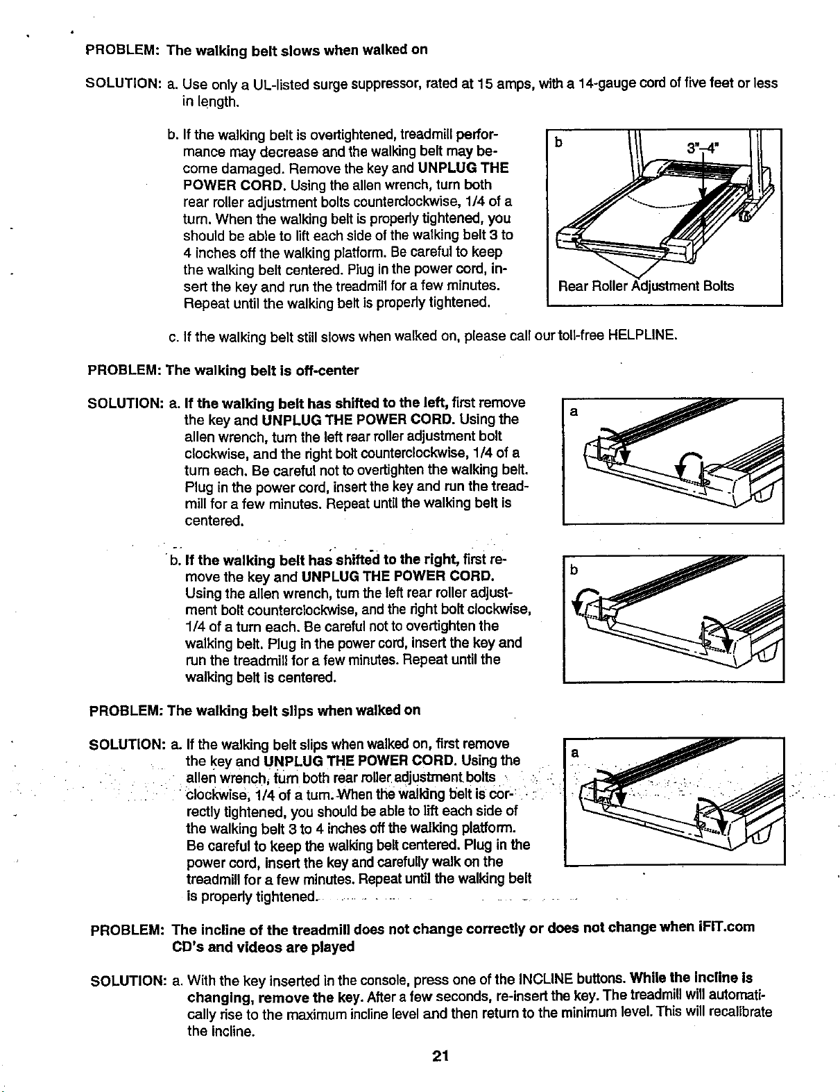
b. If the walking belt is overtightened, treadmill perfor-
mance may decrease and the walking belt may be-
come damaged. Remove the key and UNPLUG THE
POWER CORD. Using the allen wrench, turn both
rear roUeradjustment boltscounterclockwise, 1/4 of a
turn. When the walking belt is propedy tightened, you
should be able to lifteach side of the walking belt 3 to
4 inches off the walking platform. Be careful to keep
the walking belt centered. Plug in the power cord, in-
sert the key and run the treadmill for a few minutes.
Repeat until the walking belt is properly tightened.
b
Rear Roller Adjustment Bolts
c. If the walking belt still slows when walked on, please call ourtoll-free HELPUNE.
PROBLEM: The walking belt is off-center
SOLUTION: a.
If the walking belt has shifted to the left, first remove
the key and UNPLUG THE POWER CORD. Using the
allen wrench, turn the left rear rolleradjustment bolt
clockwise, and the right boltcounterclockwise, 1/4 of a
turn each. Be careful not to overtighten the walking belt.
Plug in the power cord, insertthe key and run the tread-
mill for a few minutes. Repeat untilthe walking belt is
centered.
a
bl If the walking belt has shifted to the right, first re-
move the key and UNPLUG THE POWER CORD.
Using the allen wrench, turn the left rear roller adjust-
ment bolt counterclockwise, and the right bolt clockwise,
1/4 of a turn each. Be careful notto overtighten the
walking belt. Plug in the power cord, insert the key and
run the treadmill for a few minutes. Repeat until the
walking belt is centered.
b
PROBLEM: The walking belt slips when walked on
SOLUTION: a. If the walking belt slipswhen walked on, first remove
• the key and UNPLUG THE POWER CORD. Using the a
allen wrench, turn both rear miler adjustment bolts ;
i ' ;€lockwise, 1/4 of a tum:-When the walking belt is cor-: .. :i "
recUy tightened, you should be able to lift each side of
the walking belt 3 to 4 inchesoffthe walking platform.
Be careful to keep the walking belt centered. Plug in the
power cord, insert the key and carefully walk on the
treadmill for a few minutes. Repeat until the walking belt
is properly tightened ....................
PROBLEM: The incline of the treadmill does not change correctly or does not change when iFIT.com
CD's and videos are played
SOLUTION: a. With the key inserted in the console, press one of the INCLINE buttons. While the incline is
changing, remove the key. After a few seconds, re-insert the key. The treadmillwill automati-
cally rise to the maximum inclinelevel and then return to the minimum level. This will recalibrate
the Incline.
21
CONDITIONING GUIDELINES
The following guidelines wilt help you to plan your ex-
ercise program. Remember--these are general guide-
lines only. For more detailed exercise information, ob-
tain a reputable book or consult your physician.
EXERCISE INTENSITY
Whether your goal is to bum fat or to strengthen your
cardiovascular system, the key to achieving the
desired results is to exercise with the proper intensity.
The proper intensity level can be found by using your
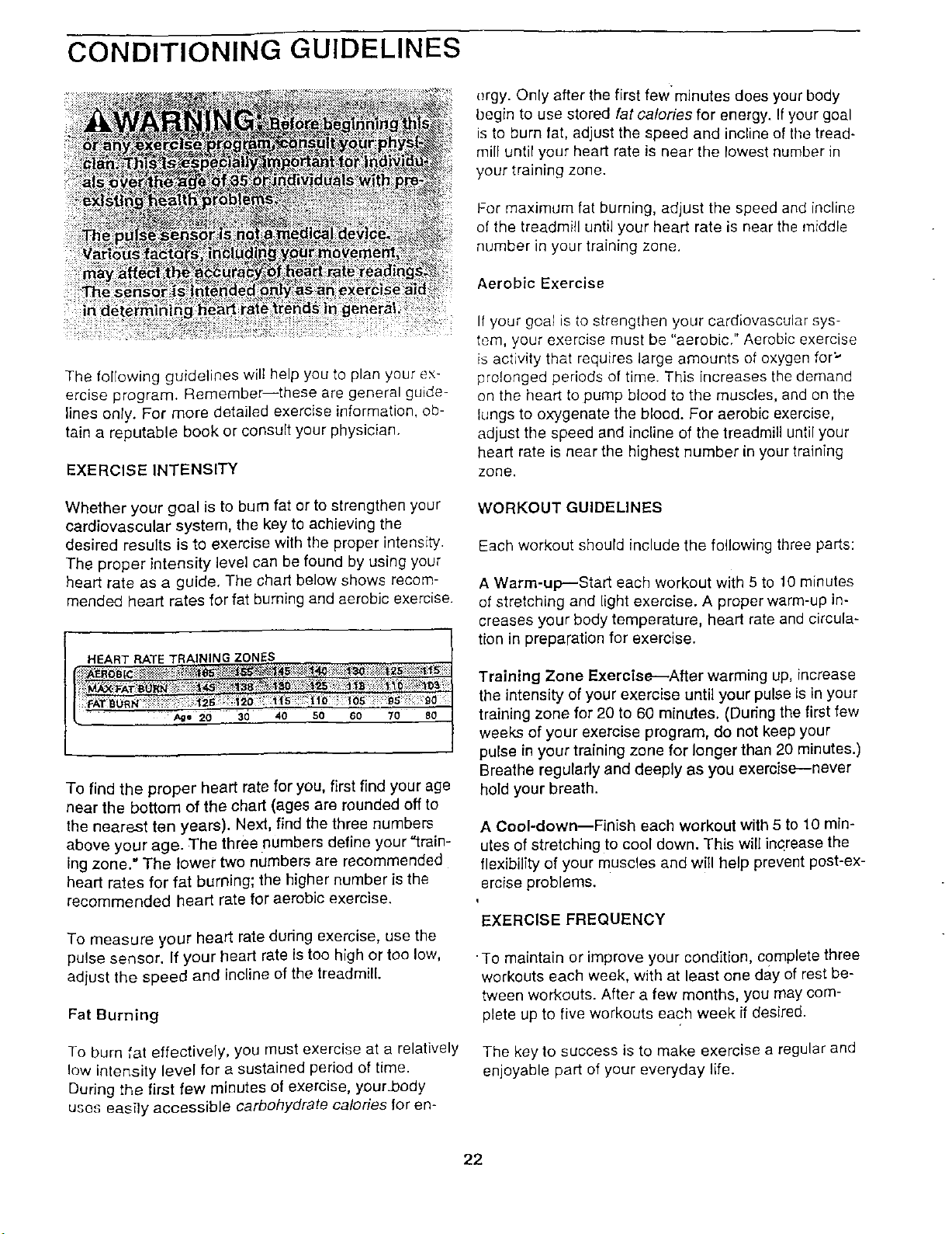
heart rate as a guide, The chart below shows recom-
mended heart rates for fat burning and aerobic exercise.
30 40 50 60 70 80
To find the proper heart rate for you, first find your age
near the bottom of the chad (ages are rounded off to
the nearest ten years). Next, find the three numbers
above your age. The three numbers define your "train-
ing zone." The lower two numbers are recommended
heart rates for fat burning; the higher number is the
recommended heart rate for aerobic exercise.
To measure your heart rate dudng exercise, use the
pulse sensor. If your heart rate is too high or too low,
adjust the speed and incline of the treadmill.
Fat Burning
To burn fat effectively, you must exercise at a relatively
low Intensity level for a sustained period of time.
During the first few minutes of exercise, your.body
uses easfty accessible carbohydrate calories for on-
orgy. Only after the first few'minutes does your body
begin to use stored fat calories for energy. If your goal
is to burn fat, adjust the speed and incline of tile tread-
mill until your heart rate is near the lowest number in
your training zone.
For maximum fat burning, adjust the speed and incline
of the treadmill until your heart rate is near the middle
number in your training zone.
Aerobic Exercise
If your goal is to strengthen your cardiovascular sys-
tem, your exercise must be "aerobic." Aerobic exercise
is activity that requires large amounts of oxygen for"
prolonged periods of time. This increases the demand
on the heart to pump blood to the muscles, and on the
lungs to oxygenate the blood. For aerobic exercise,
adjust the speed and incline of the treadmill until your
heart rate is near the highest number in your training
zone.
WORKOUT GUIDELINES
Each workout should include the following three parts:
A Warm-up--Start each workout with 5 to 10 minutes
of stretching and light exercise. A proper warm-up in-
creases your body temperature, heart rate and circula-
tion in preparation for exercise.
Training Zone Exercise--After warming up, increase
the intensity of your exercise until your pulse is in your
training zone for 20 to 60 minutes. (During the first few
weeks of your exercise program, do not keep your
pulse in your training zone for longer than 20 minutes.)
Breathe regularly and deeply as you exercise--never
hold your breath.
A Cool-down--Finish each workout with 5 to t 0 min-
utes of stretching to cool down, This will increase the
flexibility of your muscles and will help prevent post-ex-
ercise problems.
EXERCISE FREQUENCY
•To maintain or improve your condition, complete three
workouts each week, with at least one day of rest be-
tween workouts. After a few months, you may com-
plete up to _iveworkouts each week if desired.
The key to success is to make exercise a regular and
enjoyable part of your everyday life.
22
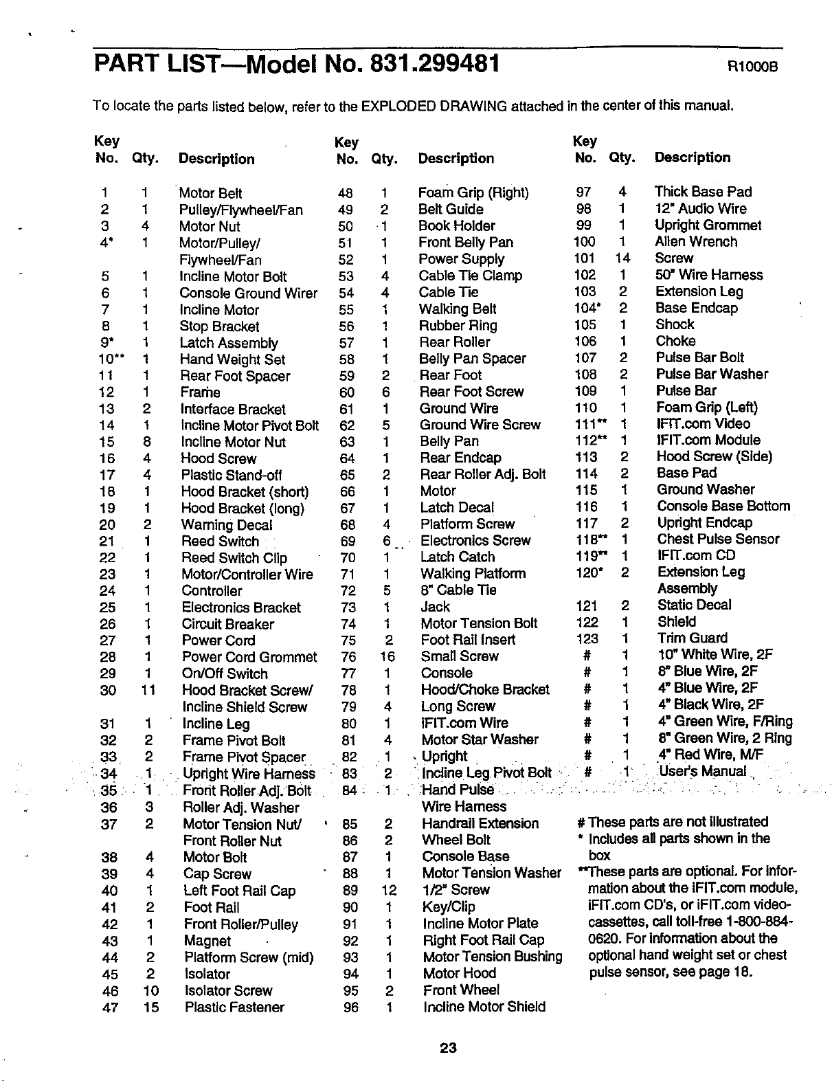
PART LIST---Model No. 831.299481 RlOOOB
To locate the parts listed below, refer to the EXPLODED DRAWING attached in the center of this manual.
Key Key Key
No, Qty. Description No. Qty. Description No. Qty. Description
1 1 Motor Belt
2 1 Pulley/Flywheel/Fan
3 4 Motor Nut
4* 1 Motor/Pulley/
Flywheel/Fan
5 1 Incline Motor Bolt
6 1 Console Ground Wirer
7 1 Incline Motor
8 1 Stop Bracket
9* 1 Latch Assembly
10"* 1 Hand Weight Set
11 1 Rear Foot Spacer
12 1 Frarhe
13 2 Interface Bracket
14 1 Incline Motor Pivot Bolt
15 8 Incline Motor Nut
16 4 Hood Screw
17 4 Plastic Stand-off
18 1 Hood Bracket (short)
19 1 Hood Bracket (long)
20 2 Waming Decal
21 1 Reed Switch
22 1 Reed Switch clip
23 1 Motor/Controller Wire
24 1 Controller
25 1 Electronics Bracket
26 1 Circuit Breaker
27 1 Power Cord
28 1 Power Cord Grommet
29 1 On/Off Switch
30 11 Hood Bracket Screw/
Incline Shield Screw
Incline Leg
Frame Pivot Bolt
Fl'ame Pivot Spacer.
Upright Wire Harness
•35. 1. Frodt RollerAdj. B01t
36 3 Roller Adj. Washer
37 2 Motor Tension Nut/
Front Roller Nut
38 4 Motor Bolt
39 4 Cap Screw
40 1 Left Foot Rail Cap
41 2 Foot Rail
42 1 Front Roller/Pulley
43 1 Magnet
44 2 Platform Screw (mid)
45 2 Isolator
46 10 Isolator Screw
47 15 Plastic Fastener
31 1
32 2
33 2
:-34 .1 .
48 1 Foam Gdp (Right) 97 4 Thick Base Pad
49 2 Belt Guide 98 1 12" Audio Wire
50 •1 Book Holder 99 1 Upright Grommet
51 1 Front Belly Pan 100 1 Allen Wrench
52 1 Power Supply 101 14 Screw
53 4 Cable Tie Clamp 102 1 50" Wire Harness
54 4 Cable Tie 103 2 Extension Leg
55 1 Walking Belt 104" 2 Base Endcap
56 1 Rubber Ring 105 1 Shock
57 1 Rear Roller 106 1 Choke
58 1 Belly Pan Spacer 107 2 Pulse Bar Bolt
59 2 Rear Foot 108 2 Pulse Bar Washer
60 6 Rear Foot Screw 109 1 Pulse Bar
61 1 Ground Wire 110 1 Foam Grip (Left)
62 5 Ground wire Screw 111"* 1 IFIT.com Video
63 1 Belly Pan 112"* 1 IFIT.com Module
64 1 Rear Endcap 113 2 Hood Screw (Side)
65 2 Rear Roller Adj. Bolt 114 2 Base Pad
66 1 Motor 115 1 Ground Washer
67 1 Latch Decal 116 1 Console Base Bottom
68 4 Platform Screw 117 2 Updght Endcap
69 6 Electronics Screw 118" 1 Chest Pulse Sensor
70 1 Latch Catch 119"* 1 IFIT.com CD
71 1 Walking Platform 120" 2 Extension Leg
72 5 8"Cable Tie Assembly
73 1 Jack 121 2 Static Decal
74 1 Motor Tension Bolt 122 1 Shield
75 2 Foot Rail Insert 123 1 Tdm Guard
76 16 Small Screw # 1 10"White Wire, 2F
77 1 Console # 1 8_Blue Wire, 2F
78 1 Hood/Choke Bracket # 1 4" Blue Wire, 2F
79 4 Long Screw # 1 4" Black Wire, 2F
80 1 IFIT.com Wire # 1 4" Green Wire, F/Ring
81 4 Motor Star Washer # 1 8"Green Wire, 2 Ring
82 1 . Updght _ # 1 4" Red Wire, M/F
83 2 i incline Leg Pivot Bolt # 1 User's Manual
84_ 1 •Hand Pulsell ..... : .._::. ............. _....... .. .........
Wire Hamess
85 2 Handrail Extension
86 2 Wheel Bolt
87 1 Console Base
88 1 Motor Tension Washer
89 12 1/2" Screw
90 1 Key/Clip
91 1 Incline Motor Plate
92 1 Right Foot Rail Cap
93 1 Motor Tension Bushing
94 1 Motor Hood
95 2 Front Wheel
96 1 Incline Motor Shield
# These parts are not illustrated
* Includesall pads shown in the
box
**These parts are optional. For infor-
mation about the iFIT.com module,
iFIT.com CD's, or iFIT.com video-
cassettes, call toll-free 1-800-884-
0620. For information about the
optional handweight set or chest
pulse sensor, see page 18.
23
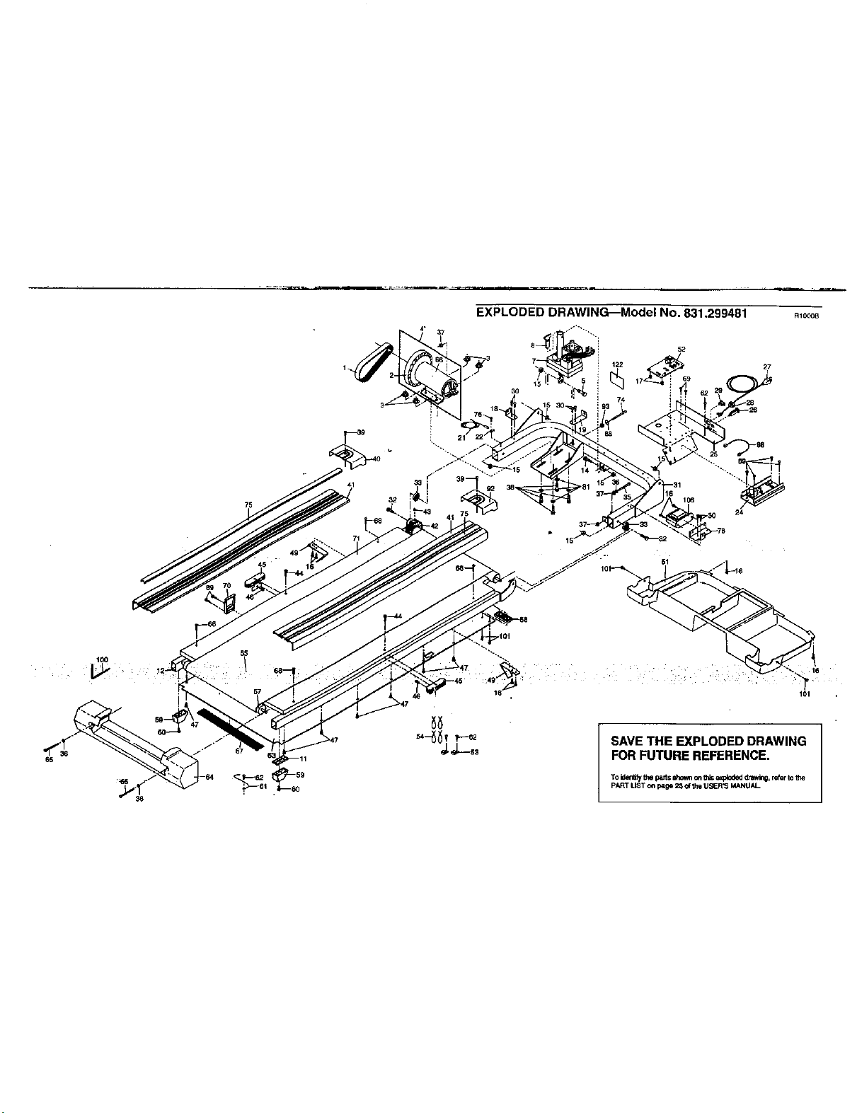
EXPLODED DRAWING--Model No. 831.299481
RIOOOB
"1"0 51 . /"*
101
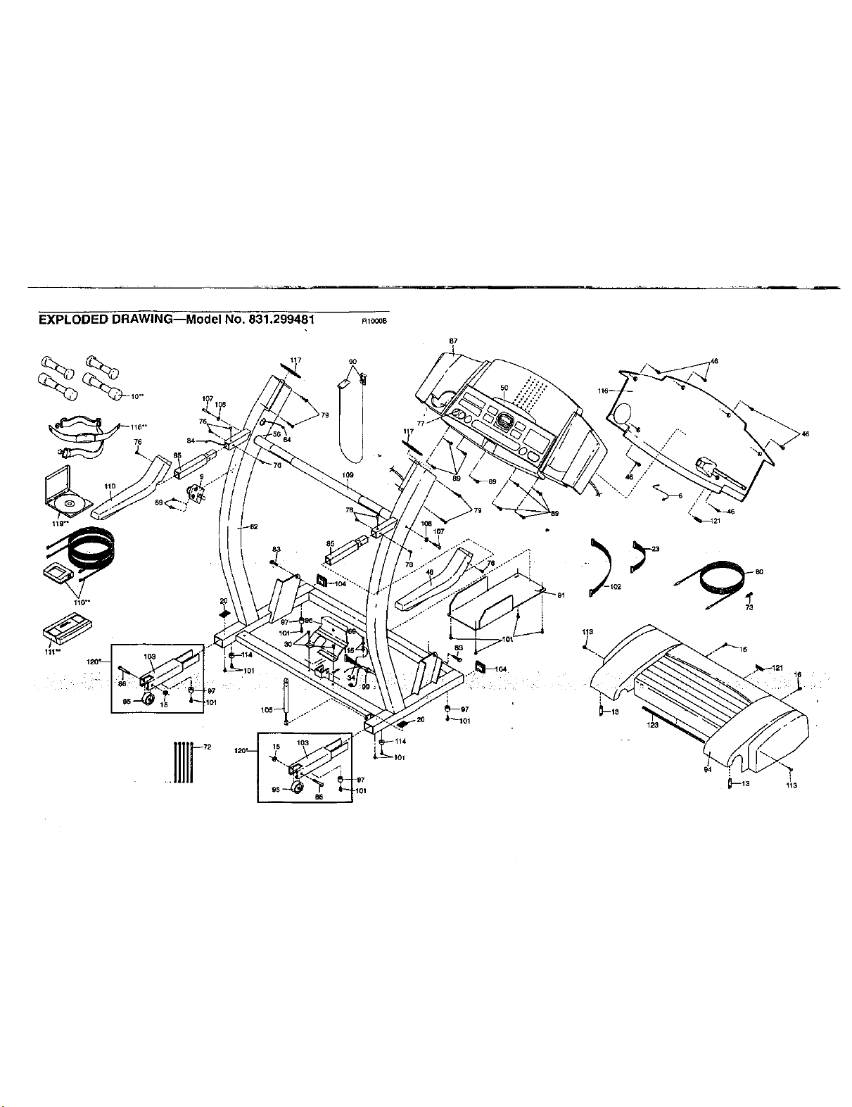
EXPLODED DRAWING--Model No. 831.299481
118"
RIOOOB
109
85
87
117
113
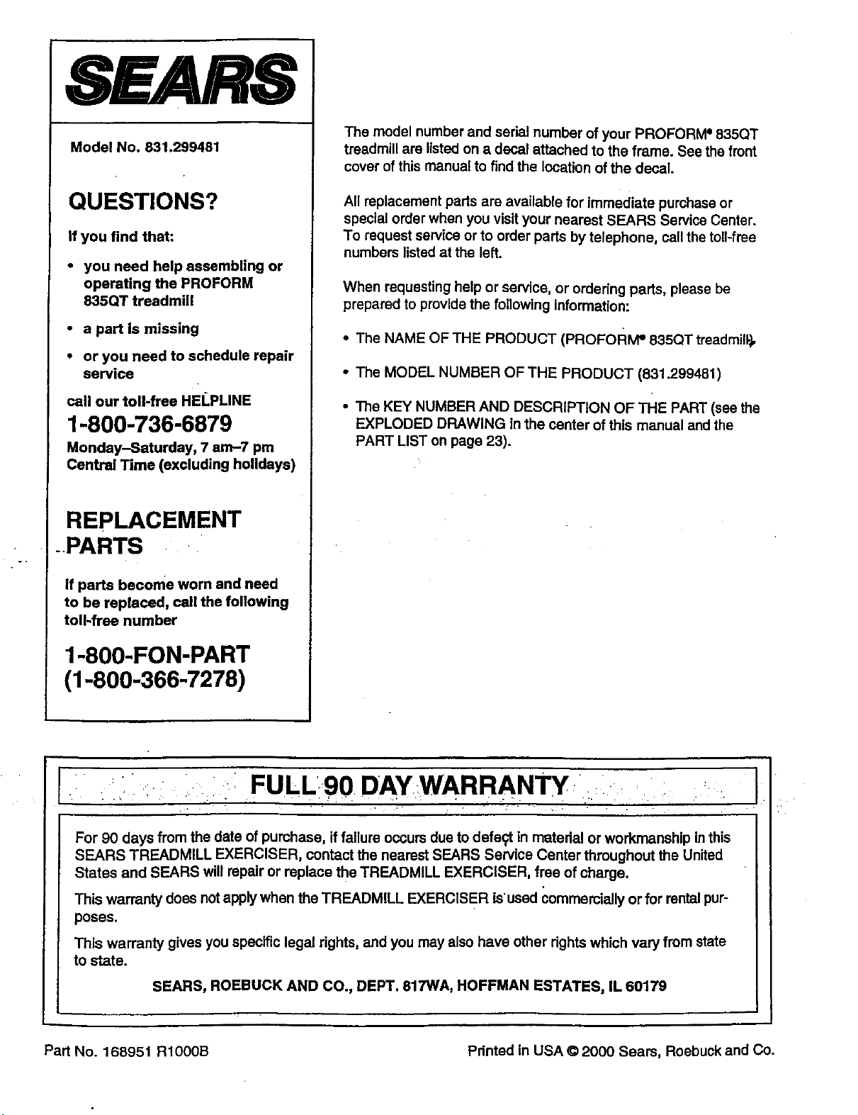
8EARS
Model No, 831.299481
QUESTIONS?
If you find that:
• you need help assembling or
operating the PROFORM
835QT treadmill
• a part is missing
• or you need to schedule repair
service
call our toll-free HEI.PLINE
1-800-736-6879
Monday-Saturday, 7 am-7 pm
Central Time (excluding holidays)
REPLACEMENT
.PARTS
If parts become worn and need
to be replaced, call the following
toll-free number
1-800-FON-PART
(1-800-366-7278)
The model number and serial number of your PROFORM =835QT
treadmill are listed on a decal attached to the frame. See the front
cover of this manual to find the location of the decal.
All replacement parts are available for immediate purchase or
special order when you visit your nearest SEARS Service Center.
To request service or to order parts by telephone, call the toll-free
numbers listedat the left.
When requesting help or service, or ordering parts, please be
prepared to provide the following Information:
• The NAME OF THE PRODUCT (PRoFoRIvP 835QT treadmill.),,
• The MODEL NUMBER OFTHE PRODUCT (831.299481)
• The KEY NUMBER AND DESCRIPTION OF THE PART (see the
EXPLODED DRAWING in the center of this manual and the
PART LIST on page 23).
If : ii : i: FULLgO DAYWARRANTY
For 90 days from the date of purchase, if failure occurs due to defegt in matedal or workmanship in this
SEARS TREADMILL EXERCISER, contact the nearest SEARS Service Center throughout the United
States and SEARS will repair or replace the TREADMILL EXERCISER, free of charge.
This warranty does not apply when the TREADMILL EXERCISER is'used commercially or for rental pur-
poses.
This warranty gives you specific legal dghts, and you may also have other rights which vary from state
to state.
SEARS, ROEBUCK AND CO., DEPT. 817WA, HOFFMAN ESTATES, IL 60179
Part No. 168951 RIOOOB Pdntod in USA © 2000 Sears, Roebuck and Co.