Loading ...
Loading ...
Loading ...
17
• Before switching it on, test the supply terminal tier (L, N terminals) and grounding points with 500V megaohm meter and
check if the resistance is above 1MΩ. It can't be operated if it is below 1MΩ.
• Connect it to the power supply of outdoor units to energize the heating belt of the compressor. To protect the
compressor at startup, power it on 12 hours prior to the operation.
Check if the arrangements of the drainpipe and connection line are correct.
The drainpipe shall be placed at the lower part while the connection line placed at the upper part. Heat preservation
measures should be taken such as winding the drainpipe esp. in the indoor units with heating insulating materials.
The drain pipe should be made a slope type to avoid protruding at the upper part and concaving at the lower part on the
way.
Checkup of Installation
Check if the mains voltage is matching
Check if there is air leakage at the piping joints
Check if the connections of mains power and indoor & outdoor units are correct
Check if the serial numbers of terminals are matching
Check if the installation place meets the requirement
Check if there is too much noise
Check if the connecting line is fastened
Check if the connectors for tubing are heat insulated
Check if the water is drained to the outside
Check if the indoor units are positioned
Test Run & Failure Code
Before Test Run
Do ask the installation personnel to make a test run. Take the testing procedures according to the manual and check if the
temperature regulator works properly.
When the machine fails to start due to the room temperature, the following procedures can be taken to do the compulsive
running. The function is not provided for the type with remote control.
• Set the wired controller to refrigerating/heating mode, press "ON/OFF" button for 5 seconds to enter into the compulsive
refrigerating/heating mode. Repress "ON/OFF" button to quit the compulsive running and stop the operation of the air
conditioner.
Ways of Test Run
Fault Remedies
When any fault appears, refer to “Inquiry of fault records of indoor units" at the previous page, consult the fault code of
line control or the ashing times for LED5 of computer panel of indoor units/health lamp of receiving window of remote
control and nd out the faults as shown in the following table to remove all faults.
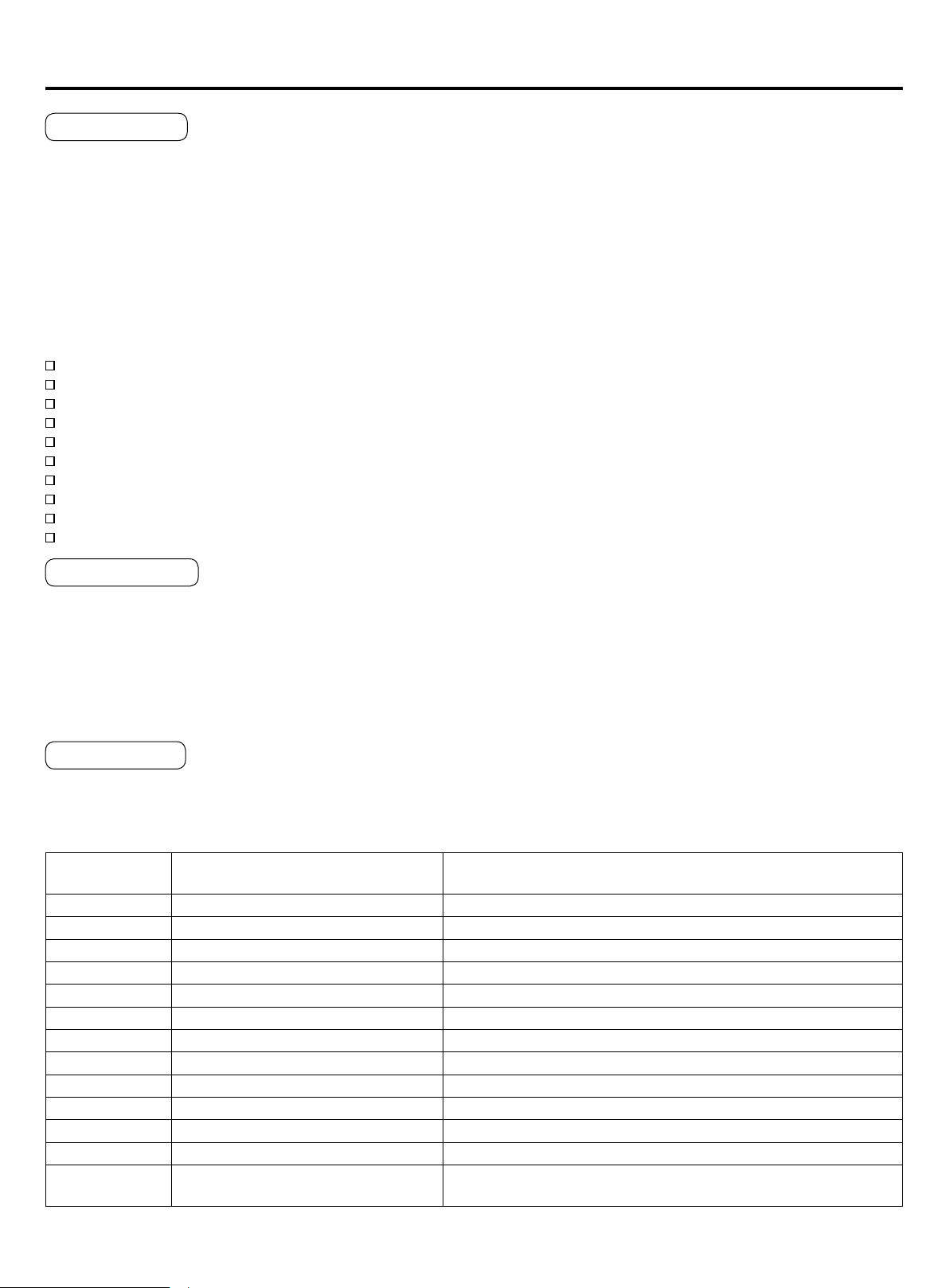
Indoor Unit Faults
Failure code at
wired controller
PCB LED5(Indoor Units) / Receiver
Timer Lamp(Remote Controller)
Fault Descriptions
01 1 Fault of indoor unit ambient temp. transducer TA
02 2 Fault of indoor unit pipe temp. transducer TC1
03 3 Fault of indoor unit pipe temp. transducer TC2
04 4 Fault of indoor unit dual heat source temp. transducer
05 5 Fault of indoor unit EEPROM
06 6 Fault of communication between indoor & outdoor units
07 7 Fault of communication between indoor unit and wired control
08 8 Fault of indoor unit water drainage
09 9 Fault of duplicate indoor unit address
0A 10 Fault of duplicate central control address
0C 12 Fault of zero crossing
0E 14 Fault of DC fan
Outdoor Unit
Code
20 Corresponding faults of outdoor units
Loading ...